General Safety

SAFETY FIRST!
We care about YOU. Please, always wear your safety glasses and protective gloves when servicing RockShox products.
Protect yourself! Wear your safety gear!







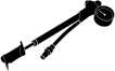
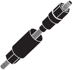


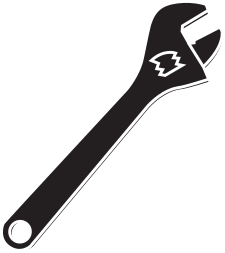





SAFETY FIRST!
We care about YOU. Please, always wear your safety glasses and protective gloves when servicing RockShox products.
Protect yourself! Wear your safety gear!
Torque: Parts must be tightened to the specified torque. Failure to do so can result in SERIOUS INJURY OR DEATH.
Installation: SRAM recommends that you have your RockShox suspension installed by a qualified bicycle mechanic. Installation requires knowledge of bicycle and suspension components, as well as the use of specialized tools. Incorrect installation can lead to SERIOUS INJURY OR DEATH.
Cables/Housing/Brake Hose: Do not allow cables, housing, or brake hose to rest on or be attached to the fork crown, steerer tube, or upper tubes. Contact and abrasion over time could result in damage to components, loss of control, and possible SERIOUS INJURY OR DEATH. Damage from abrasion is not covered under warranty.
Brake Hose/Housing: Secure the brake hose or housing in the fork cable guide, or to the fork lower leg with a cable tie. Failure to secure the brake hose or housing could affect braking which could result in SERIOUS INJURY OR DEATH. Compress the fork to full bottom out and confirm the hose or housing does not contact the tire. Contact can damage the brake hose or housing and could affect braking which could result in SERIOUS INJURY OR DEATH.
Internal Routing: Confirm internally routed cables, housing or brake hoses do not contact the steerer tube. Any contact may cause abrasions, which over time can cause damage which may result in loss of control, leading to SERIOUS INJURY OR DEATH. Inspect the steerer tube during service intervals to ensure the steerer tube is not worn or damaged. If damaged, replace the crown steerer upper tube prior to riding to avoid SERIOUS INJURY OR DEATH. If resistance is felt while steering, stop riding and confirm the cables, housing, and brake hoses are not making contact with the steerer tube. Eliminate contact prior to riding to avoid SERIOUS INJURY OR DEATH.
Tire Clearance: Tire: Failure to leave at least 6 mm clearance between the top of the inflated tire and the bottom of the crown will cause the tire to jam against the crown when the fork is fully compressed, which can result in SERIOUS INJURY OR DEATH. Fender: Failure to leave at least 6 mm clearance from the fender stay and the tire sidewall, and 6 mm between the fender stay and the disc brake caliper, can result in SERIOUS INJURY OR DEATH.
Fork Crown/Steerer/Upper Tube: Single Crown Forks: Do not attempt to separate the fork steerer tube or upper tubes from the crown. Separation, or partial separation, will cause chassis failure, SERIOUS INJURY OR DEATH. Dual Crown Forks: Do not attempt to separate the fork steerer tube from the lower crown. Separation, or partial separation, will cause chassis failure, SERIOUS INJURY OR DEATH.
Fork Steerer Tube: To avoid steerer tube failure, which can lead to SERIOUS INJURY OR DEATH, do not cut threads into a non-threaded steerer tube.
Anti-Lock Brake System (ABS): To avoid ABS malfunction, install all ABS components according to the manufacturer's instructions. Secure the ABS component wires to the fork lower leg as instructed by the manufacturer. Failure to secure wires could affect function and braking which could result in SERIOUS INJURY OR DEATH. Compress the fork to full bottom out and confirm the wires do not contact the tire, the disc brake caliper, or the disc brake rotor. Contact can damage the wire which can affect function and braking, and could result in SERIOUS INJURY OR DEATH.
Cleaning: Do not use vinegar of any type to clean any part of a RockShox suspension product. Vinegar can cause permanent damage to parts which can, over time, result in product structural failure, serious injury, and possibly death.
1. Follow the safety instructions listed here. Any failure to follow these safety instructions could cause you to crash while riding your bicycle, which could result in serious and/or fatal injuries.
2. Have a qualified bicycle mechanic install your RockShox suspension fork (fork) and/or rear shock (shock). It is extremely important that the fork or shock is installed correctly. Improperly installed forks or shocks are extremely dangerous.
3. Except as expressly instructed in the RockShox user manual and/or service manual, do not modify your fork. Modifications may cause the fork to malfunction, and make your bicycle unsafe to ride. Modification will also void your warranty.
4. The fork on your bicycle is designed for use by a single rider. Off-road forks can be used on mountain trails and similar off-road conditions. Urban forks should only be used on pavement and/or unimproved roads and dirt paths. Urban forks should not be used on mountain trails or similar off-road conditions.
5. Before riding your bicycle, confirm the brakes are properly installed and adjusted. Use the brakes carefully and learn the brakes’ characteristics by first practicing your braking technique in non-emergency situations. Hard braking, improper use of the front brake, or brakes that are out of adjustment, improperly installed, or are not used properly, can cause you to crash, and sustain serious and/or fatal injuries.
6. Before riding your bicycle confirm you are using the correctly sized wheels for your fork and bicycle. Confirm the wheels are properly installed and secured to the bicycle, and are used with compatible components. Your RockShox fork is designed to secure a front wheel using a quick release axle or thru axle. Be sure you understand which axle your bike has and how to properly operate it. Do not use a bolt on axle with your fork.
7. Riding a bicycle with the incorrect wheel size, improperly installed wheels, or incompatible components may allow the wheels to disengage from the bicycle, which can cause you to crash, and sustain serious and/or fatal injuries.
8. Check the tire clearance to the fork whenever you change tires. Failure to leave at least 6 mm of clearance between the top of the inflated tire and the bottom of the fork crown will cause the tire to jam against the crown when the fork is fully compressed. This can lead to a crash and serious injury and/or death to the rider. To check tire clearance, compress the fork completely to ensure there is at least 6 mm of clearance between the top of the inflated tire and the bottom of the crown.
9. Do not allow cables, housing, or brake hose to rest on or be attached to the fork crown, steerer tube, or upper tubes. Confirm internally routed cables, housing, or brake hoses DO NOT contact the steerer tube. Contact and abrasion over time could result in damage to components, loss of control, and possible INJURY OR DEATH. Damage from abrasion is not covered under warranty.
10. Your fork or shock may fail in certain circumstances, including, but not limited to, conditions that cause a loss of oil and/or air; collisions or other activity that bends or breaks any part of the fork or shock. Extended periods of non-use may also cause your fork or shock to fail. Do not ride your bicycle if you notice: loss of oil and/or air; sounds of excessive topping out; bent or broken fork or shock parts; or any other indications of a possible fork or shock failure, such as loss of shock absorbing properties. Fork and shock failure may not be visible. If you suspect your fork or shock may be damaged, stop riding and take your bike to a qualified dealer for inspection and repair.
11. Always use genuine RockShox replacement parts. Use of aftermarket replacement parts other than RockShox parts voids the warranty on your fork or shock and could cause structural failure to the fork or shock. Structural failure of the fork or shock can cause you to crash, and sustain serious and/or fatal injuries.
12. Do not tilt the bicycle to either side when mounting the bicycle to a carrier by the fork drop-outs (i.e., when the front wheel is removed). The fork legs may suffer structural damage if the bicycle is tilted while the drop-outs are in the carrier. Make sure the fork is securely fastened according to the bike carrier’s instructions. Make sure the rear wheel is securely fastened when using any bike carrier that secures the fork’s drop-outs. Not securing the rear wheel can allow the bicycle’s mass to side load the drop-outs, causing the drop-out to break or crack. If the bicycle tilts or falls out of its carrier, do not ride the bicycle until the fork is properly examined for possible damage; take your bicycle to a qualified dealer for inspection and repair. A fork leg or drop-out failure can cause you to crash, and sustain serious and/or fatal injuries. To locate a dealer near you, consult the International Distributor List available on-line at www.sram.com.
13. For forks designed for use with rim type brakes, install rim type brakes to the existing brake posts only. Do not use any brake other than those intended by the brake manufacturer to work with a hangerless brace. Do not route the front brake cable and/or cable housing through the stem or any other mounts or cable stops.
14. For forks designed for use with disc-style brakes, follow the brake manufacturer’s instructions for proper installation of the brake caliper. For forks using a post style disc brake mount, ensure that your brake caliper mounting bolts have between 9 and 12 mm of thread engagement and are tightened to 9-10 N•m (80-90 in-lb) when installed on the fork. Failure to have proper thread engagement can damage the brake mounting posts, which can cause you to crash, and sustain serious and/or fatal injuries.
15. Follow the user manual or service manual instructions for maintenance and service of your fork or shock.
16. RockShox forks do not come with the reflectors required by federal law for new bicycles, 16 cfr §1512.16. Additional requirements for reflectors and lighting may exist and vary by location. Your dealer should install proper reflectors and lighting systems to meet all applicable federal, state, and local requirements. Always use front and rear lights in addition to reflectors if riding at night or in reduced visibility.
17. If your shock will not return to full extension, do not attempt to service or disassemble your shock. Attempting to service a shock that will not return to full extension can cause severe and/or fatal injuries.
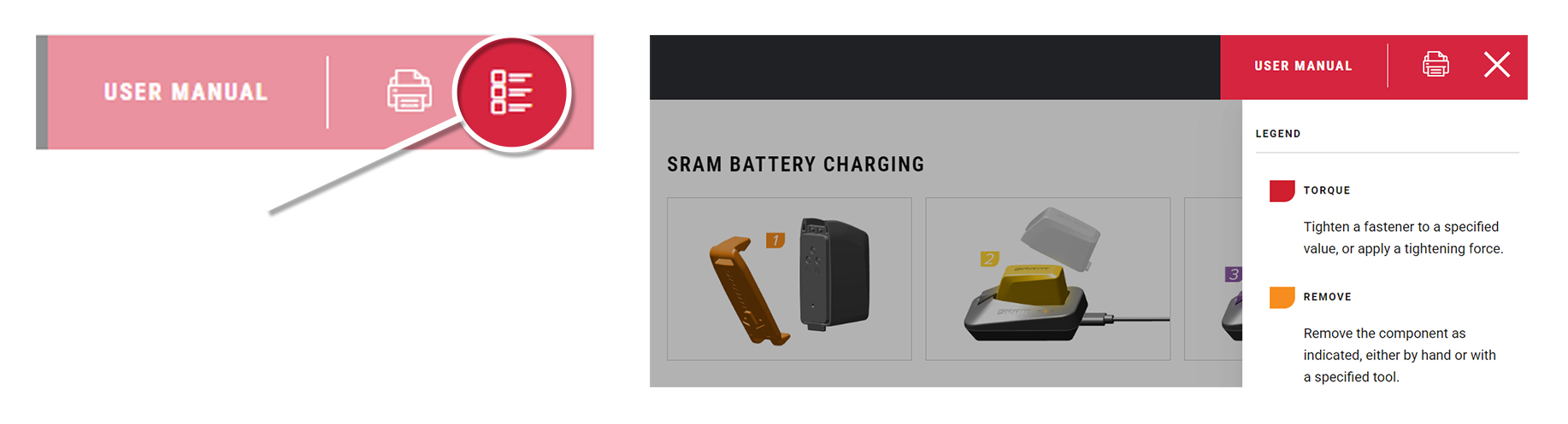
Click on the icon at the top right corner of the screen to display the color legend and the complete list of tools and supplies for this manual in a scrollable dropdown list.
The colors and symbols featured in this manual correspond to specific actions or procedures. A detailed description for each color and symbol is contained in the dropdown.
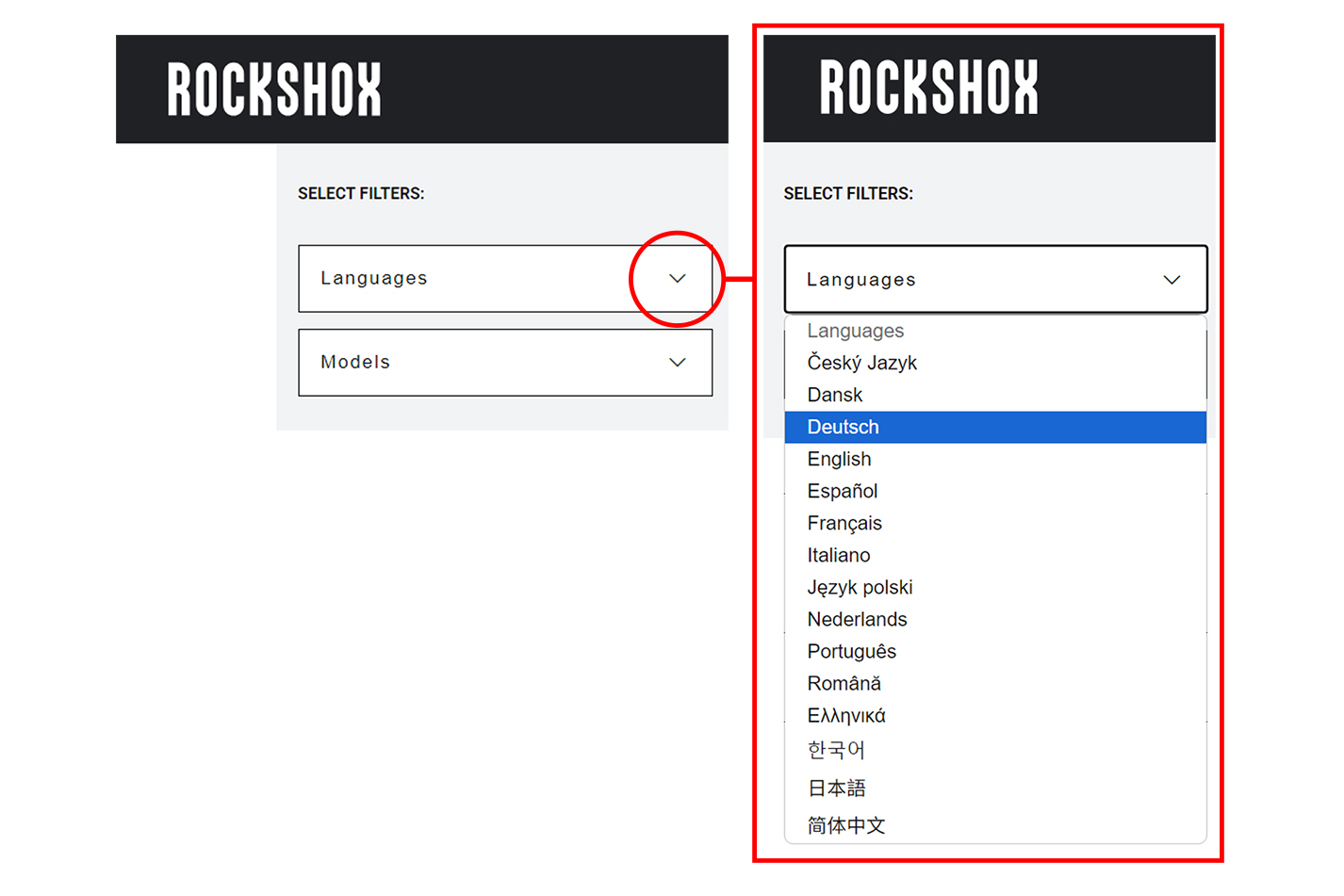
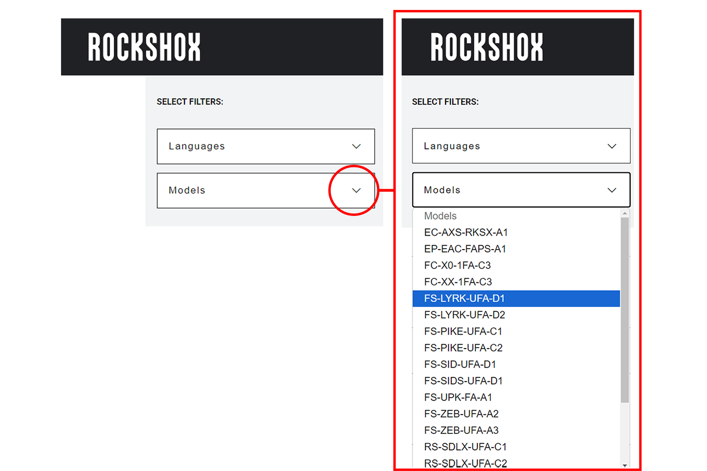
Use the dropdown lists in the SELECT FILTERS: window at the top left of the page to select the preferred language, product model code, and instructional content. Product instructional content filters will vary.
Language Filter: Select Language first. When a new language is selected, all other selected filters will reset.
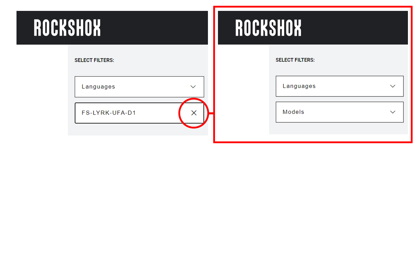
All non-Language Filters: To reset a non-language filter, click on the X.
Product model code and specification details can be identified with the serial number on the product. Model codes can be used to identify the product type, series name, model name, and product version associated with the production model year. Product details can be used to identify spare parts, service kit, and lubricant compatibility.
Model Code example: FS-LYRK-UFA-D1
FS = Product Type - Front Suspension
LYRK = Platform/Series - Lyrik
UFA = Model - Ultimate Flight Attendant
D1 = Version - (D - fourth generation, 1 - first iteration)
To identify the model code, locate the serial number on the product and enter it into the Search by Model Name or Serial Number field at www.sram.com/service.
Your product's appearance may vary from those pictured in this manual.
Images and examples pictured are for conceptual purposes and may vary from product design, appearance, and performance.
Consult sram.com/service whenever a separate manual is referenced in this document.
Read the full warranty policy for your components at sram.com/en/service/warranty.
For information about trademarks used in this manual, visit sram.com/website-terms-of-use.
Highly specialized tools and supplies are required for the replacement and maintenance of your SRAM components. We recommend that you have a qualified SRAM dealer work on your SRAM components.
CRASH HAZARD
Torque: Parts must be tightened to the specified torque. Failure to do so can result in SERIOUS INJURY OR DEATH.
Installation: SRAM recommends that you have your RockShox suspension installed by a qualified bicycle mechanic. Installation requires knowledge of bicycle and suspension components, as well as the use of specialized tools. Incorrect installation can lead to SERIOUS INJURY OR DEATH.
Internal Routing: Confirm internally routed cables, housing or brake hoses do not contact the steerer tube. Any contact may cause abrasions, which over time can cause damage which may result in loss of control, leading to SERIOUS INJURY OR DEATH. Inspect the steerer tube during service intervals to ensure the steerer tube is not worn or damaged. If damaged, replace the crown steerer upper tube prior to riding to avoid SERIOUS INJURY OR DEATH. If resistance is felt while steering, stop riding and confirm the cables, housing, and brake hoses are not making contact with the steerer tube. Eliminate contact prior to riding to avoid SERIOUS INJURY OR DEATH.
Fork Steerer Tube: To avoid steerer tube failure, which can lead to SERIOUS INJURY OR DEATH, do not cut threads into a non-threaded steerer tube.
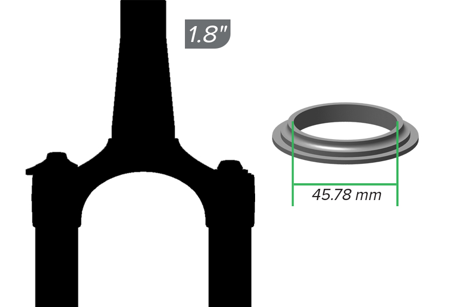
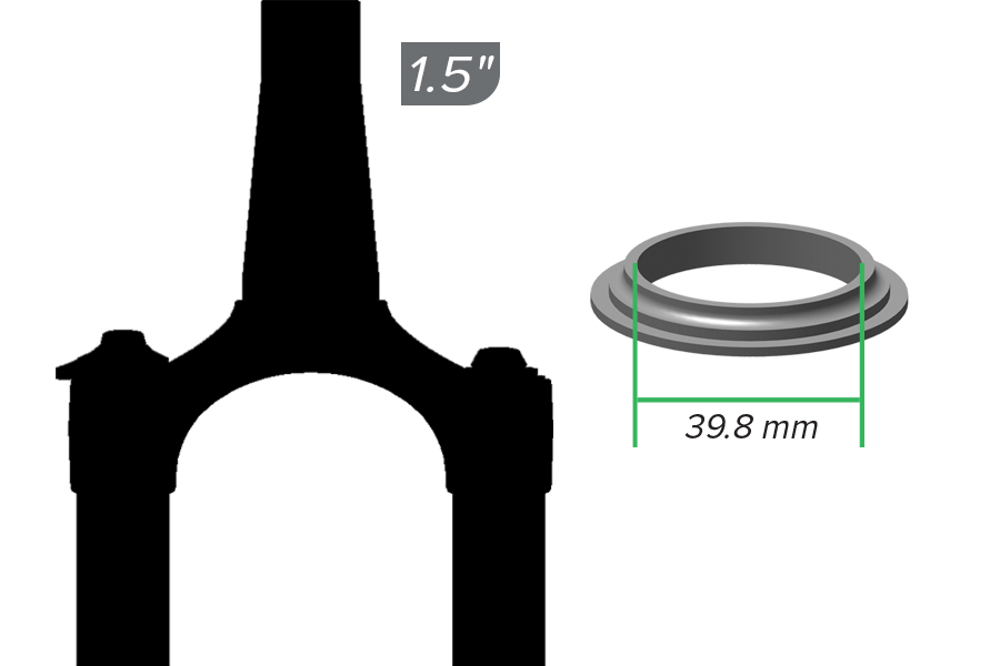
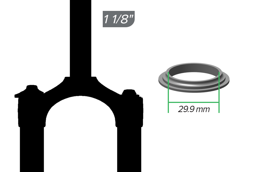
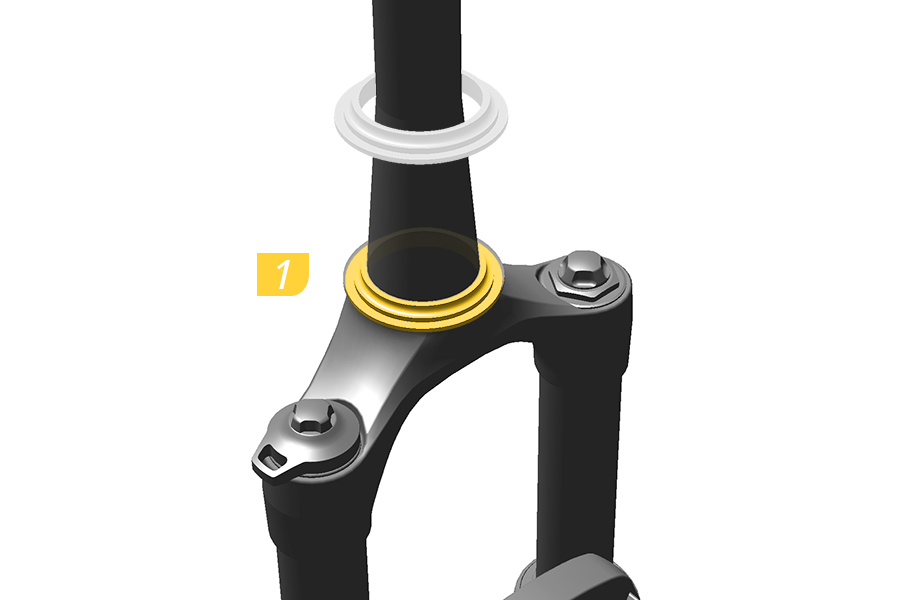
1. Install a headset into the bicycle frame and a crown race onto the fork according to your headset manufacturer’s instructions.
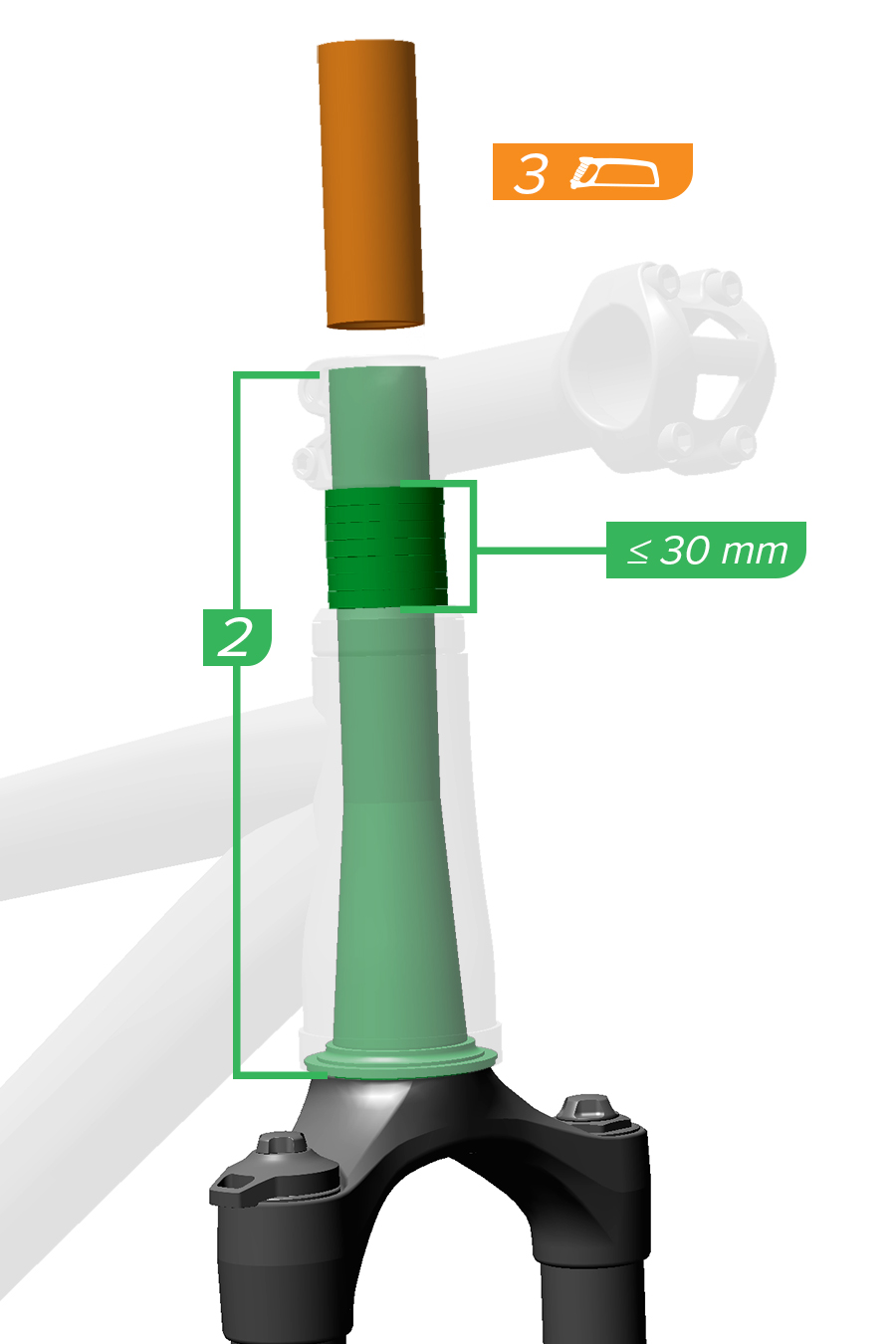
2-3. Measure and cut the steerer tube according to the stem manufacturer’s instructions. Be sure to account for the stack height of added spacers prior to cutting.
Smooth the cut area with 400 grit sandpaper or a file.
No more than 30 mm of spacers should be installed below the stem.
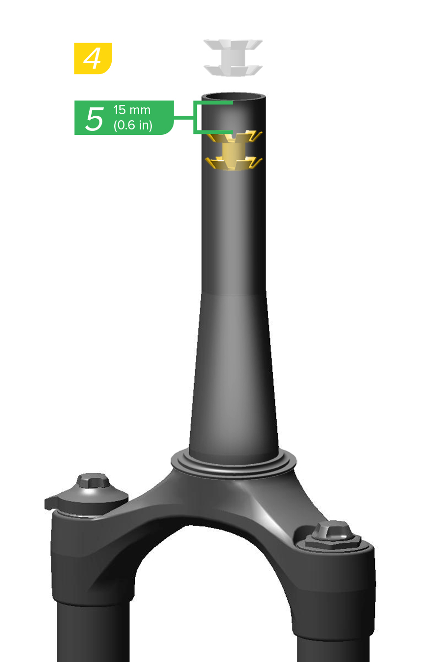
4-5. Use a star nut setter to install a star nut 15 mm (0.6 inches) into the steerer tube. Install the fork into the frame.
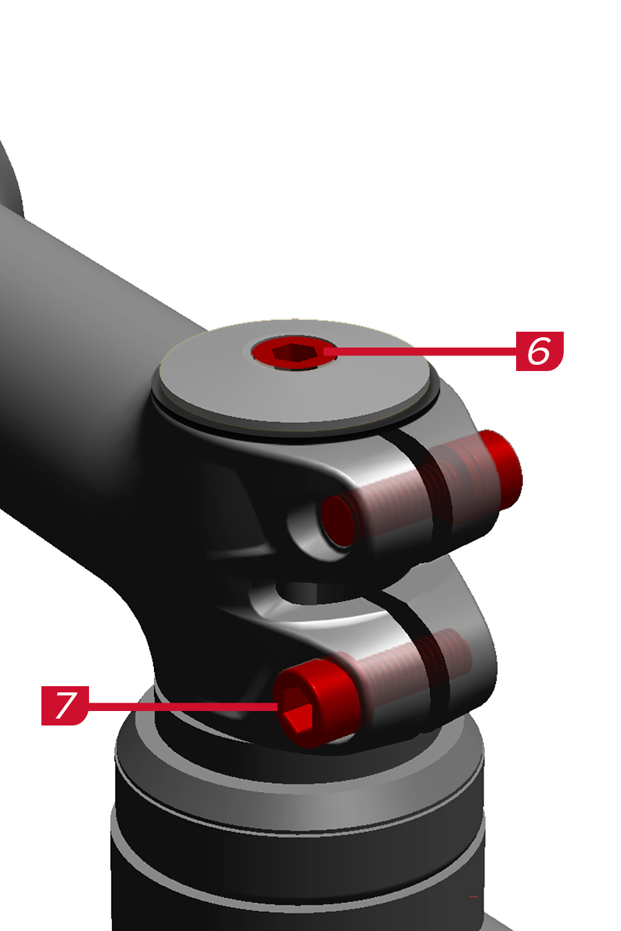
6-7. Install and tighten the stem and headset according to the manufacturer’s instructions.
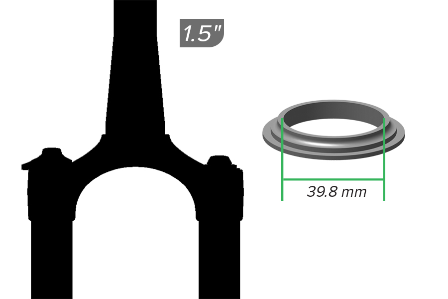
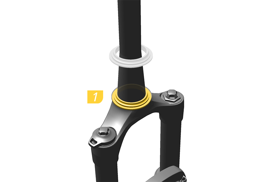
1. Install a headset into the bicycle frame and a crown race onto the fork according to your headset manufacturer’s instructions.
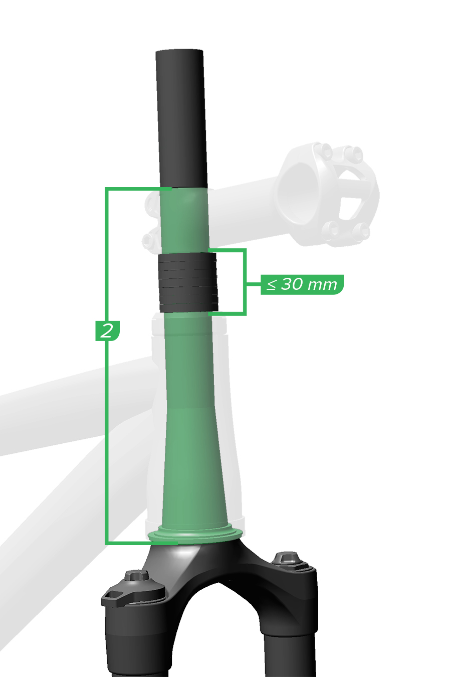
2. Measure the length of the steerer tube from the bottom of the crown race to the top of the stem or any spacers installed above the stem.
No more than 30 mm of spacers should be installed below the stem.
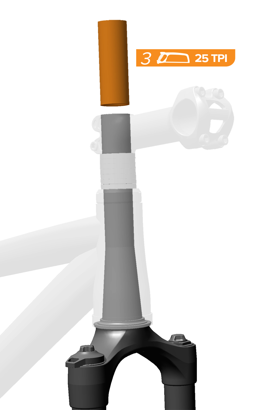
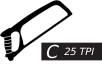
3. Apply masking tape at the cut location to help prevent the carbon from fraying. Mark the cut line, then cut the steerer tube using a hacksaw with a minimum 25 TPI blade and saw guide so that the top of the steerer tube is flush with the top of the stem when installed. Smooth the cut area with 400 grit sandpaper.
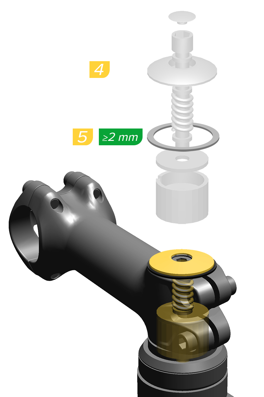
4. Install the fork into the frame and the stem onto the steerer tube.
To allow for proper headset adjustment, a 2 mm or larger spacer must be installed on top of the stem below the topcap.
5. Install a headset compression device into the steerer tube according to the manufacturer’s instructions.
Do not use a star nut.
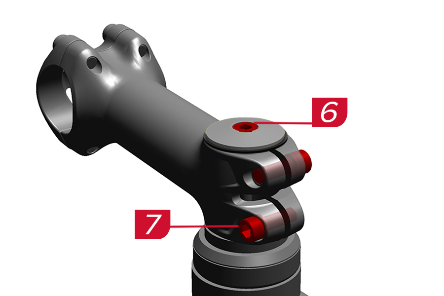
6-7. Install and tighten the stem and headset according to the manufacturer’s instructions.
CRASH HAZARD
Torque: Parts must be tightened to the specified torque. Failure to do so can result in SERIOUS INJURY OR DEATH.
Installation: SRAM recommends that you have your RockShox suspension installed by a qualified bicycle mechanic. Installation requires knowledge of bicycle and suspension components, as well as the use of specialized tools. Incorrect installation can lead to SERIOUS INJURY OR DEATH.
Internal Routing: Confirm internally routed cables, housing or brake hoses do not contact the steerer tube. Any contact may cause abrasions, which over time can cause damage which may result in loss of control, leading to SERIOUS INJURY OR DEATH. Inspect the steerer tube during service intervals to ensure the steerer tube is not worn or damaged. If damaged, replace the crown steerer upper tube prior to riding to avoid SERIOUS INJURY OR DEATH. If resistance is felt while steering, stop riding and confirm the cables, housing, and brake hoses are not making contact with the steerer tube. Eliminate contact prior to riding to avoid SERIOUS INJURY OR DEATH.
Fork Steerer Tube: To avoid steerer tube failure, which can lead to SERIOUS INJURY OR DEATH, do not cut threads into a non-threaded steerer tube.
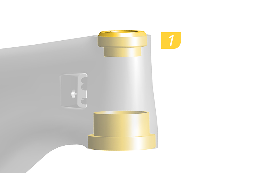
1. Install a headset into the bicycle frame according to your headset manufacturer’s instructions.
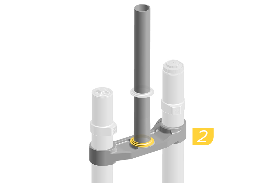
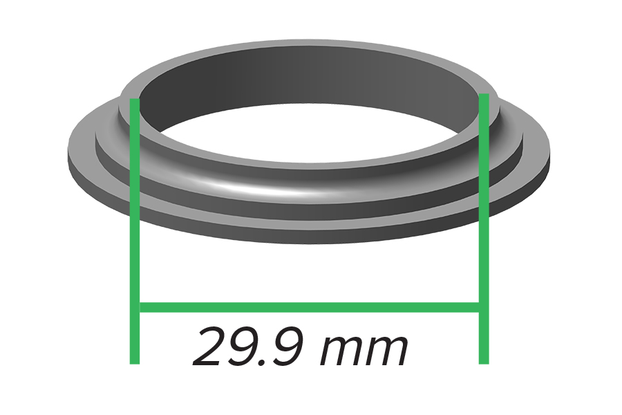
2. Install a 29.9 mm crown race onto the fork according to your headset manufacturer’s instructions.
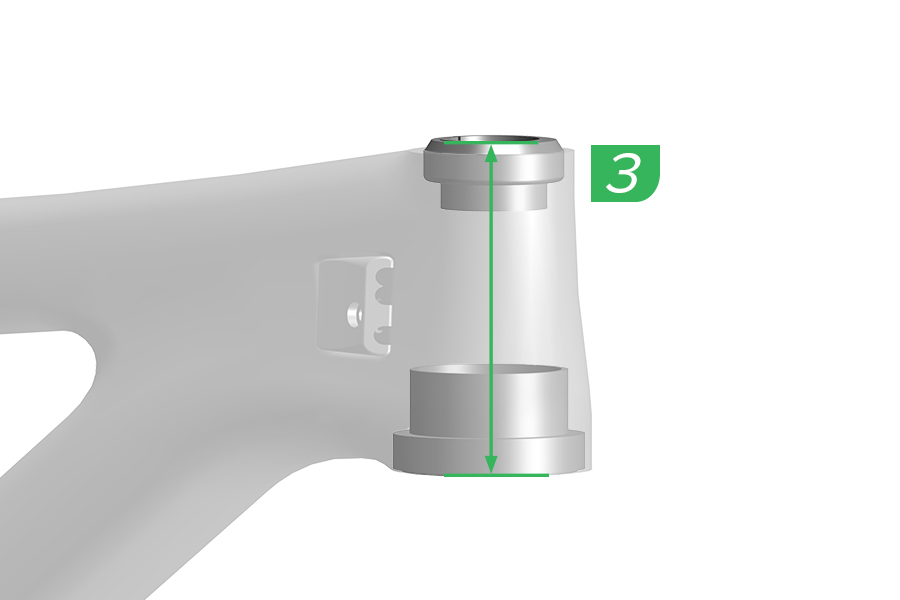
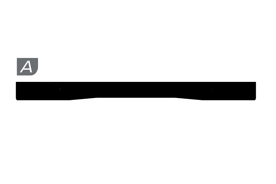
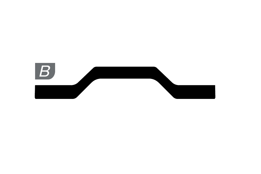
3. Measure the length of the headtube and the installed headset to determine the correct upper crown, (A) short or (B) tall (most common), for your bike.
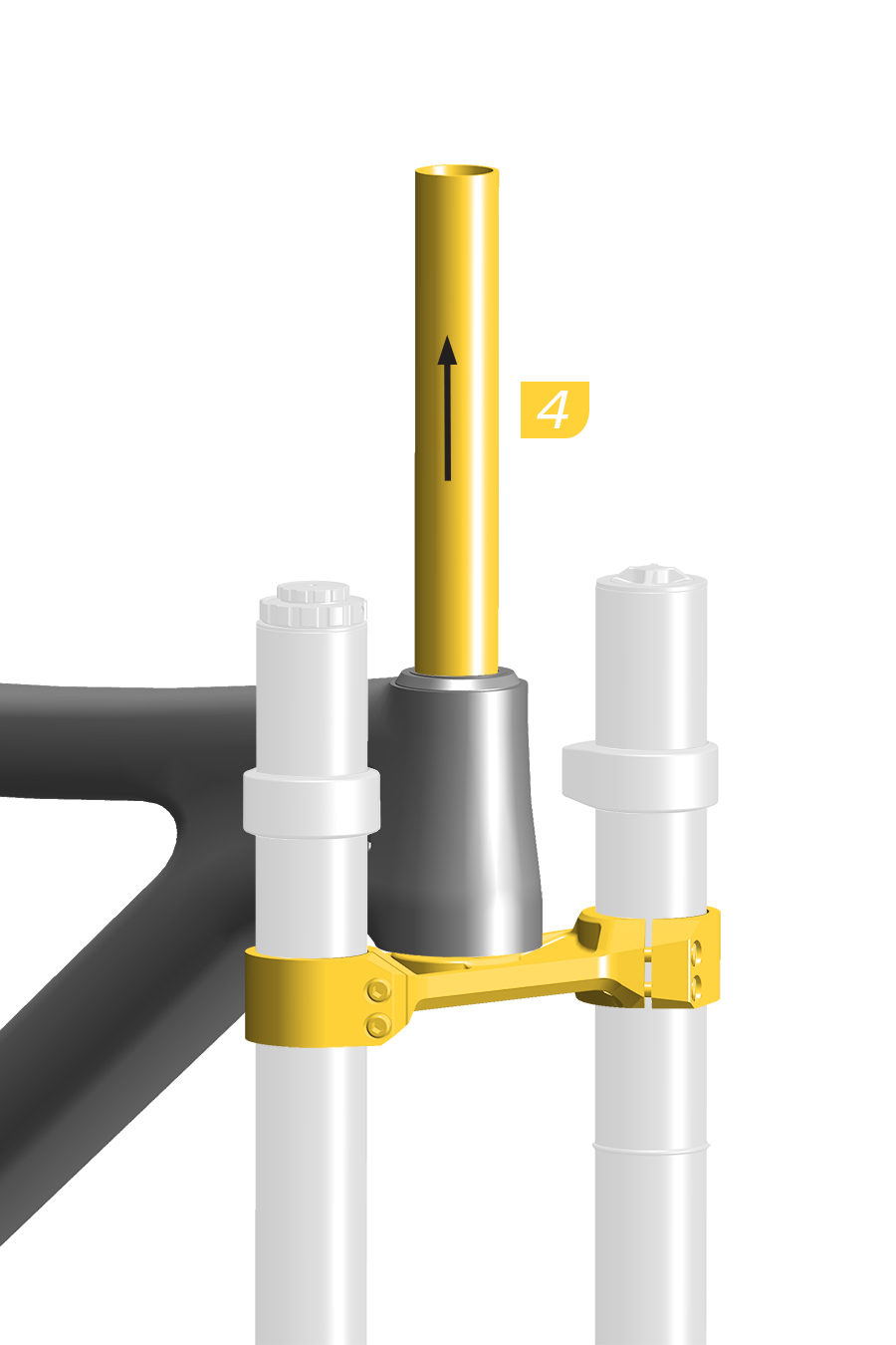
4. Install the fork into the frame.
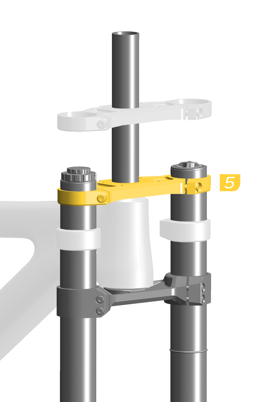
5. Install the upper crown onto the steerer tube and upper tubes. Install a headset spacer under the upper crown if required. Do not tighten any of the upper crown bolts.
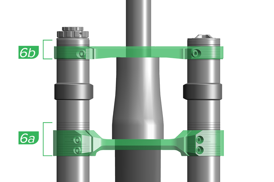
6a. The lower crown must be even on both upper tubes and within the lower crown height gradients.
6b. The bottom edge of the upper crown should be at or above the lowest gradient line on the upper tube, and the top edge of the upper crown should be at or below the top edge of the upper tube. Install a headset spacer under the upper crown if required.
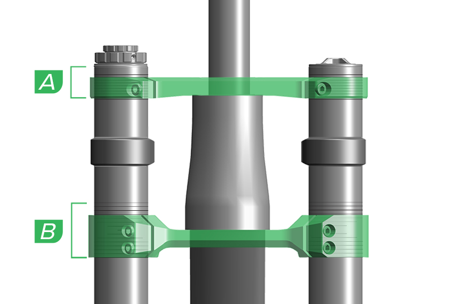
A. Do not position any part of the lower crown outside the lower crown height gradients. B. Do not position any part of the upper crown below the lowest crown height gradient on the upper tube, or above the top edge of each upper tube.
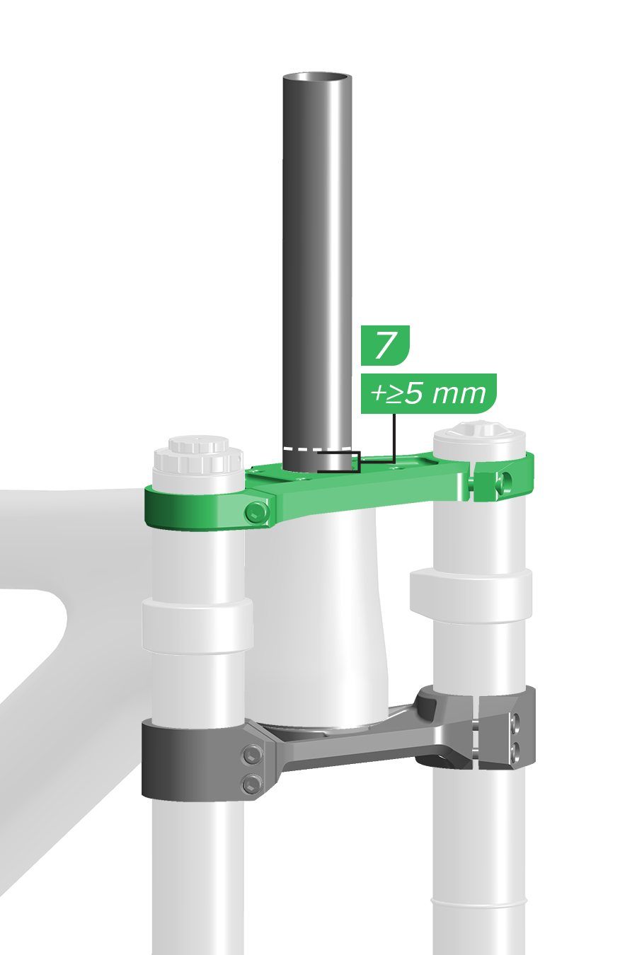
7. Measure and mark the steerer tube with a cut line at least 5 mm above the top of the upper crown.
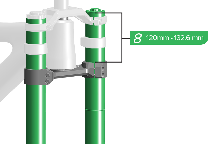
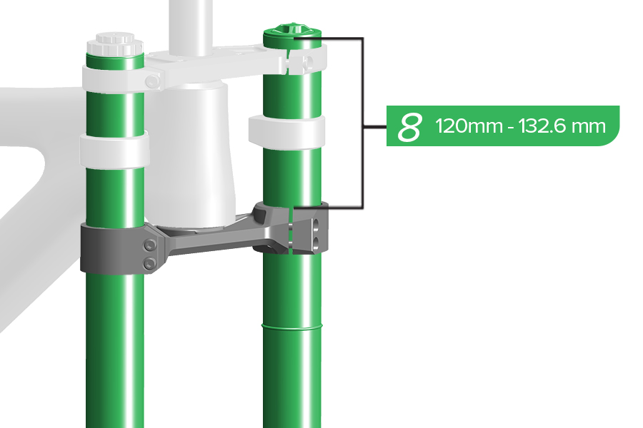
8. Measure from the top of the upper tube to the top of the lower crown and confirm the measurement is within specification. Both upper tubes must be installed evenly at the same height.
The length of the upper tubes measured from the top of the upper tube to the top of the lower crown must be not less than 120 mm and not greater than 132.6 mm. Tire contact with the lower crown while riding may cause damage to the fork, and may result in loss of control and serious injury to the rider.
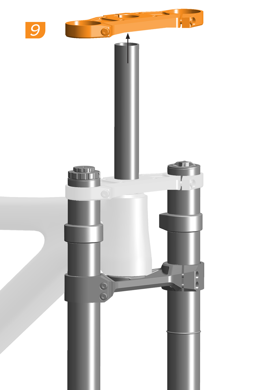
9. Remove the upper crown and headset spacer(s), if installed.
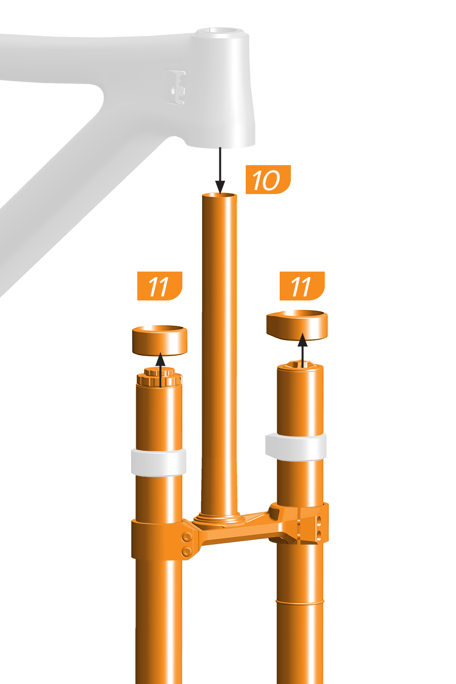
10. Remove the fork from the frame.
11. Remove the frame bumpers, if installed.
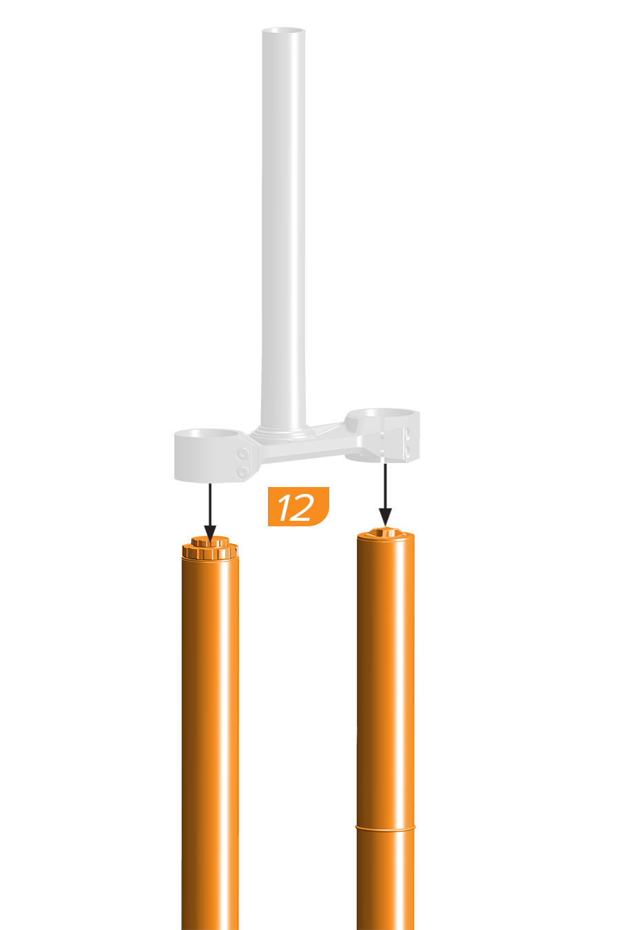
12. Remove the upper tubes from the lower crown before cutting the steerer tube.
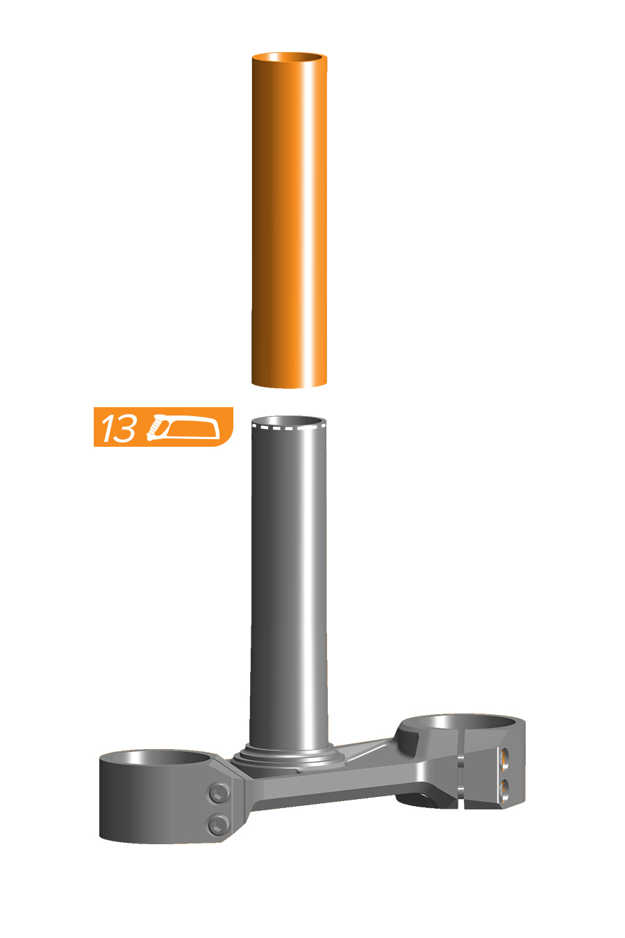
13. Use a hacksaw and saw guide to cut the steerer tube. Smooth the cut area with 400 grit sandpaper or a file.
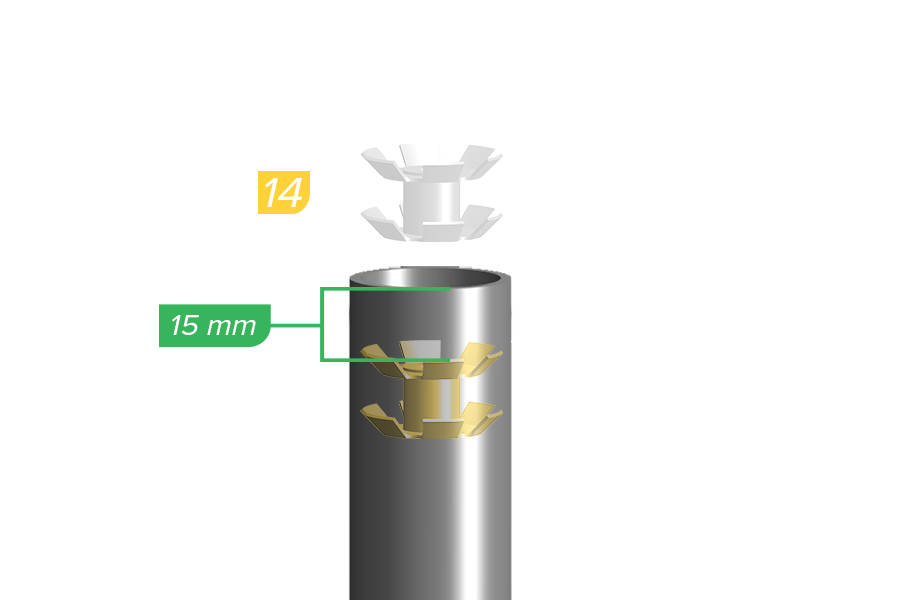
14. Use a star nut tool to install a star nut into the steerer tube.
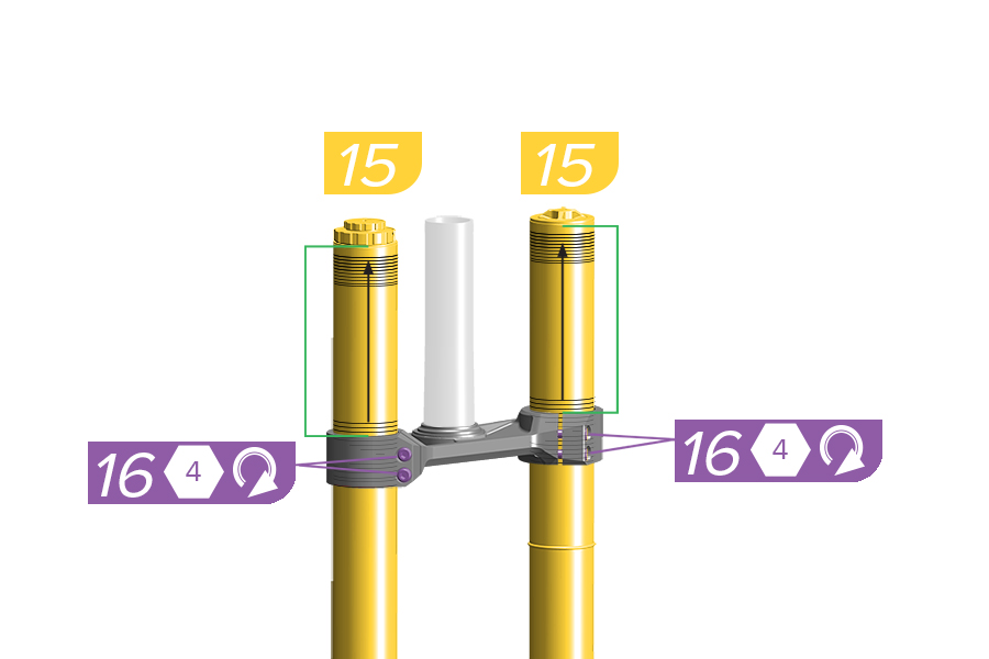
15. Install each upper tube into the lower crown in the original position, evenly within the lower crown height gradients on the upper tubes.
16. Tighten the crown bolts finger tight.
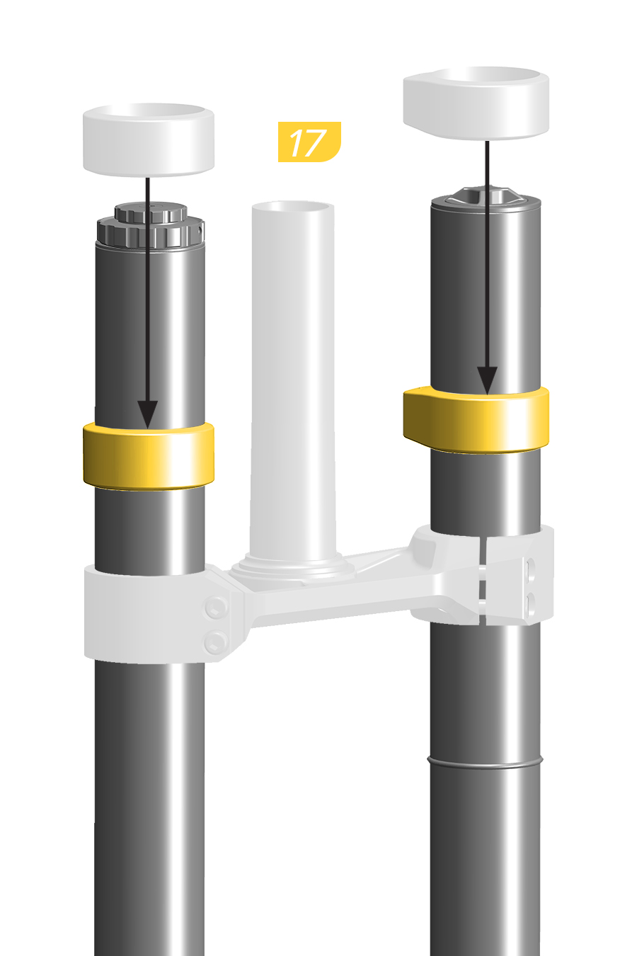
17. Install the bumpers onto the upper tubes.
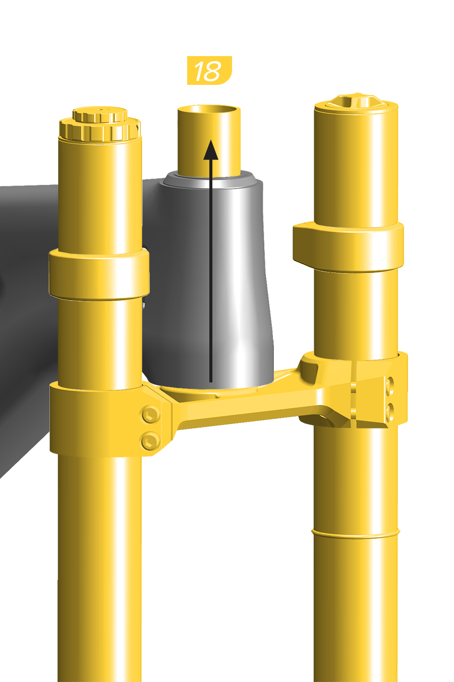
18. Install the fork into the frame.
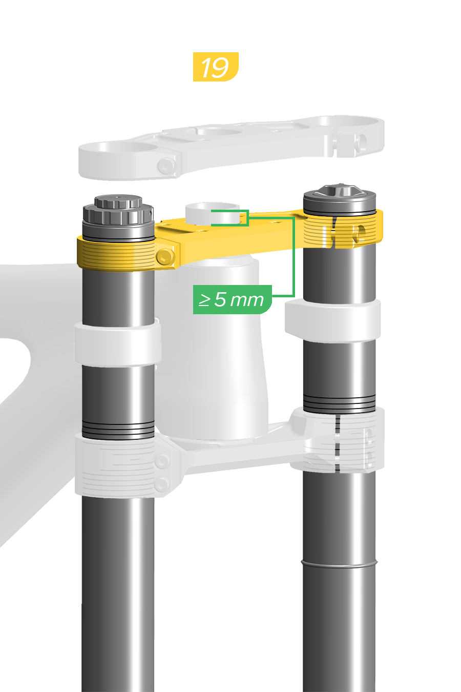
19. Install a headset spacer if required. Install the upper crown onto the steerer tube and upper tubes. Do not tighten the upper crown bolts. The steerer tube must extend above the upper crown a minimum of 5 mm.
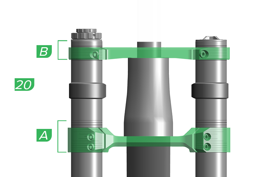
20. Confirm the upper and lower crowns are even and are in the correct position on each upper tube.
A. Do not position any part of the lower crown outside the lower crown height gradients. B. Do not position any part of the upper crown below the lowest crown height gradient on the upper tube, or above the top edge of each upper tube.
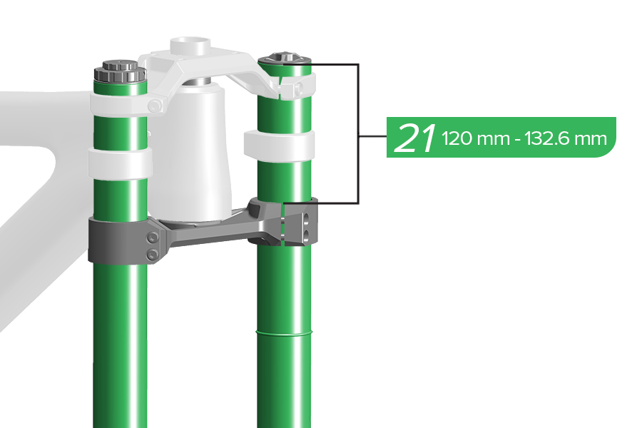
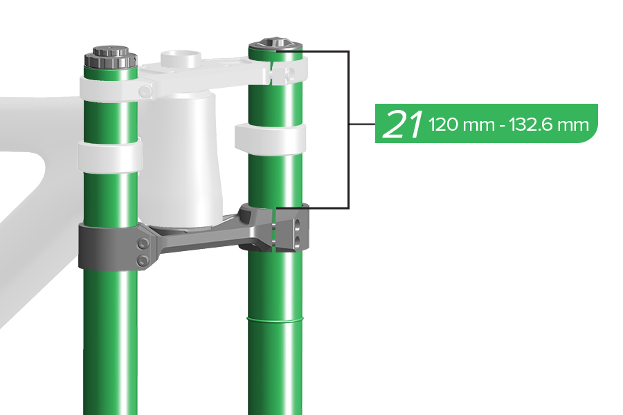
21. Measure from the top of the upper tube to the top of the lower crown and confirm the measurement is within specification. Both upper tubes must be installed evenly at the same height.
The length of the upper tubes measured from the top of the upper tube to the top of the lower crown must be not less than 120 mm and not greater than 132.6 mm. Tire contact with the lower crown while riding may cause damage to the fork, and may result in loss of control and serious injury to the rider.
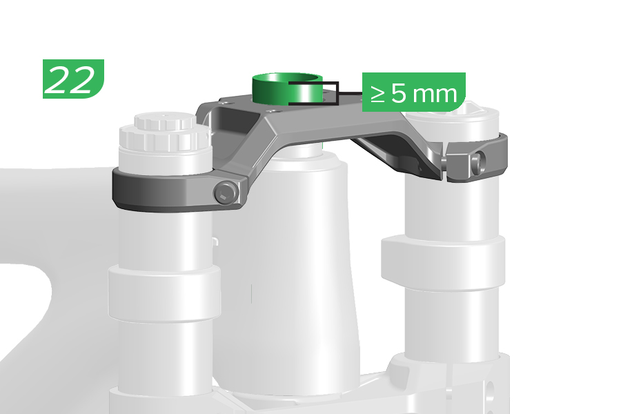
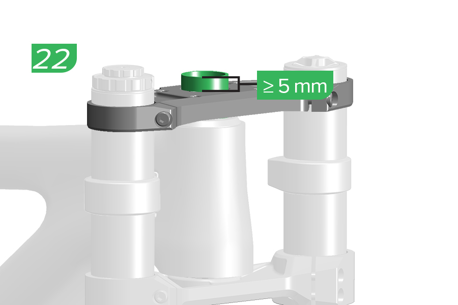
22. Measure from the top of the upper crown to the end of the steerer tube and confirm the measurement is within specification.
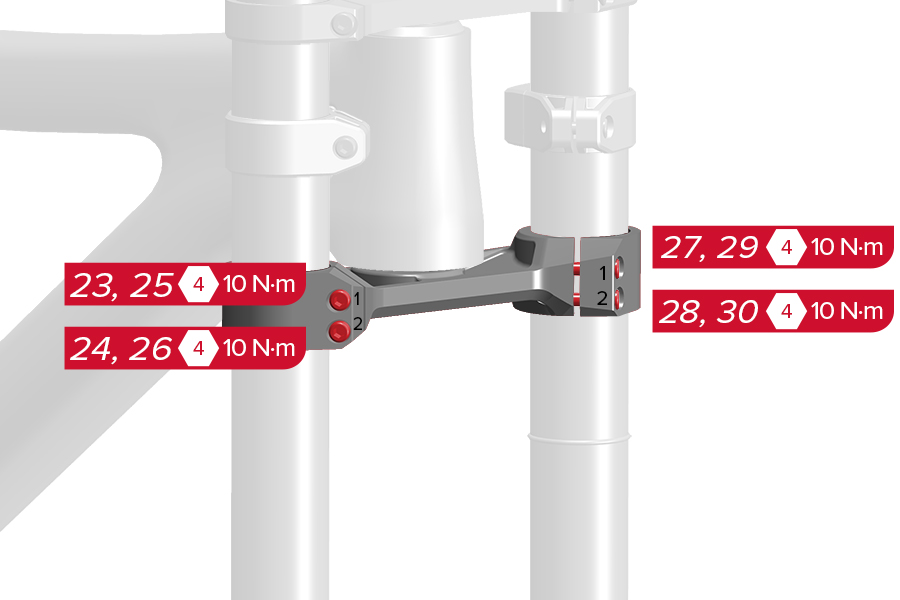
23-26. Damper Side: Tighten the lower crown bolts, top bolt first, lower bolt second. Repeat this sequence once more.
27-30. Spring Side: Tighten the lower crown bolts, top bolt first, lower bolt second. Repeat this sequence once more.
CRASH HAZARD: Tighten the crown bolts in the correct order and to the specified torque. Failure to do so can result in SERIOUS INJURY OR DEATH.
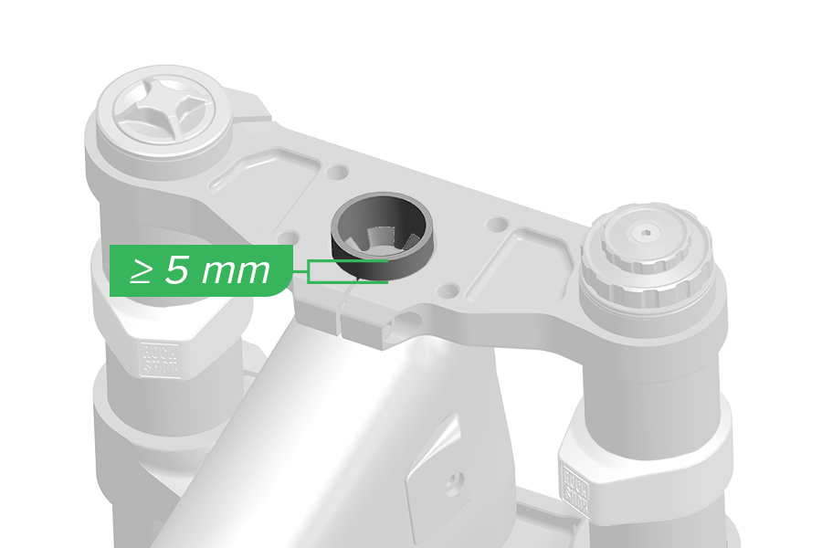
At least 5 mm of steerer tube should be exposed above the top of the upper crown.
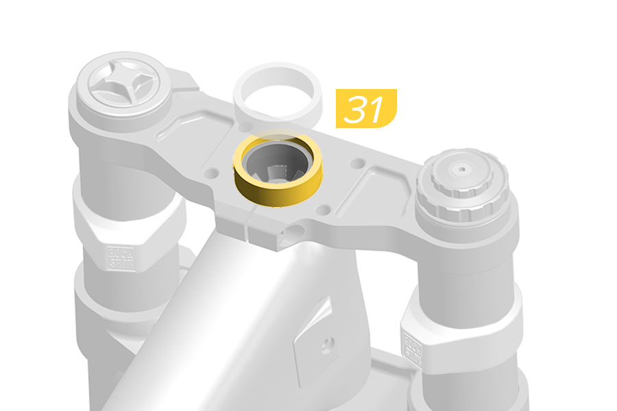
31. Install a headset spacer(s), onto the steerer tube, that is at least 3-4 mm above the top of the cut steerer tube.
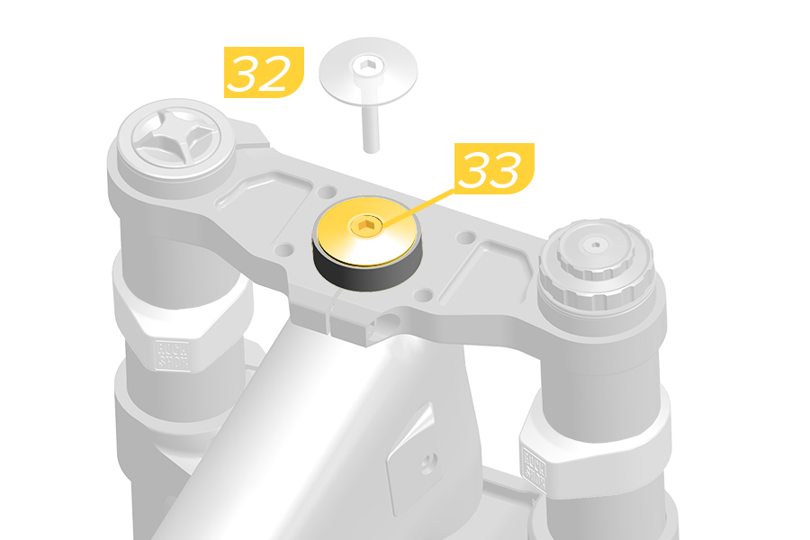
32. Install the headset top cap.
33. Thread the bolt into the star nut and tighten it finger tight. Do not fully tighten the bolt before upper tube alignment has been performed.
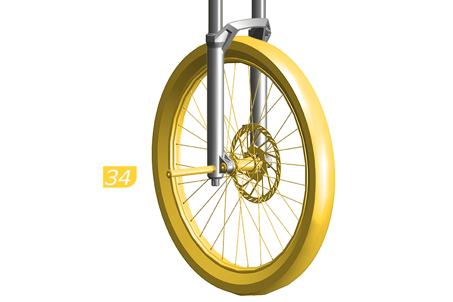
Set upper tube alignment before tightening the upper crown bolts. This will eliminate any twist or misalignment before tightening the upper crown bolts.
34. Install the front wheel and Maxle DH.
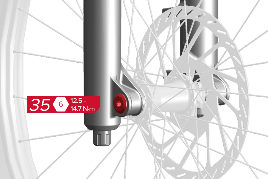
35. Tighten the Maxle DH (drive side).
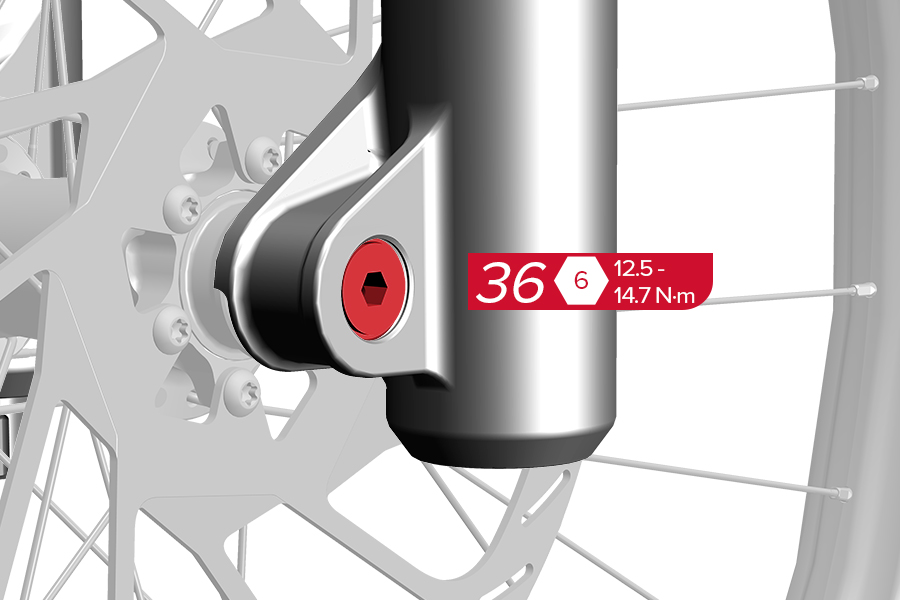
36. Tighten the Maxle DH (non-drive side).
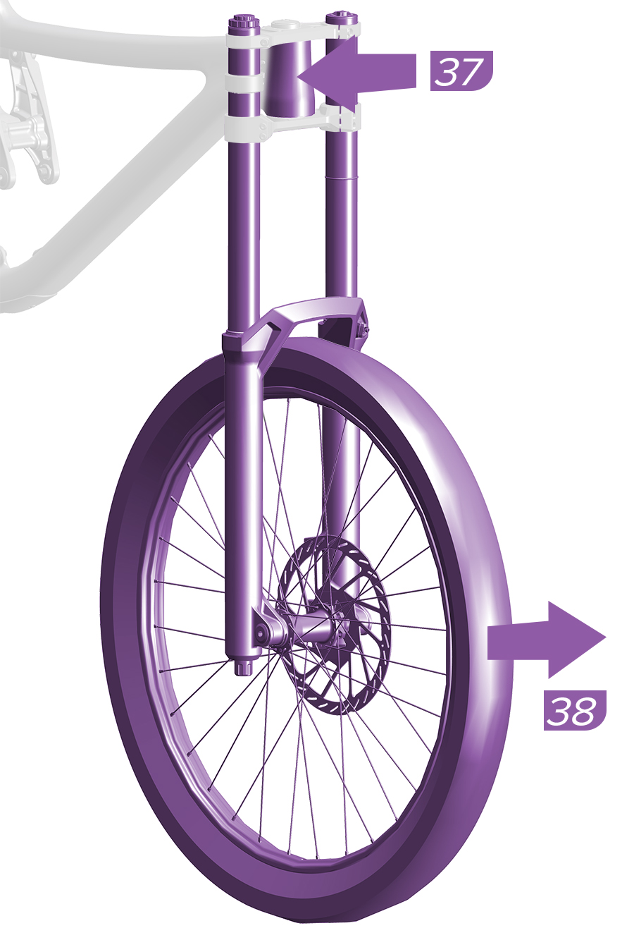
37. With the fork centered, grip the frame head tube with one hand, and the front wheel with other hand.
38. Quickly and firmly, pull the front wheel forward while applying opposing pressure to the headtube to properly align the upper tubes squarely and evenly in the crowns. Do not remove the wheel.
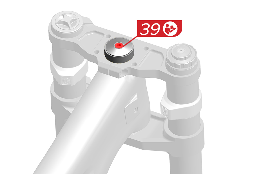
39. Tighten the headset top cap bolt according to the headset manufacturer's instructions.
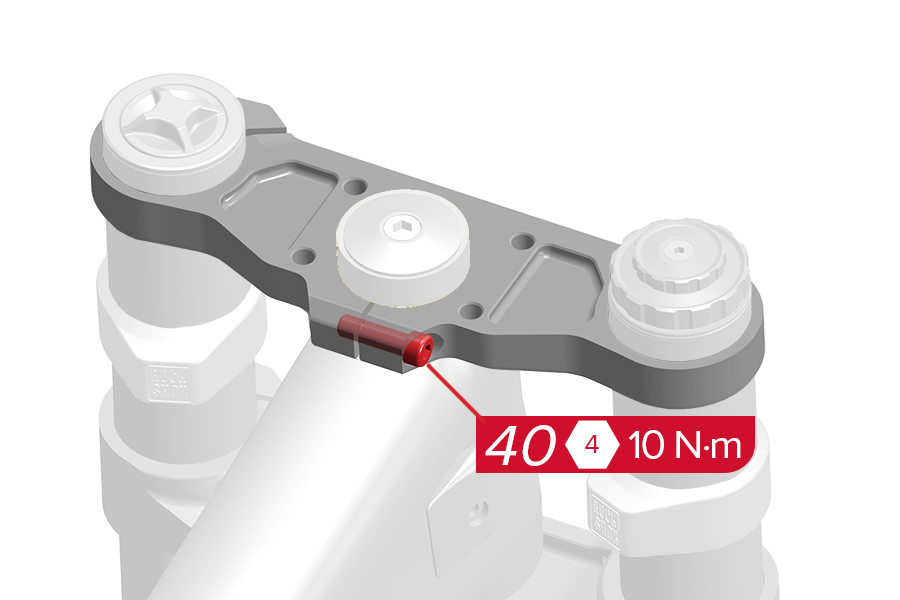
40. Tighten the upper crown steerer tube clamp bolt.
Do not tighten the upper crown steerer tube clamp bolt before the headset top cap is installed.
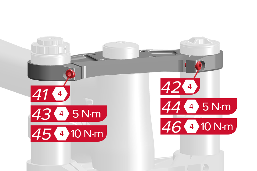
Tighten the upper crown bolts.
41. Tighten the damper side bolt finger tight. 42. Tighten the spring side bolt finger tight.
43. Tighten the damper side bolt to 5 N·m. 44. Tighten the spring side bolt to 5 N·m.
45. Tighten the damper side bolt to 10 N·m. 46. Tighten the spring side bolt to 10 N·m.
CRASH HAZARD: Tighten the crown bolts in the correct order and to the specified torque. Failure to do so can result in SERIOUS INJURY OR DEATH.
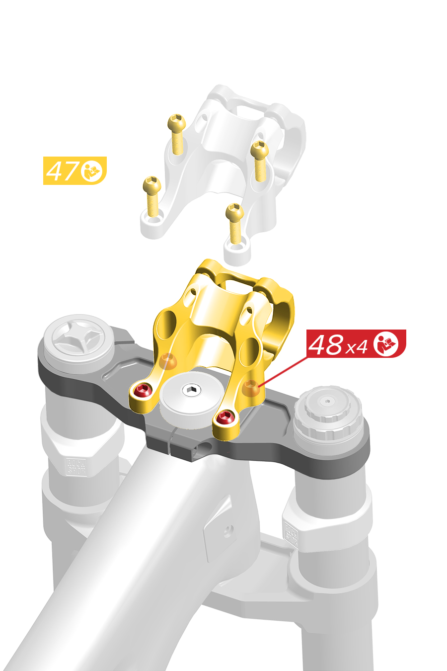
47-48. Install the direct mount stem onto the upper crown according to the stem manufacturer’s instructions.
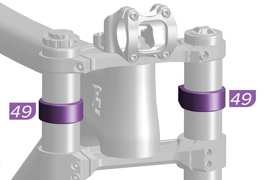
49. Adjust the position of each frame bumper as needed.
.jpg)
1. Install a headset into the bicycle frame according to your headset manufacturer’s instructions.
.jpg)
.1.jpg)
2. Install a 29.9 mm crown race onto the fork according to your headset manufacturer’s instructions.
.jpg)
.jpg)
.jpg)
3. Measure the length of the headtube and the installed headset to determine the correct upper crown, (A) short or (B) tall (most common), for your bike.
.jpg)
4. Install the fork into the frame.
.jpg)
5. Install the upper crown onto the steerer tube and upper tubes. Install a headset spacer under the upper crown if required. Do not tighten any of the upper crown bolts.
.jpg)
6a. The lower crown must be even on both upper tubes and within the lower crown height gradients.
6b. The bottom edge of the upper crown should be at or above the lowest gradient line on the upper tube, and the top edge of the upper crown should be at or below the top edge of the upper tube. Install a headset spacer under the upper crown if required.
.jpg)
A. Do not position any part of the lower crown outside the lower crown height gradients. B. Do not position any part of the upper crown below the lowest crown height gradient on the upper tube, or above the top edge of each upper tube.
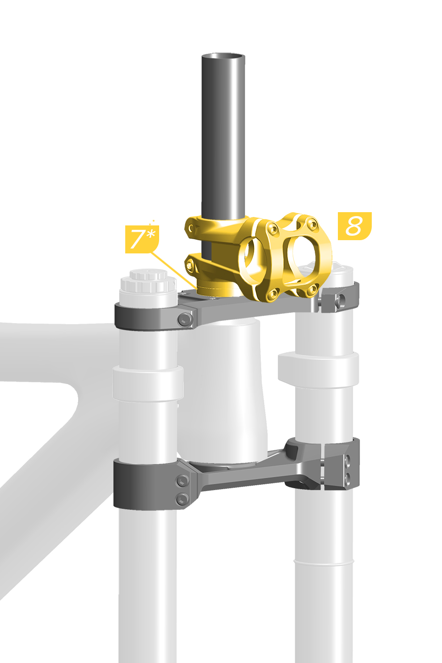
7*. Optional - Install a headset spacer below the stem and above the upper crown.
8. Install the stem.
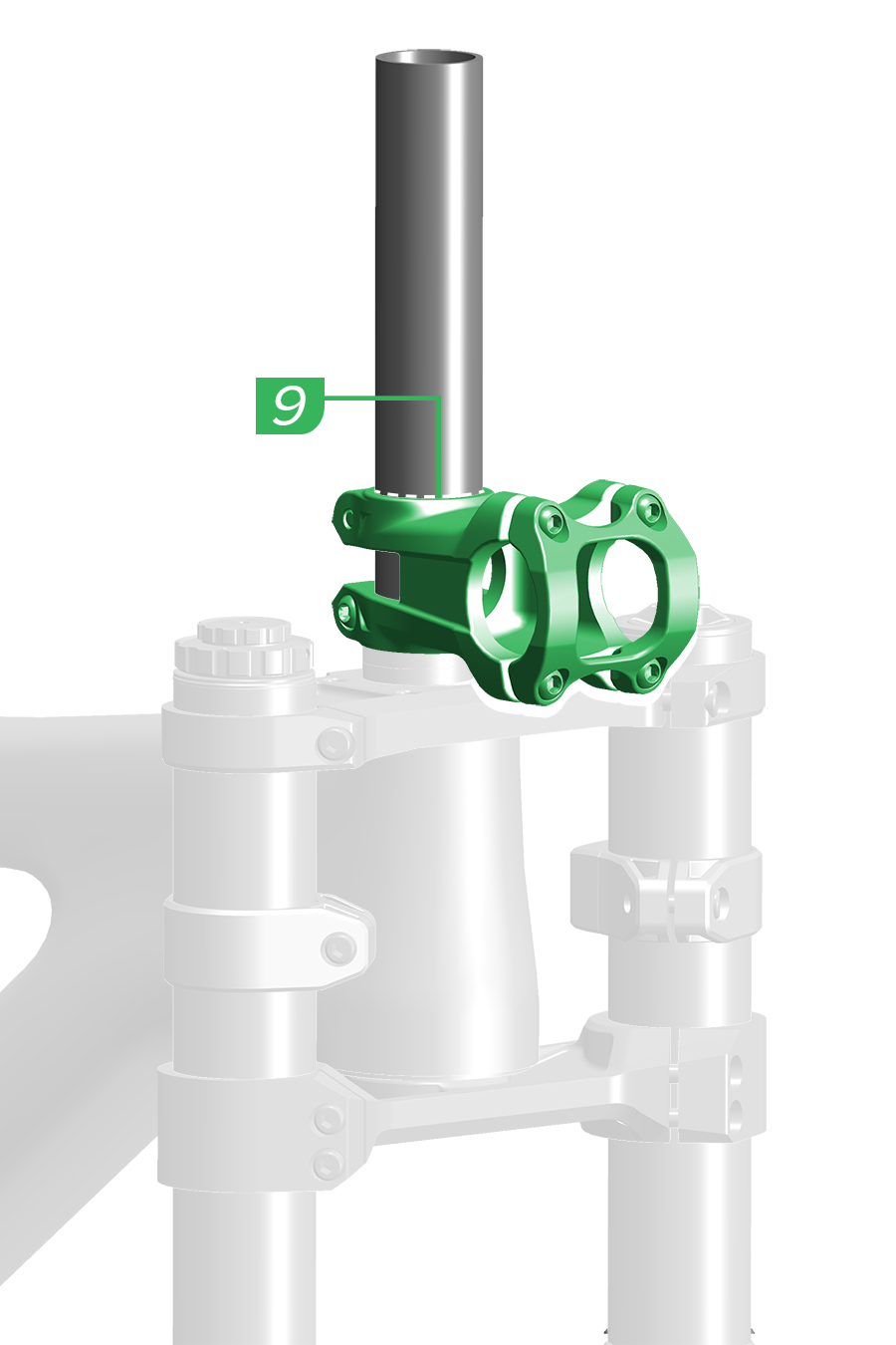
9. Mark a line on the steerer tube at the top of the stem.
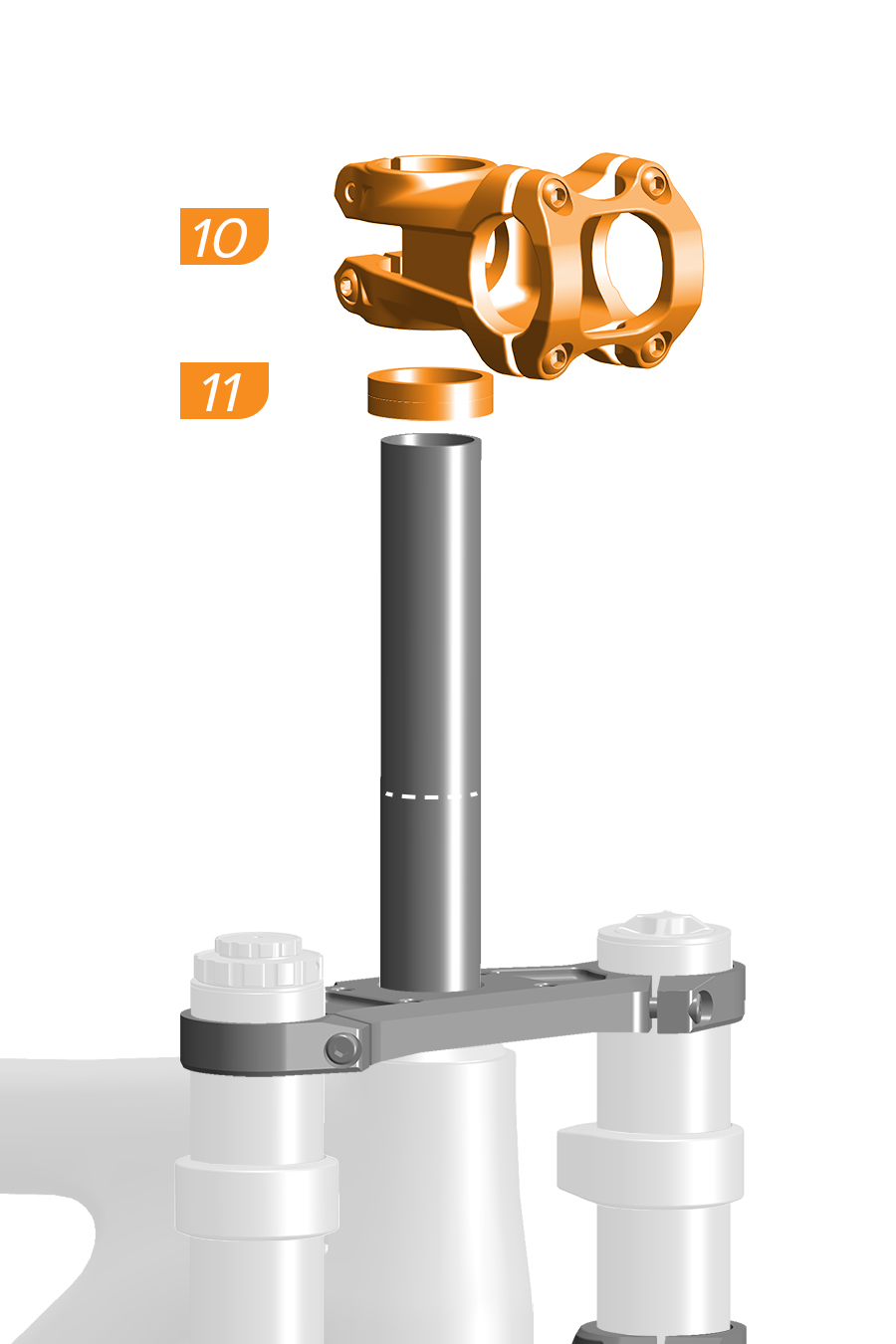
10. Remove the stem.
11. Remove the headset spacer (if installed).
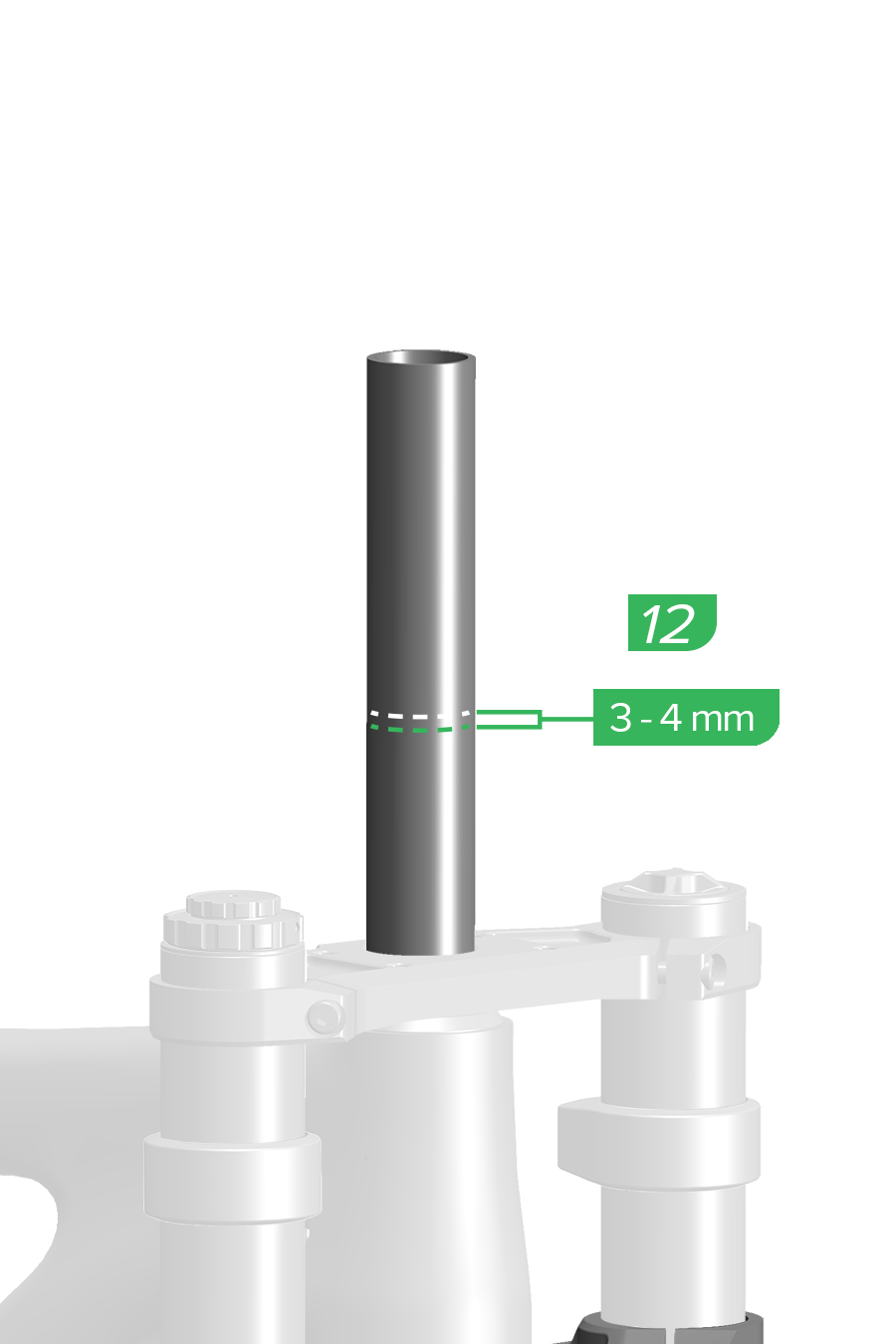
12. Measure and mark the steerer tube with a cut line 3-4 mm below the marked stem line.
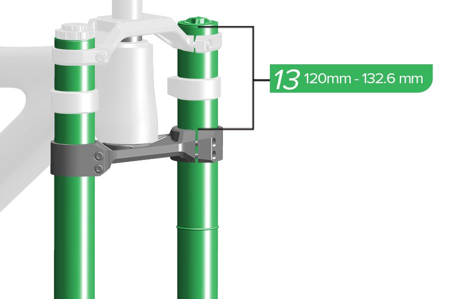
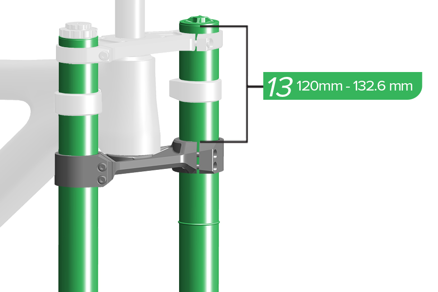
13. Measure from the top of the upper tube to the top of the lower crown and confirm the measurement is within specification. Both upper tubes must be installed evenly at the same height.
The length of the upper tubes measured from the top of the upper tube to the top of the lower crown must be not less than 120 mm and not greater than 132.6 mm. Tire contact with the lower crown while riding may cause damage to the fork, and may result in loss of control and serious injury to the rider.
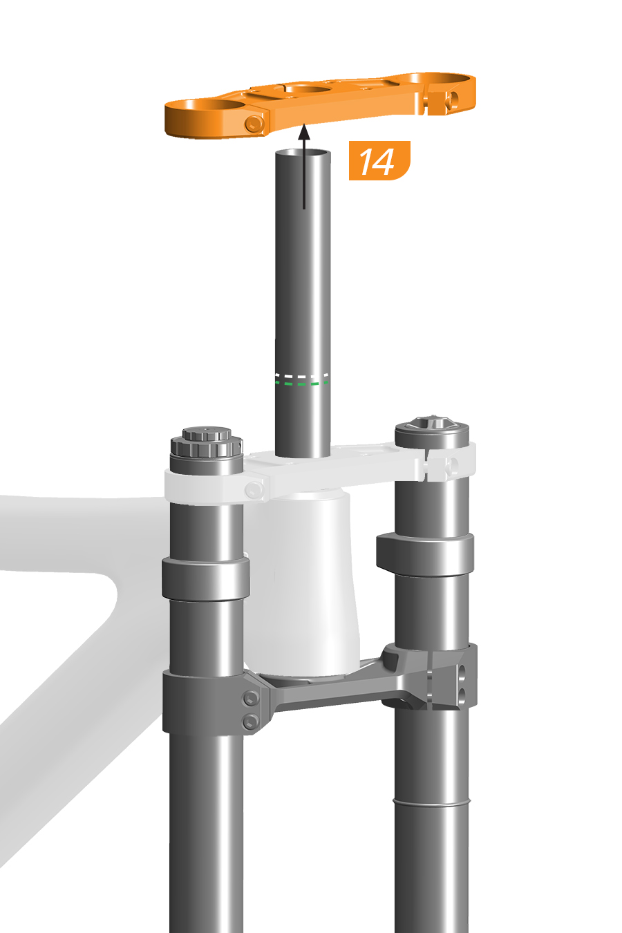
14. Remove the upper crown and headset spacer(s), if installed.
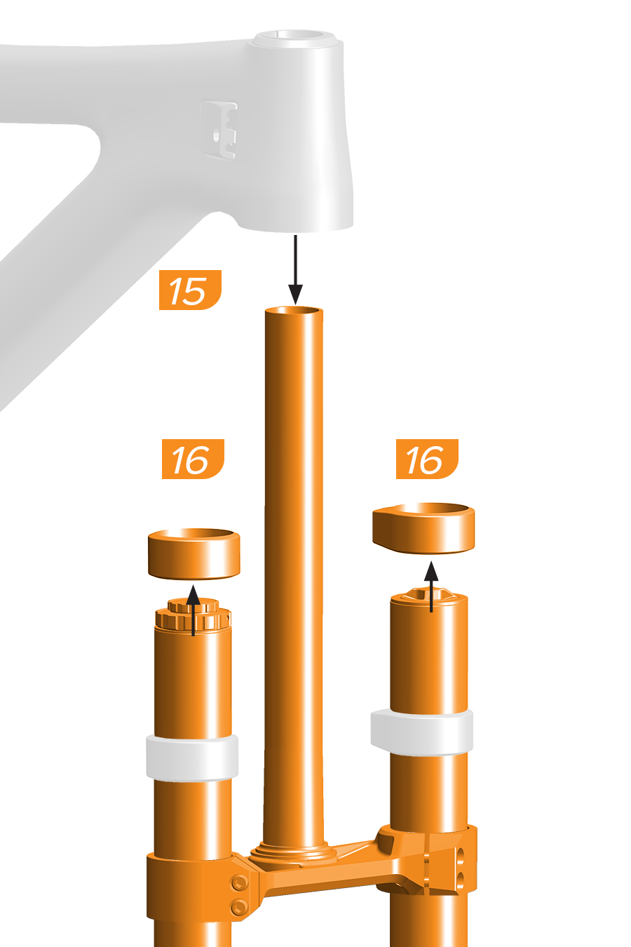
15. Remove the fork from the frame.
16. Remove the frame bumpers, if installed.
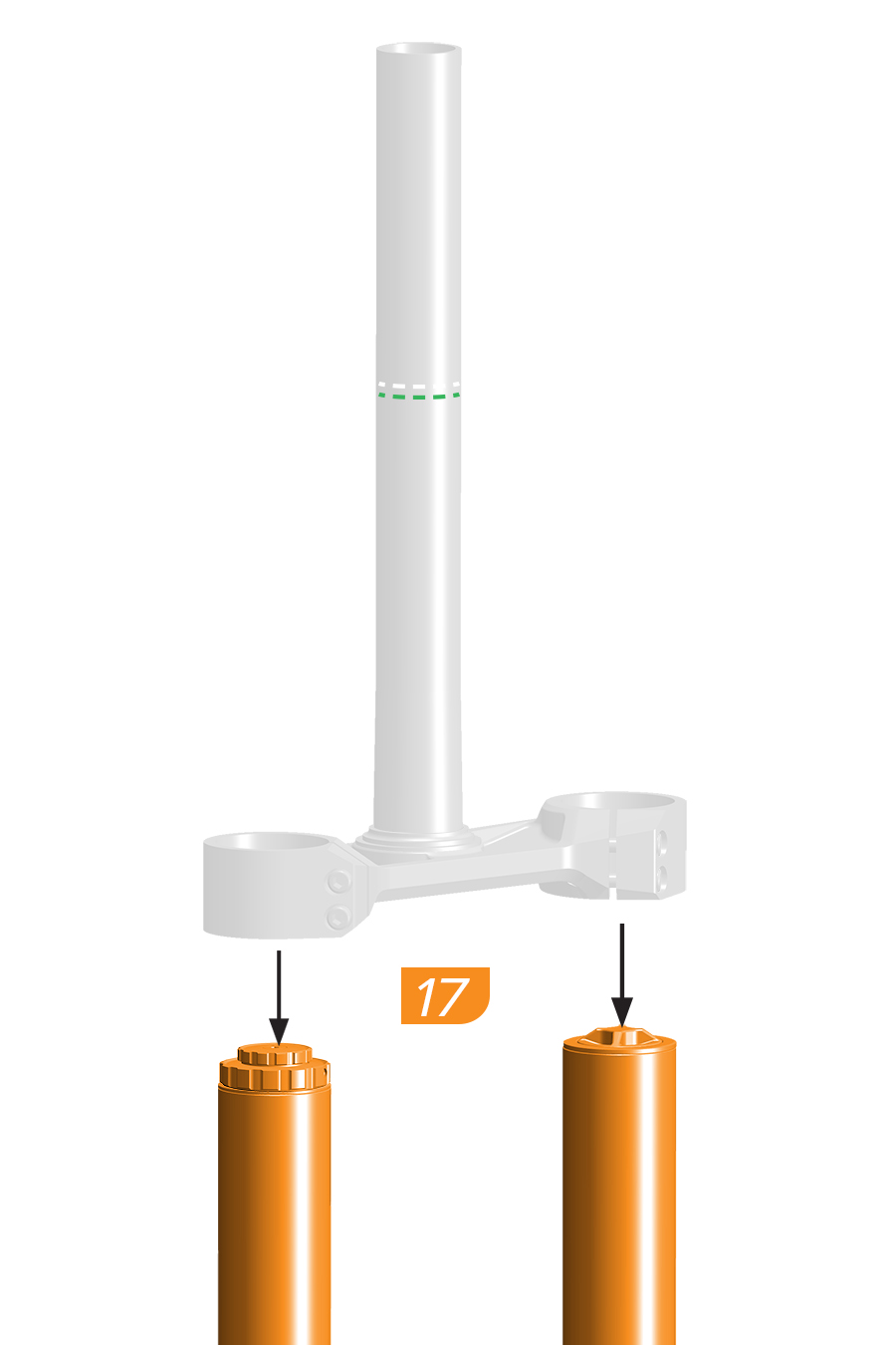
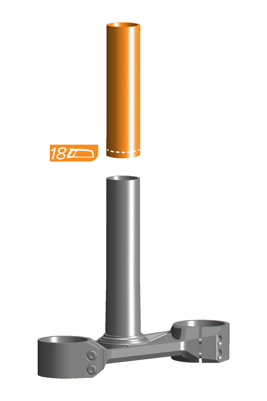
18. Use a hacksaw and saw guide to cut the steerer tube. Smooth the cut area with 400 grit sandpaper or a file.
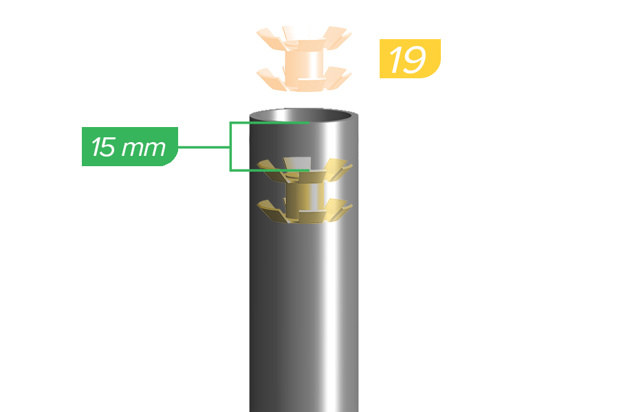
19. Use a star nut tool to install a star nut into the steerer tube.
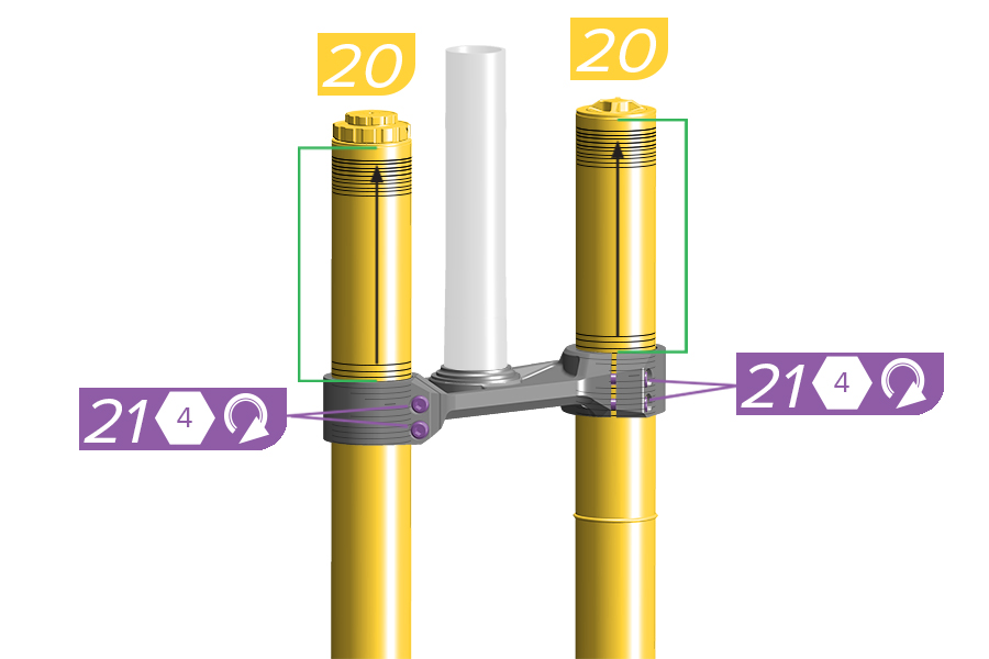
20. Install each upper tube into the lower crown in the original position, evenly within the lower crown height gradients on the upper tubes.
21. Tighten the crown bolts finger tight.
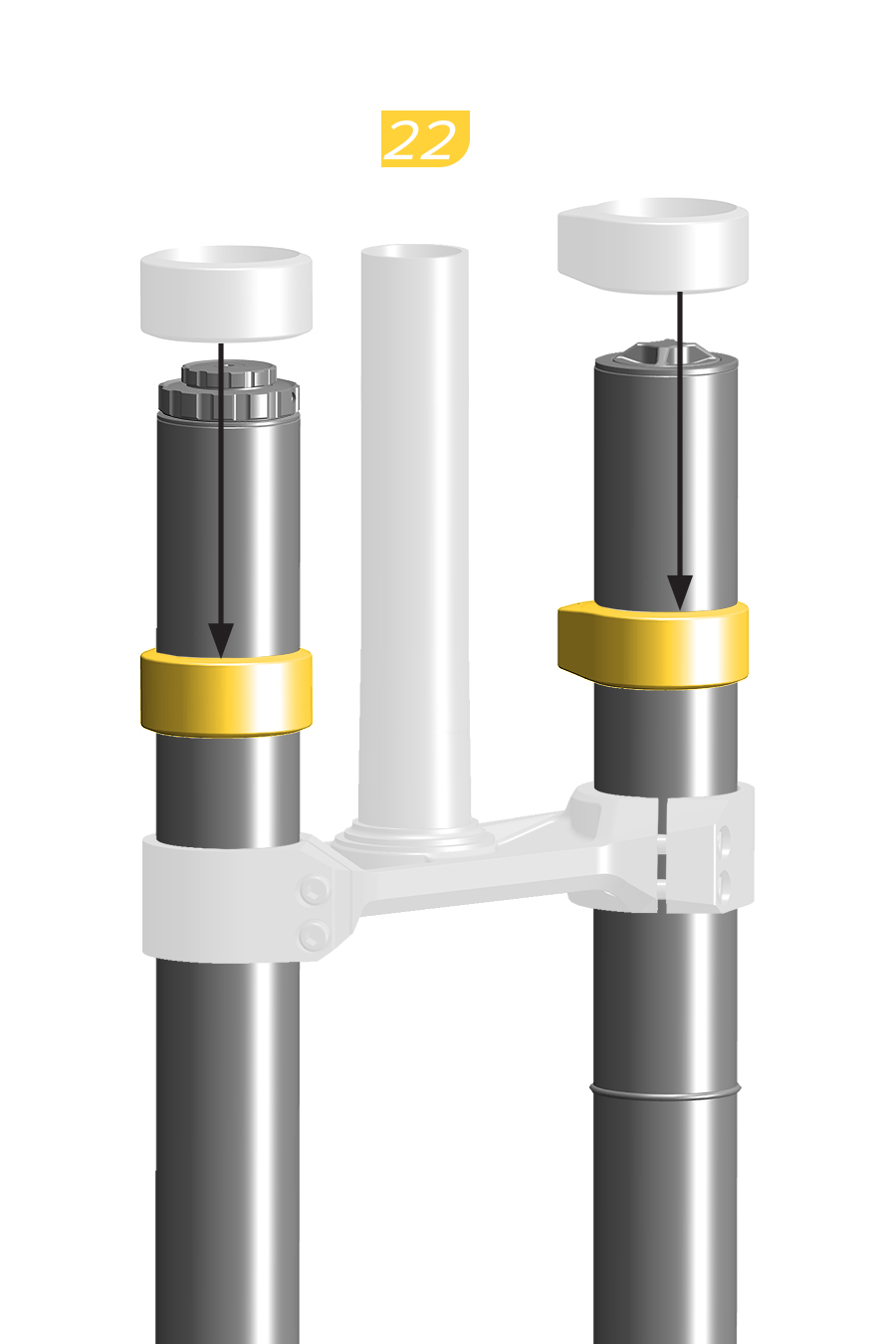
22. Install the bumpers onto the upper tubes.
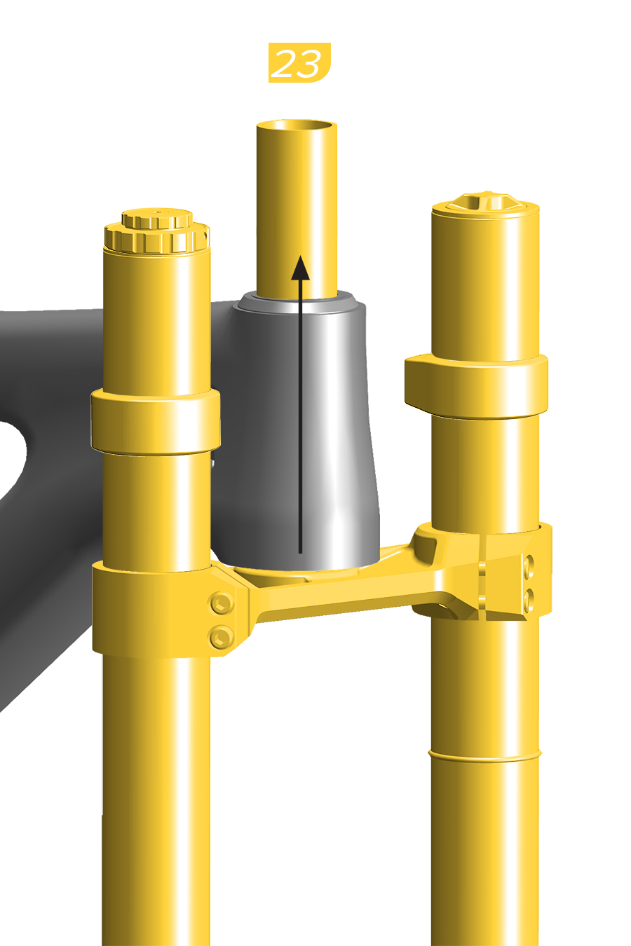
23. Install the fork into the frame.
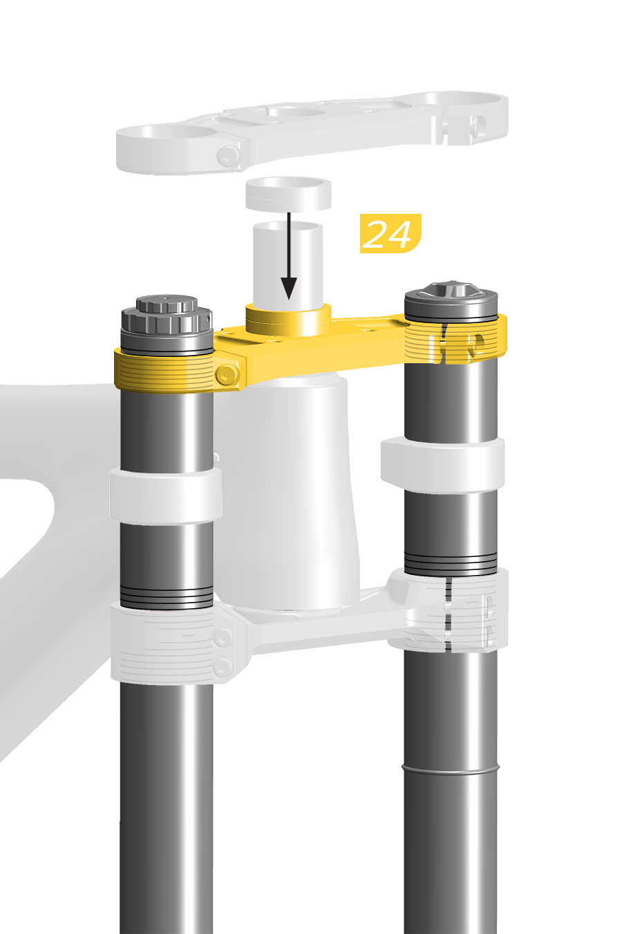
24. Install the upper crown onto the steerer tube and upper tubes. Install a headset spacer(s) if the cut line was measured with a spacer under the stem. Do not tighten the upper crown bolts.
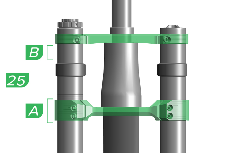
25. Confirm the upper and lower crowns are even and are in the correct position on each upper tube.
A. Do not position any part of the lower crown outside the lower crown height gradients. B. Do not position any part of the upper crown below the lowest crown height gradient on the upper tube, or above the top edge of each upper tube.
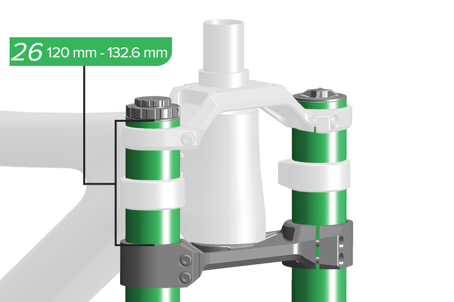
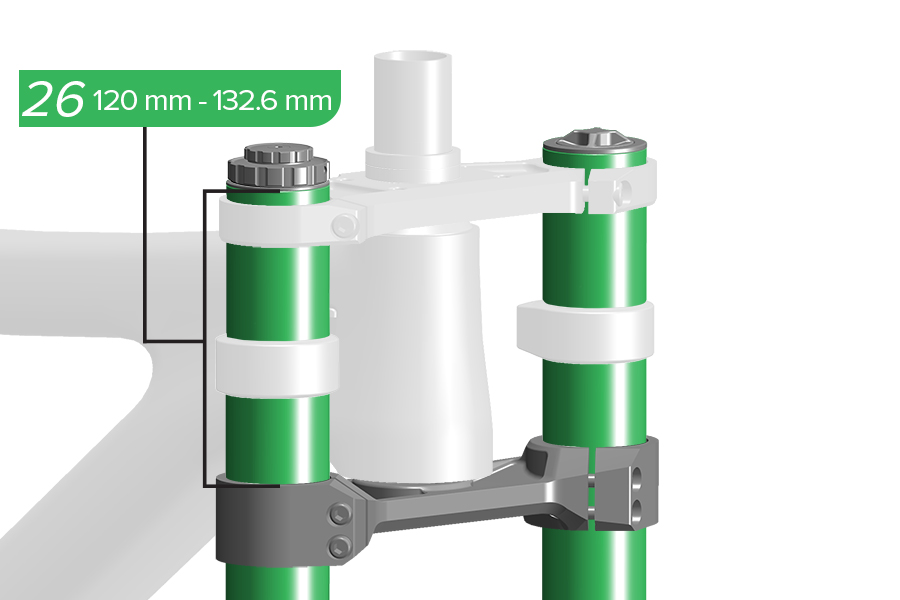
26. Measure from the top of the upper tube to the top of the lower crown and confirm the measurement is within specification. Both upper tubes must be installed evenly at the same height.
The length of the upper tubes measured from the top of the upper tube to the top of the lower crown must be not less than 120 mm and not greater than 132.6 mm. Tire contact with the lower crown while riding may cause damage to the fork, and may result in loss of control and serious injury to the rider.
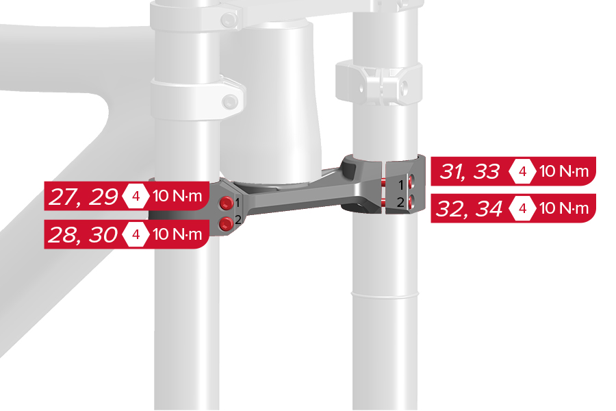
27-30. Damper Side: Tighten the lower crown bolts, top bolt first, lower bolt second. Repeat this sequence once more.
31-34. Spring Side: Tighten the lower crown bolts, top bolt first, lower bolt second. Repeat this sequence once more.
CRASH HAZARD: Tighten the crown bolts in the correct order and to the specified torque. Failure to do so can result in SERIOUS INJURY OR DEATH.
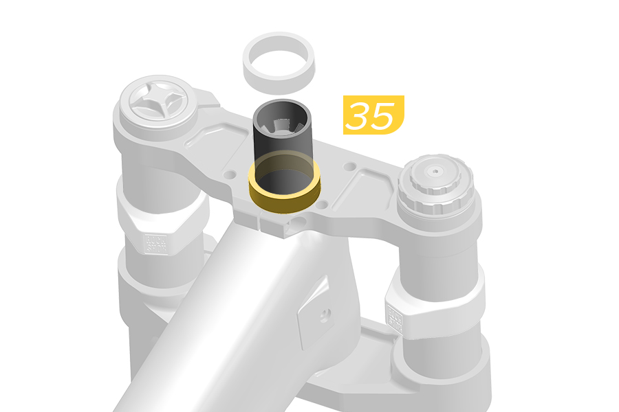
35. Install the same headset spacer (if steerer tube cut was measured with spacer).
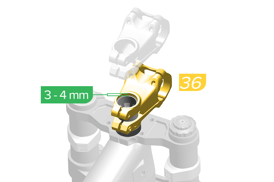
36. Install the stem. The top of the stem should be 3 - 4 mm above the top of the cut steerer tube.
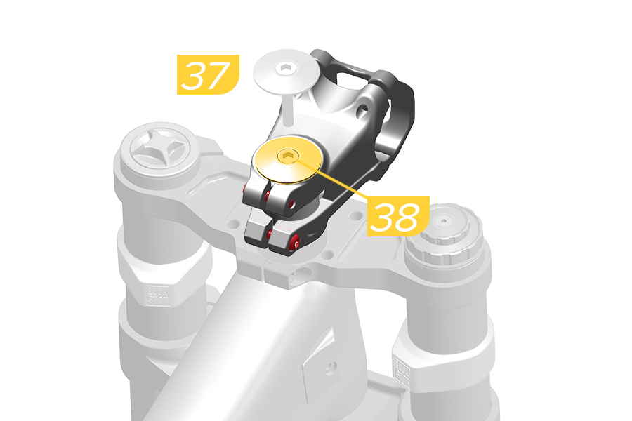
37. Install the headset top cap.
38. Thread the bolt into the star nut and tighten it finger tight. Do not fully tighten the bolt before upper tube alignment has been performed.
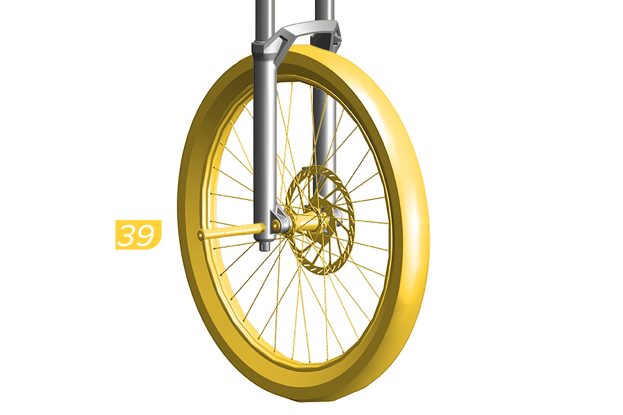
Set upper tube alignment before tightening the upper crown bolts. This will eliminate any twist or misalignment before tightening the upper crown bolts.
39. Install the front wheel and Maxle DH.
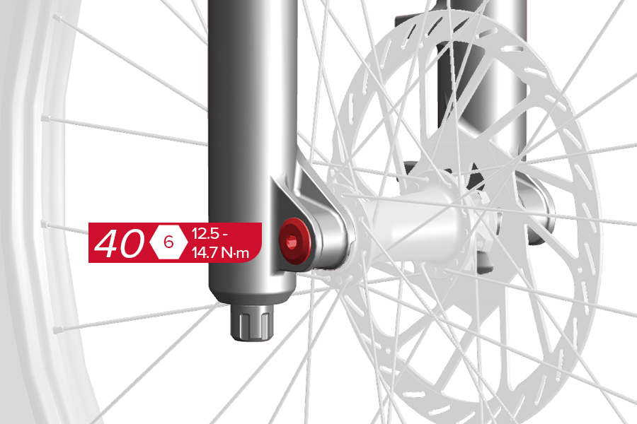
40. Tighten the Maxle DH (drive side).
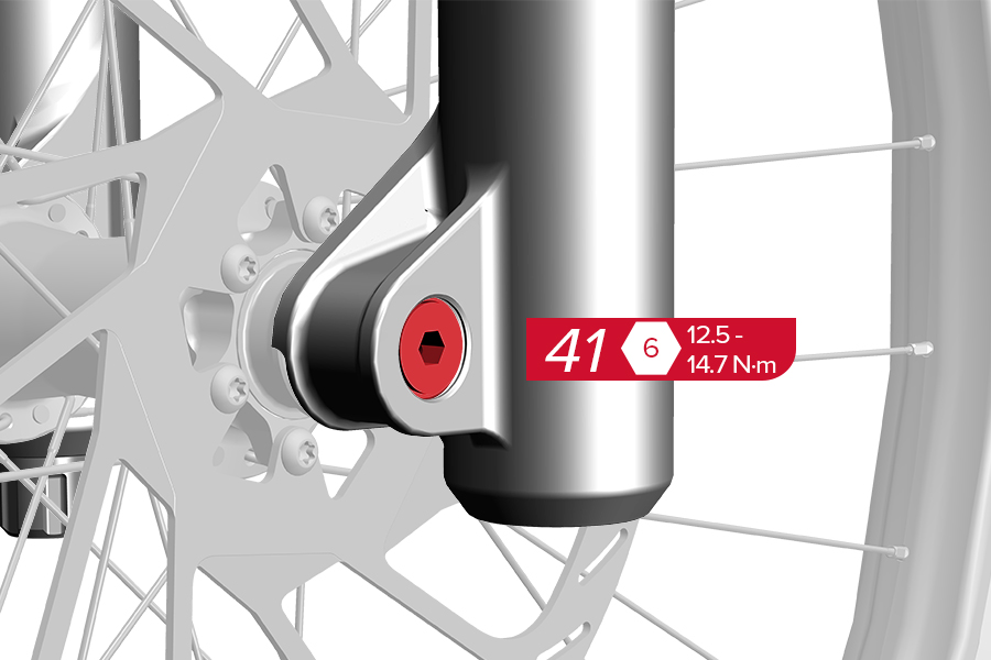
41. Tighten the Maxle DH (non-drive side).
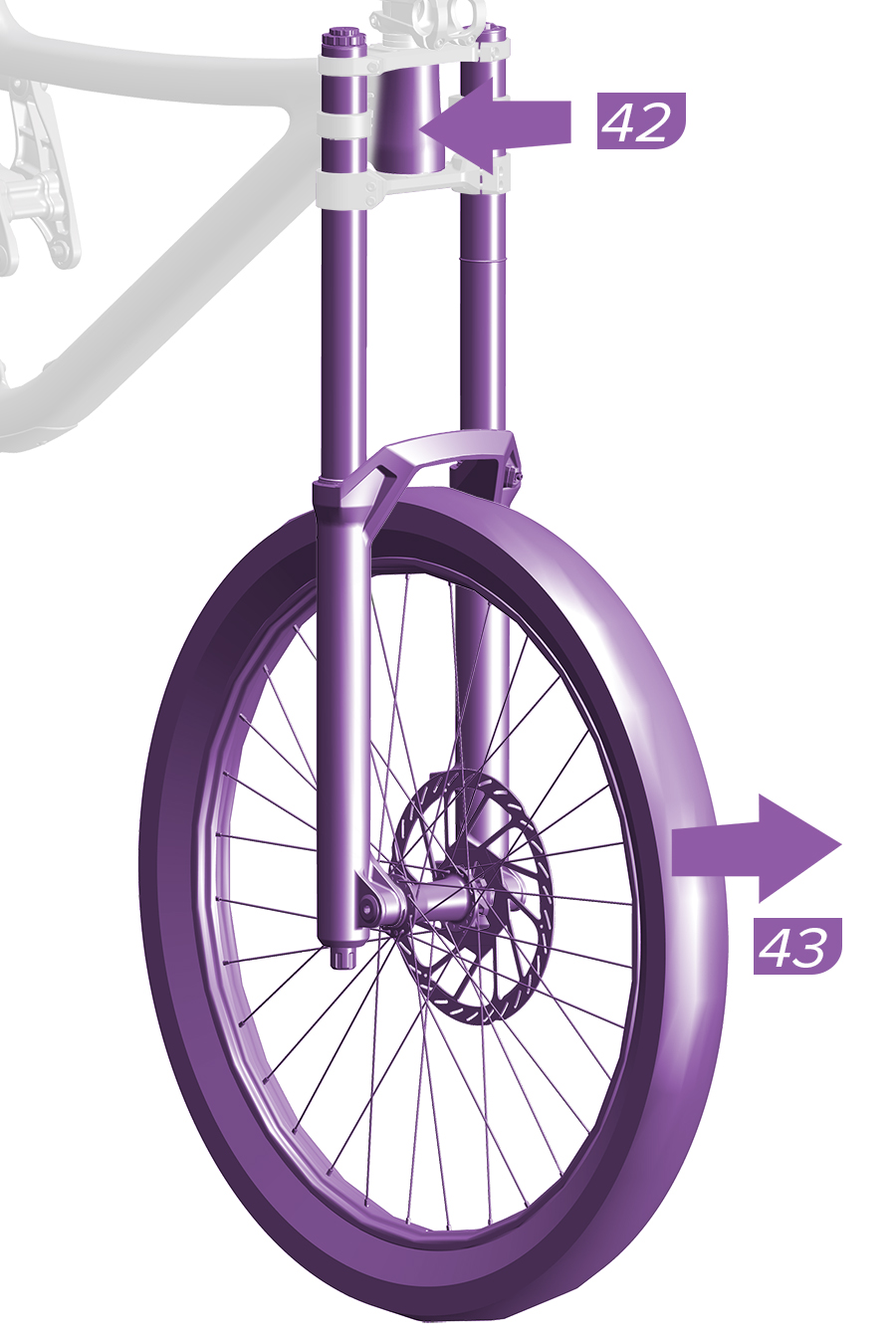
42. With the fork centered, grip the frame head tube with one hand, and the front wheel with other hand.
43. Quickly and firmly, pull the front wheel forward while applying opposing pressure to the headtube to properly align the upper tubes squarely and evenly in the crowns. Do not remove the wheel.
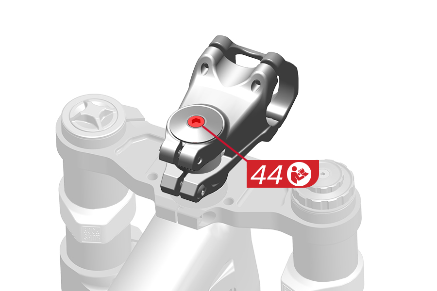
44. Tighten the headset top cap bolt according the headset manufacturer's instructions.
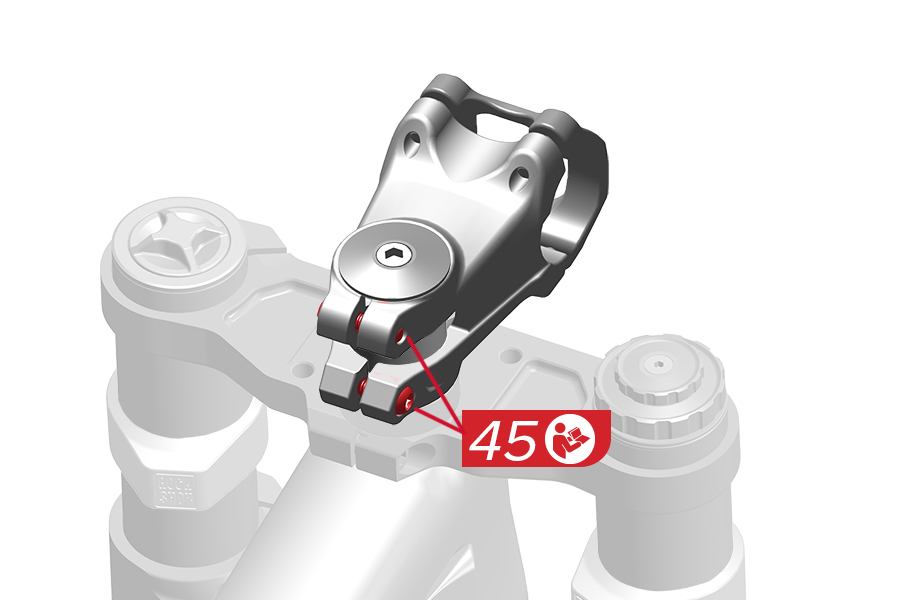
45. Tighten the stem bolt according to the stem manufacturer's instructions.
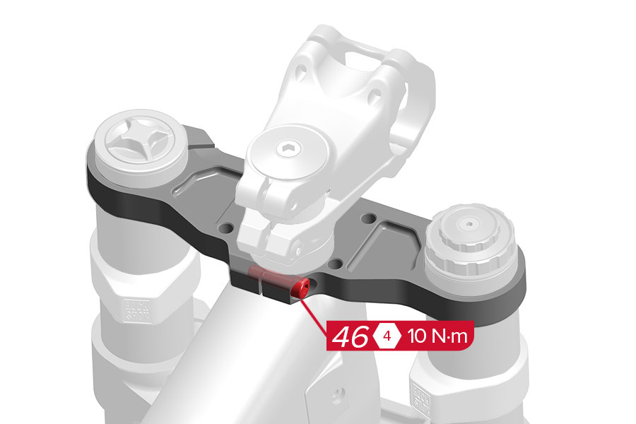
46. Tighten the upper crown steerer tube clamp bolt.
Do not tighten the upper crown steerer tube clamp bolt before the headset top cap is installed.
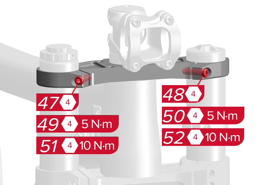
Tighten the upper crown bolts.
47. Tighten the damper side bolt finger tight. 48. Tighten the spring side bolt finger tight.
49. Tighten the damper side bolt to 5 N·m. 50. Tighten the spring side bolt to 5 N·m.
51. Tighten the damper side bolt to 10 N·m. 52. Tighten the spring side bolt to 10 N·m.
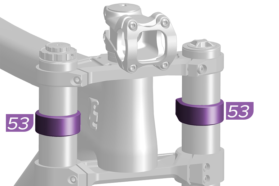
53. Adjust the position of each frame bumper as needed.
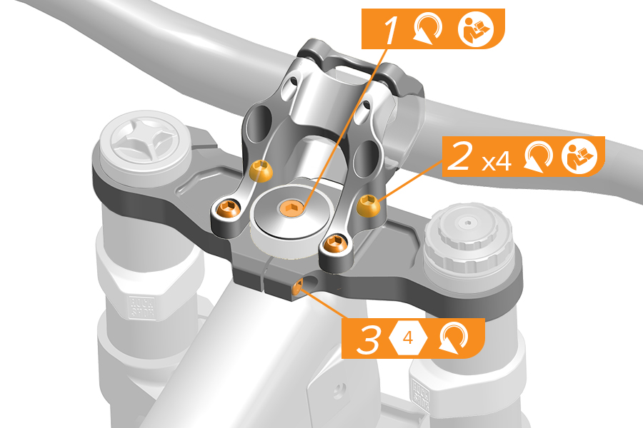
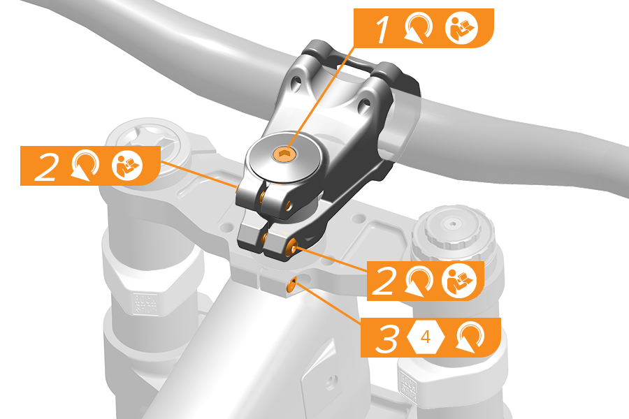
Fork height, or position within the upper and lower crowns, can be adjusted to optimize handlebar height and fork angle.
1. Loosen the steerer tube top cap bolt.
2. Loosen the stem bolt(s).
3. Loosen the upper crown steerer tube bolt.
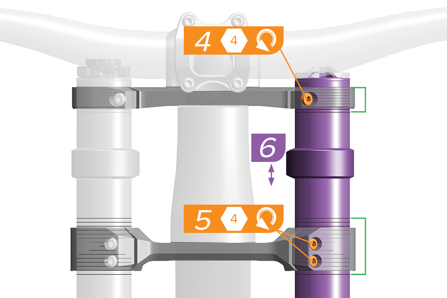
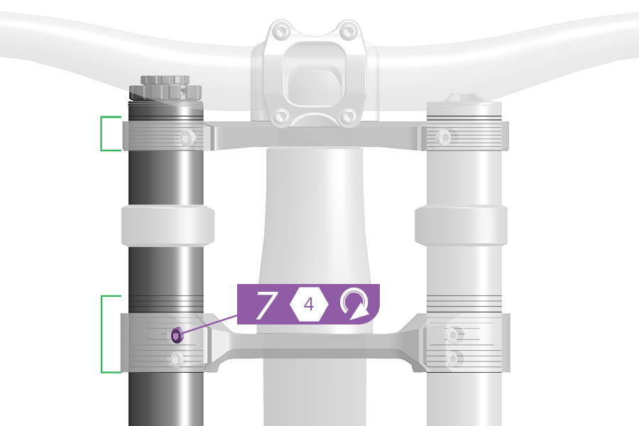
4. Loosen the spring side upper crown bolt.
5. Loosen the spring side lower crown bolts.
6. Adjust the spring side upper tube up or down.
7. Tighten one spring side lower crown bolt snug to hold the spring side upper tube in place.
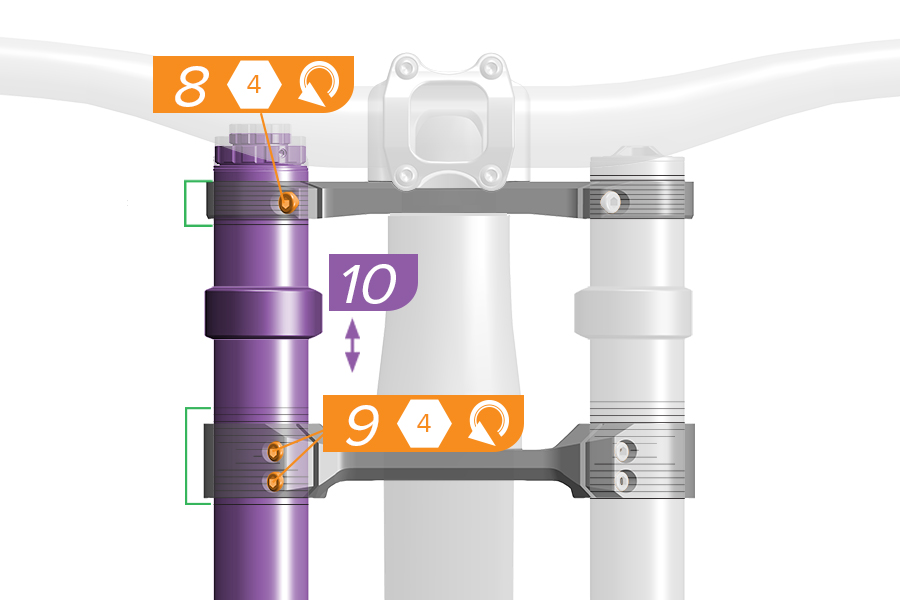
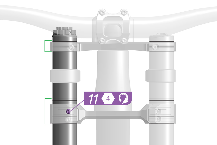
8. Loosen the damper side upper crown bolt.
9. Loosen the damper side lower crown bolts.
10. Adjust the damper side upper tube up or down, evenly with the spring side upper tube.
11. Tighten one damper side lower crown bolt snug to hold the upper tube in place.
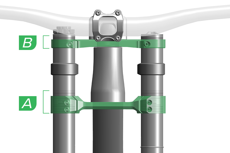
A. The lower crown must be even on both upper tubes and within the lower crown height gradients.
B. The bottom edge of the upper crown should be at or above the lowest gradient line on the upper tube, and the top edge of the upper crown should be at or below the top edge of the upper tube.
A. Do not position any part of the lower crown outside the lower crown height gradients. B. Do not position any part of the upper crown below the lowest crown height gradient on the upper tube, or above the top edge of each upper tube.
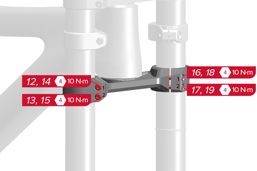
12-15. Damper Side: Tighten the lower crown bolts, top bolt first, lower bolt second. Repeat this sequence once more.
16-19. Spring Side: Tighten the lower crown bolts, top bolt first, lower bolt second. Repeat this sequence once more.
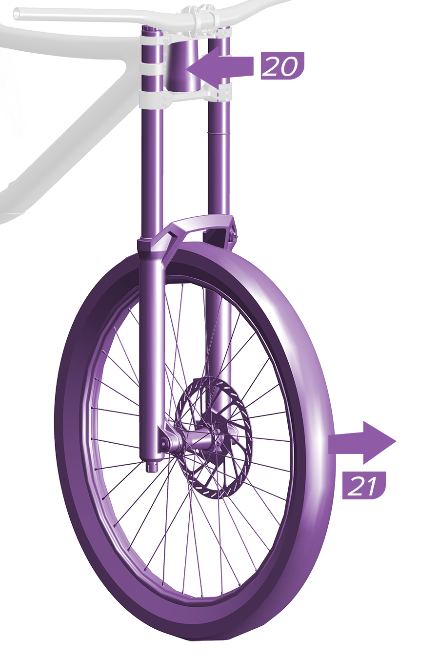
20. With the fork centered, grip the frame head tube with one hand, and the front wheel with other hand.
21. Quickly and firmly, pull the front wheel forward while applying opposing pressure to the headtube to properly align the upper tubes squarely and evenly in the crowns.
Do not remove the wheel.
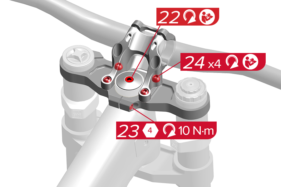
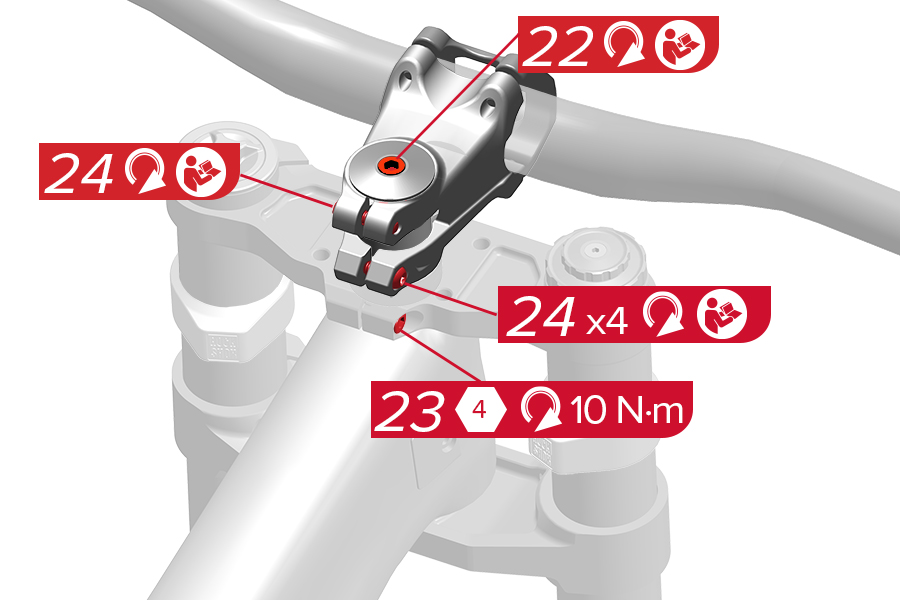
22. Tighten the steerer tube top cap bolt to the manufacturer's specified torque.
23. Tighten the upper crown steerer tube bolt to the specified torque.
24. Tighten the stem bolt(s) to the manufacturer's specified torque.
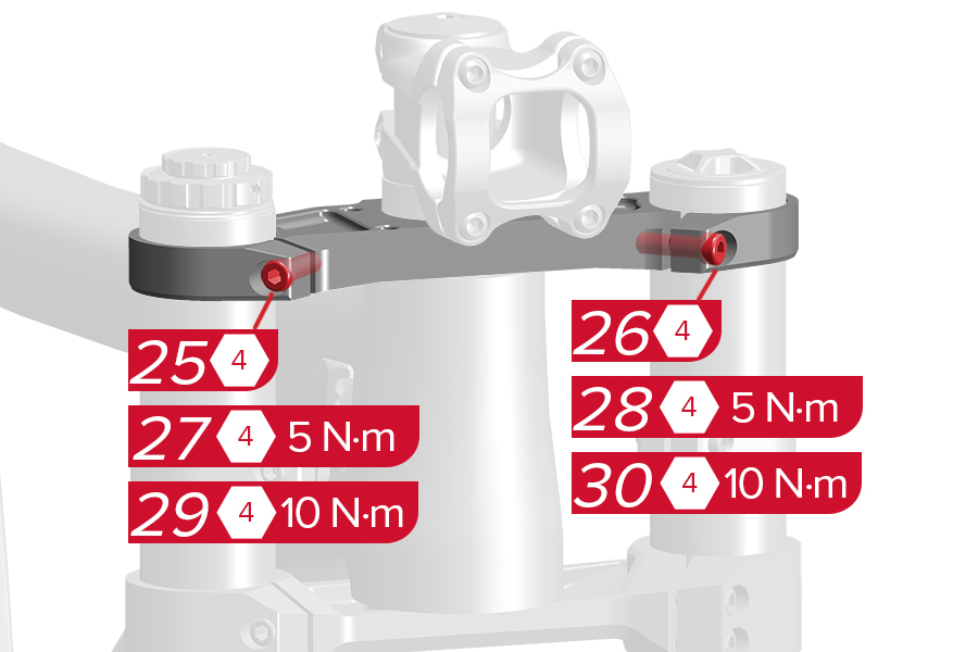
Tighten the upper crown bolts.
25. Tighten the damper side bolt finger tight. 26. Tighten the spring side bolt finger tight.
27. Tighten the damper side bolt to 5 N·m. 28. Tighten the spring side bolt to 5 N·m.
29. Tighten the damper side bolt to 10 N·m. 30. Tighten the spring side bolt to 10 N·m.
Install a disc brake caliper onto the suspension fork according to your brake manufacturer’s instructions.
CRASH HAZARD
Torque: Parts must be tightened to the specified torque. Failure to do so can result in SERIOUS INJURY OR DEATH.
Cables/Housing/Brake Hose: Do not allow cables, housing, or brake hose to rest on or be attached to the fork crown, steerer tube, or upper tubes. Contact and abrasion over time could result in damage to components, loss of control, and possible SERIOUS INJURY OR DEATH. Damage from abrasion is not covered under warranty.
Brake Hose/Housing: Secure the brake hose or housing in the fork cable guide, or to the fork lower leg with a cable tie. Failure to secure the brake hose or housing could affect braking which could result in SERIOUS INJURY OR DEATH. Compress the fork to full bottom out and confirm the hose or housing does not contact the tire. Contact can damage the brake hose or housing and could affect braking which could result in SERIOUS INJURY OR DEATH.
Internal Routing: Confirm internally routed cables, housing or brake hoses do not contact the steerer tube. Any contact may cause abrasions, which over time can cause damage which may result in loss of control, leading to SERIOUS INJURY OR DEATH. Inspect the steerer tube during service intervals to ensure the steerer tube is not worn or damaged. If damaged, replace the crown steerer upper tube prior to riding to avoid SERIOUS INJURY OR DEATH. If resistance is felt while steering, stop riding and confirm the cables, housing, and brake hoses are not making contact with the steerer tube. Eliminate contact prior to riding to avoid SERIOUS INJURY OR DEATH.
To avoid permanent damage to the fork lower leg, do not exceed the maximum torque specification for the fork's threaded mounting points.
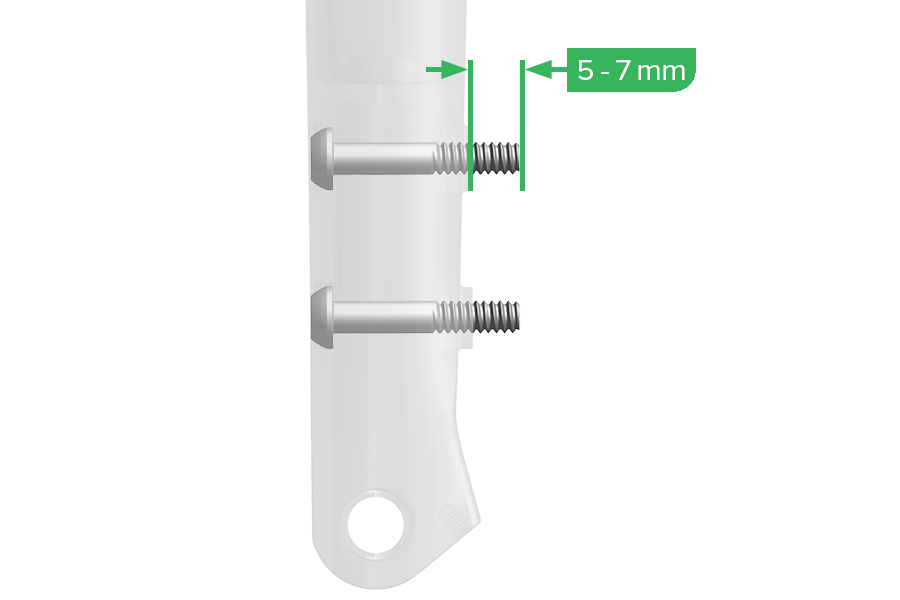
There must be 9-13 mm of mounting bolt thread engagement when mounting brake calipers to forks and frames either with or without brackets and/or spacers. Riding a bike with improper bolt engagement can allow the brakes to disengage from the bicycle, which can lead to a crash and serious injury or death to the rider.
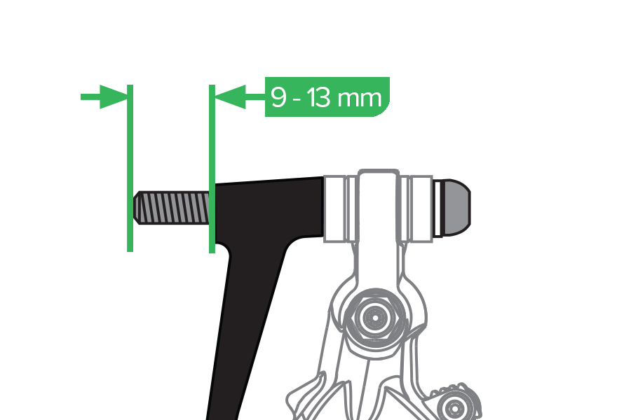
Rudy XPLR: There must be 5-7 mm of mounting bolt thread engagement when mounting the brake caliper to the fork. Riding a bike with improper bolt engagement can allow the brakes to disengage from the bicycle, which can lead to a crash and serious injury or death to the rider.
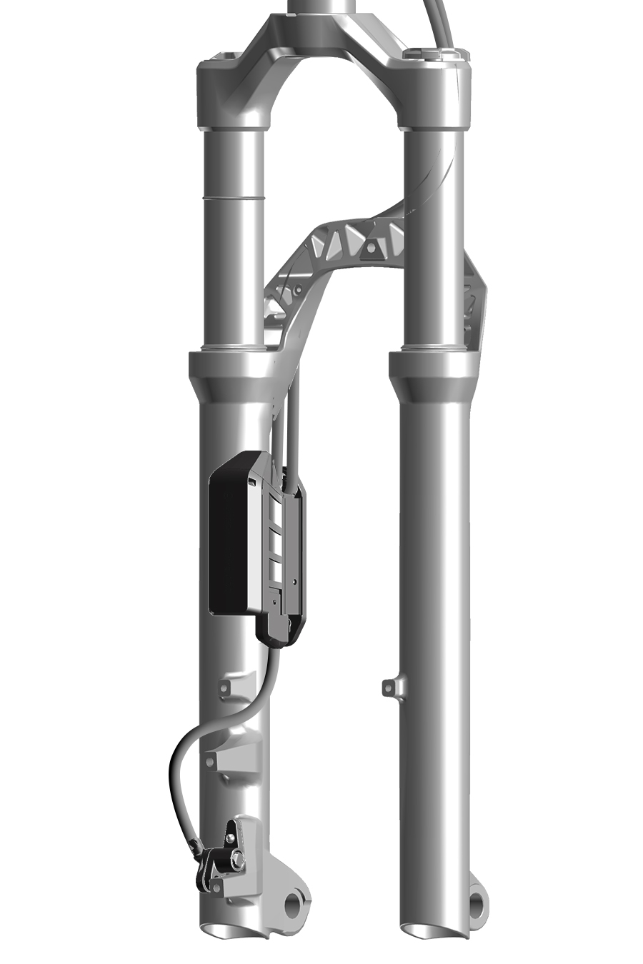
CRASH HAZARD: To avoid ABS malfunction, install all ABS components according to the manufacturer's instructions.
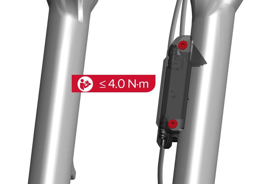
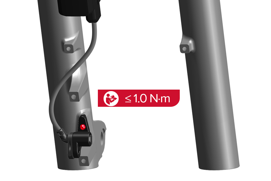
Install ABS components according to the manufacturer's instructions. Tighten the bolts to the manufacturer's specified torque, but do not exceed the maximum torque specification for the fork's mounting points.
ABS components can only be installed onto an ABS-compatible RockShox fork.
To avoid permanent damage to the fork lower leg, do not exceed the maximum torque specification for the fork's threaded mounting points.
CRASH HAZARD: Secure the ABS component wires to the fork lower leg as instructed by the manufacturer. Failure to secure wires could affect function and braking which could result in SERIOUS INJURY OR DEATH. Compress the fork to full bottom out and confirm the wires do not contact the tire, the disc brake caliper, or the disc brake rotor. Contact can damage the wire which can affect function and braking, and could result in SERIOUS INJURY OR DEATH.
Some RockShox suspension forks feature an integrated brake hose/housing guide. Secure the disc brake hose or housing into the suspension fork hose/housing guide. If your fork does not include a brake hose/housing guide, secure the brake hose or housing to the fork arch with a cable tie.
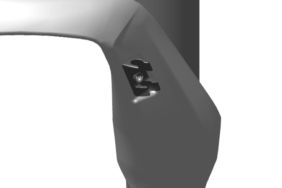
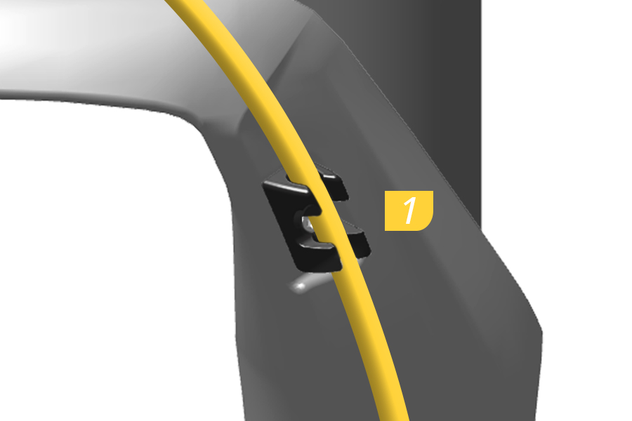
1. Press the brake hose or housing into the press-fit hose/housing guide. Secure the brake hose or housing with a cable tie additionally as needed.
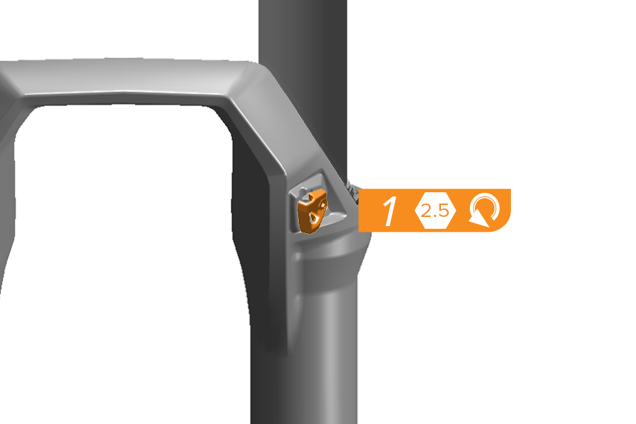
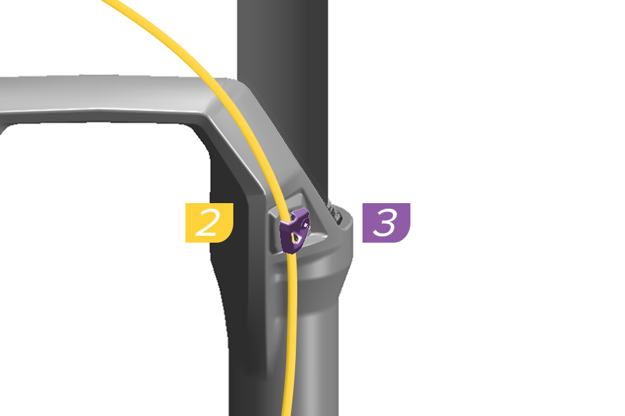
1. Loosen the hose/housing clamp bolt.
2. Separate the hose/housing clamp plate away from the lower leg.
3. Install the brake hose/housing onto the lower leg under the clamp plate.
4. Install the guide plate onto the lower leg over the brake hose/housing.
5. Hold the clamp plate in place and tighten the bolt snug/finger tight.
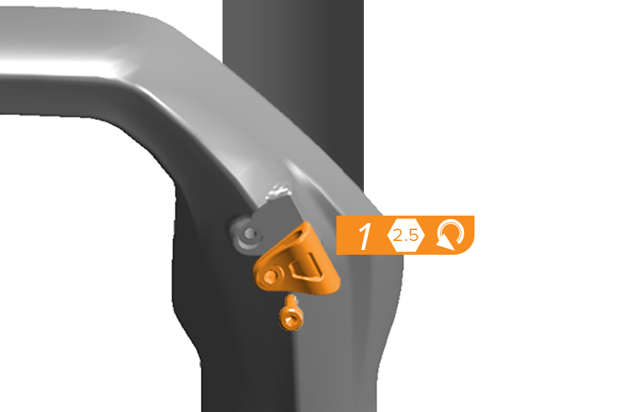
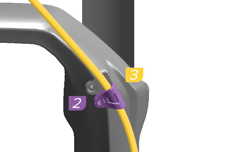
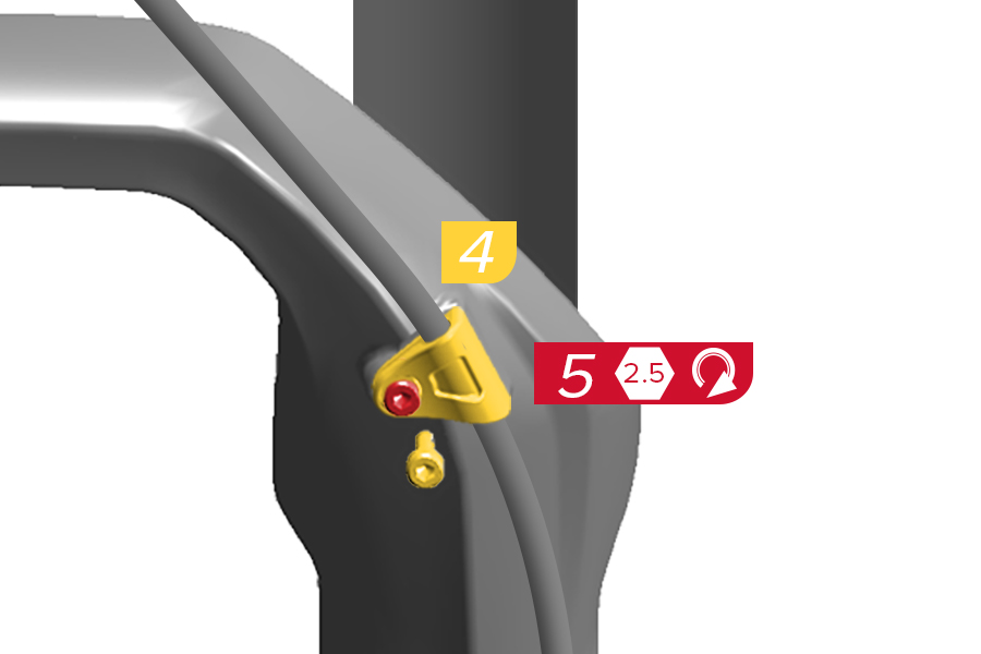
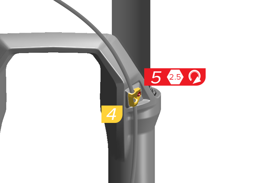
1. Remove the clamp bolt and brake hose/housing clamp.
2. Open the clamp.
3. Install the brake hose/housing into the clamp.
4. Install the clamp flat onto the lower leg and thread the bolt into the lower leg.
5. Tighten the brake hose/housing clamp bolt snug/finger tight.
Some RockShox front suspension forks include end cap adapters that can be installed if a front standard thru axle hub does not include RockShox Torque Caps. End cap adapters assist with front hub/wheel installation.
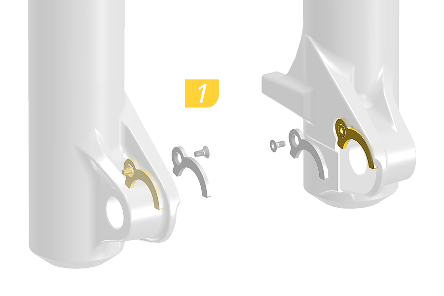
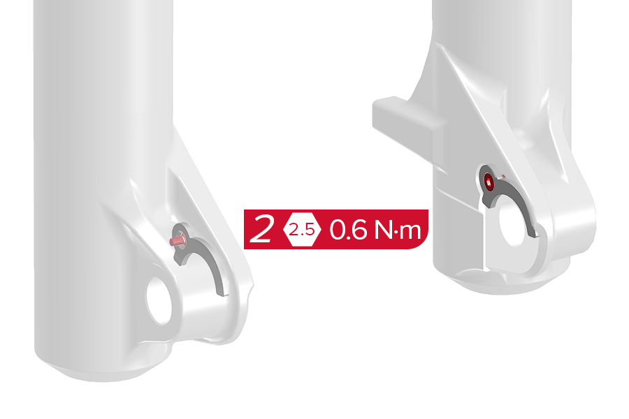
1. Install hub end cap adapters if a hub without Torque Cap end caps is installed into the fork.
2. Tighten each bolt to the specified torque.
CRASH HAZARD:
Installation: The Maxle system allows the use of a thru axle hub for enhanced stiffness. The axle threads into the dropout and compresses the hub. The axle is fixed into place by applying the required torque indicated. Never use any tool other than what is indicated to tighten the axle into the dropouts. Under-tightening or over-tightening of the axle can damage the axle, dropouts, and/or the hub.
Torque: Parts must be tightened to the specified torque. Failure to do so can result in SERIOUS INJURY OR DEATH.
Wheel Installation: Riding with an improperly installed wheel can allow the wheel to move or disengage from the bicycle, causing damage to the bicycle, and serious injury or death to the rider. It is essential that you:
■ Ensure that your axle, dropouts, and quick release mechanisms are clean and free of dirt or debris.
■ Ask your dealer to help you understand how to properly secure your wheel using the Maxle thru axle.
■ Apply the correct techniques when installing your wheels.
Clearance: Tire: Failure to leave at least 6 mm clearance between the top of the inflated tire and the bottom of the crown will cause the tire to jam against the crown when the fork is fully compressed, which can result in SERIOUS INJURY OR DEATH. Fender: Failure to leave at least 6 mm clearance from the fender stay and the tire sidewall, and 6 mm between the fender stay and the disc brake caliper, can result in SERIOUS INJURY OR DEATH.
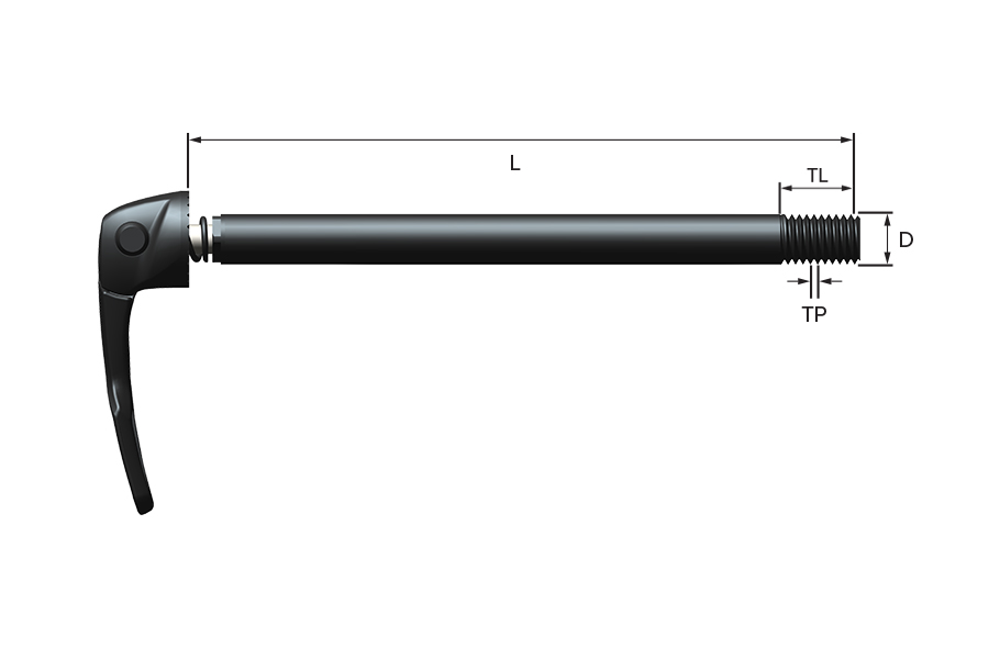
D = Diameter
L = Axle Length
TL = Thread Length
TP = Thread Pitch
Maxle is available in a variety of specifications for both MTB and Road. Consult your frame or fork manufacturer for compatibility. Refer to the (RockShox) Spare Parts Catalog for additional information and availability.
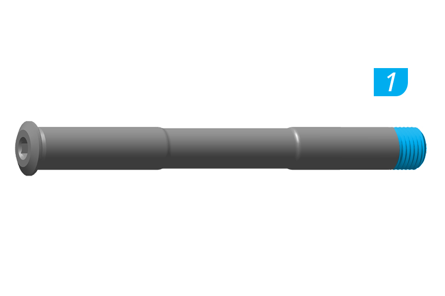
1. Apply grease to the axle threads.
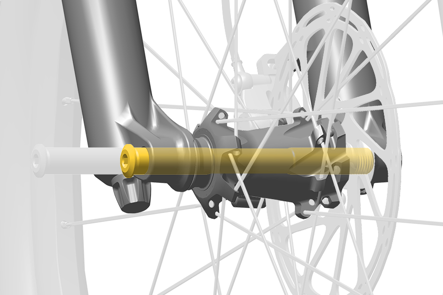
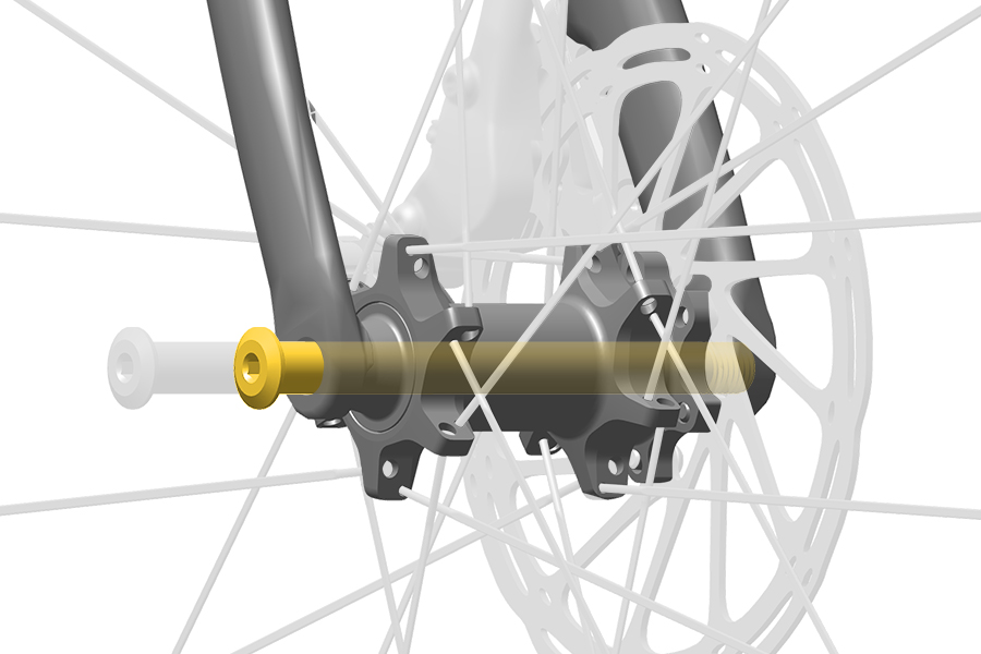
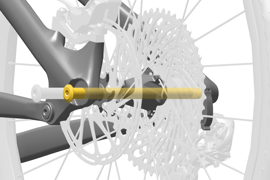
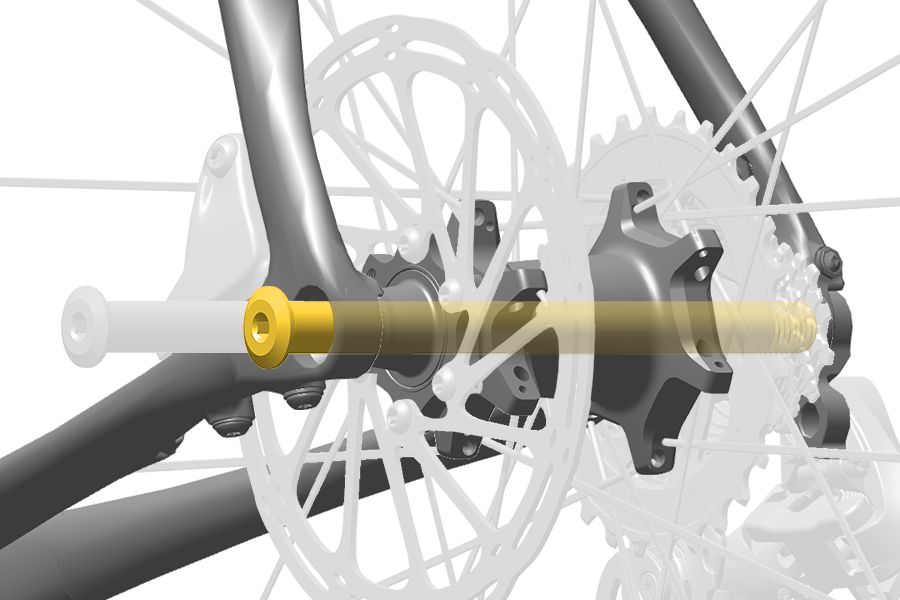
2. Slide the Maxle through the drop out and hub until it contacts the threads of the opposite side drop out.
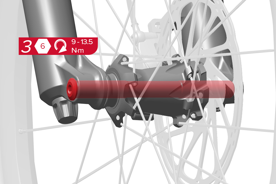
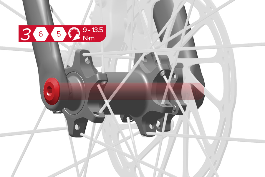
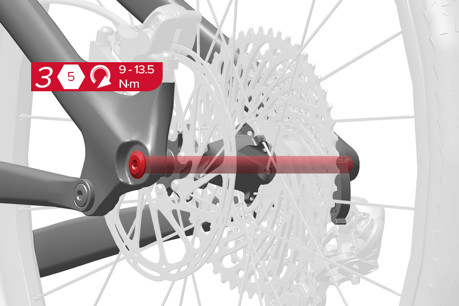
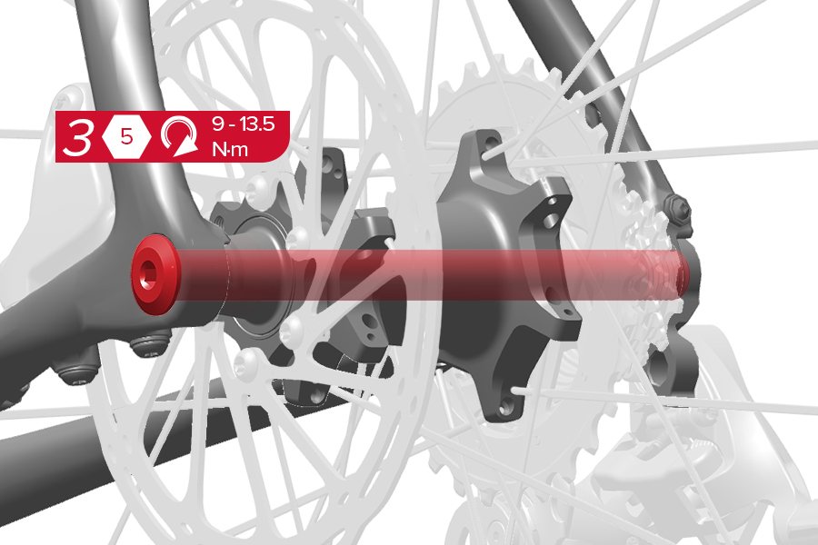
3. Tighten the Maxle to the specified torque.
The Maxle lever must not contact the fork or frame in the closed position. Contact may result in insufficient lever tension.
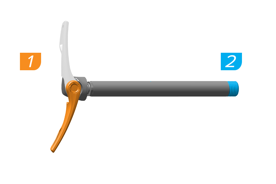
1. Open the Maxle lever. Ensure the lever rests against the hard stop.
2. Apply grease to the axle threads.
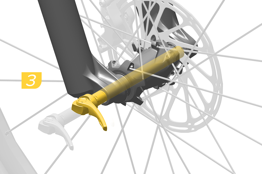
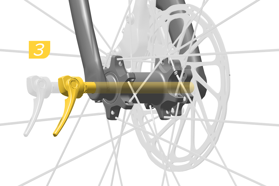
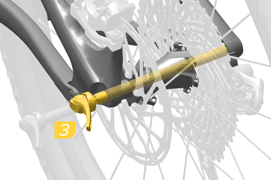
3. Slide the Maxle through the drop out and hub until it contacts the threads of the opposite side drop out.
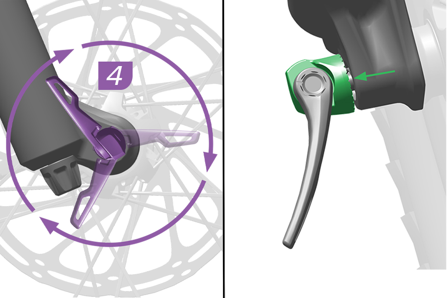
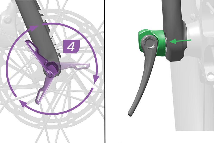
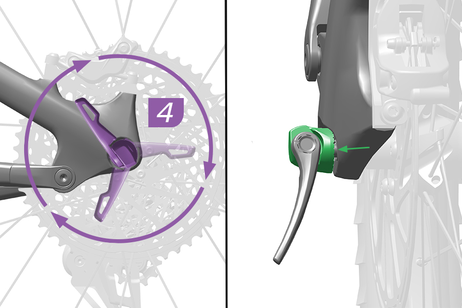
4. To thread the Maxle into the drop out, rotate the lever clockwise until there is a small gap between the lever head and drop out.
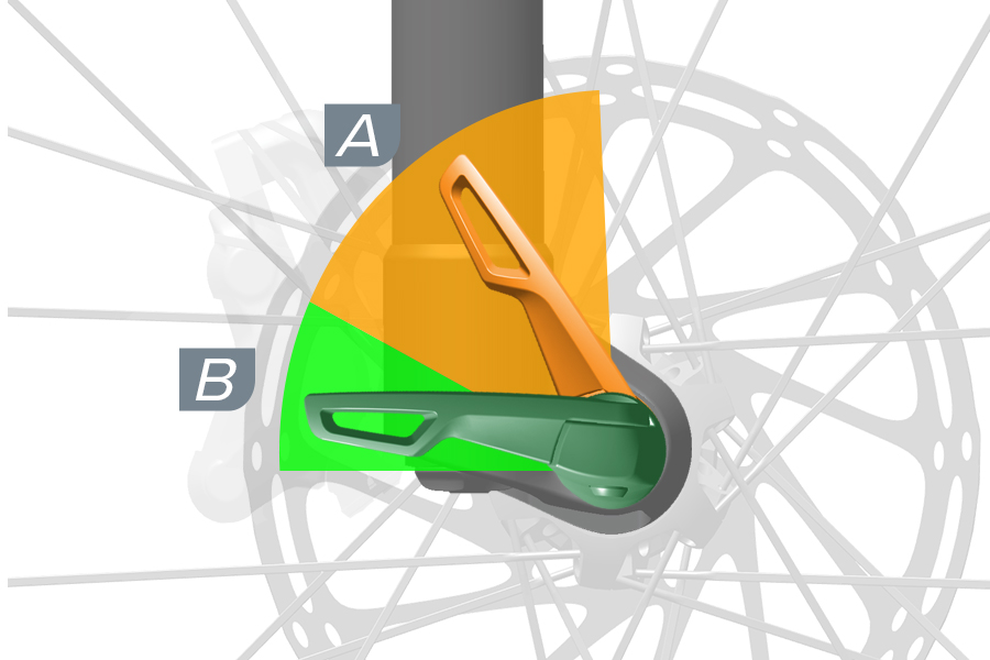
CRASH HAZARD: RS-1: The Maxle lever must not be in the (A) orange shaded area when tightened. To tighten the Maxle correctly, close the Maxle lever ONLY in the (B) green shaded area.
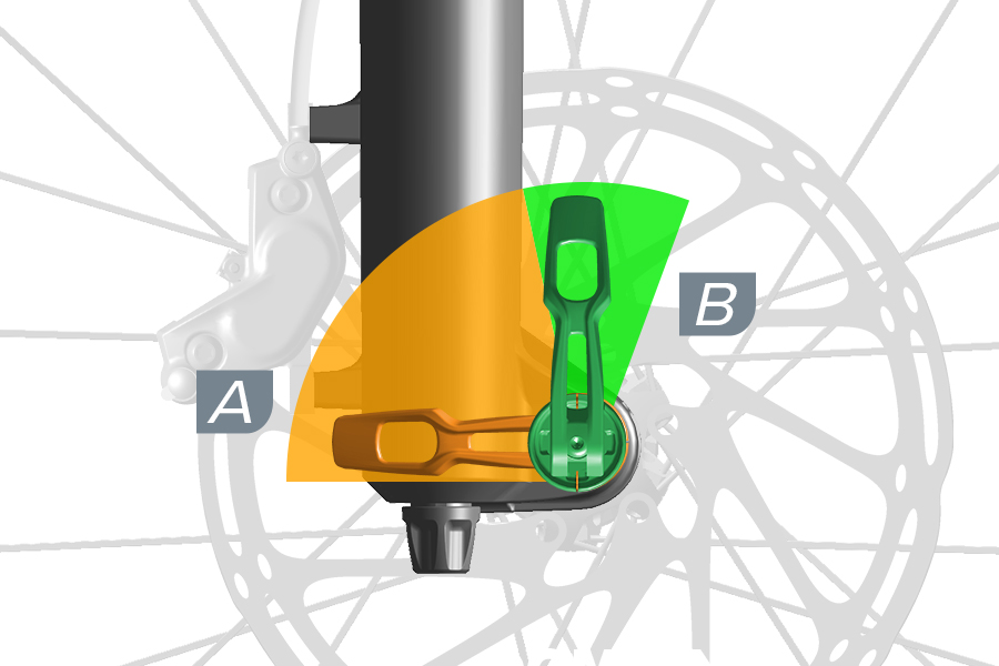
Forks with 38 mm upper tubes: The Maxle lever cannot be closed in the (A) orange shaded area. To tighten the Maxle correctly, close the Maxle lever ONLY in the (B) green shaded area.
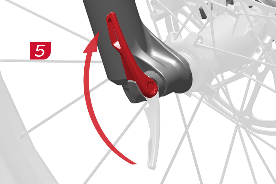
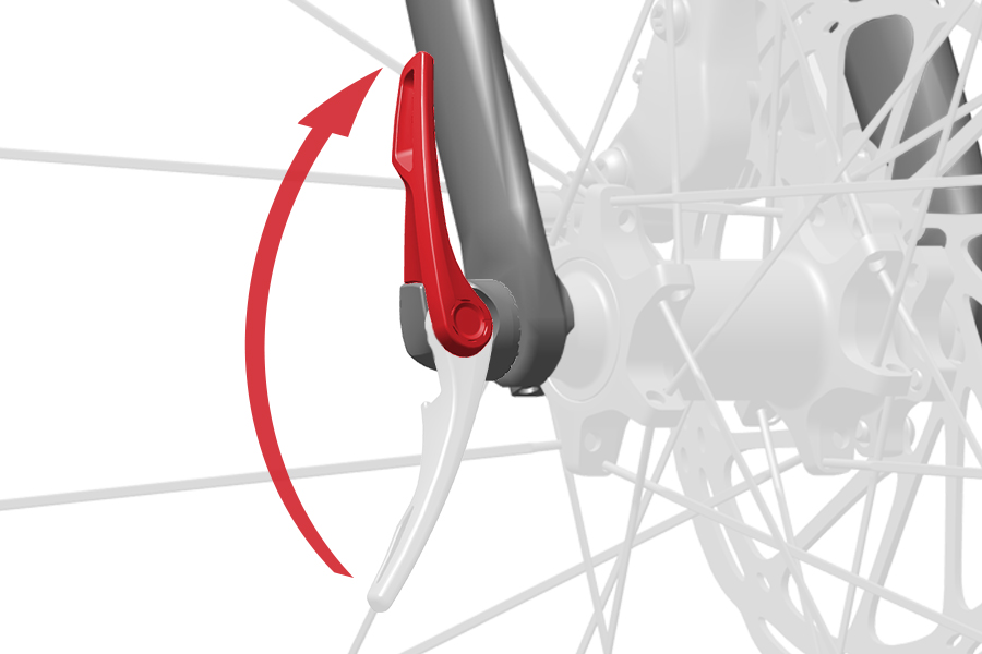
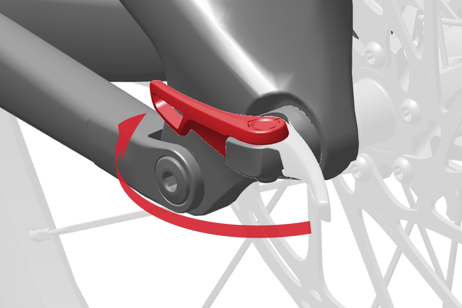
5. Close the lever and confirm it does not contact the fork or frame. Lever tension is sufficient if the lever leaves an imprint on your hand.
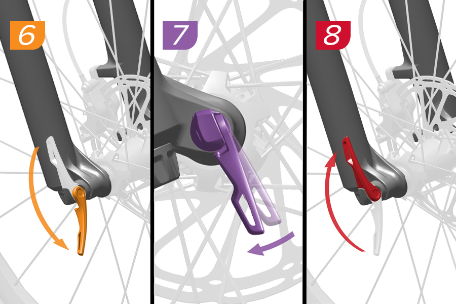
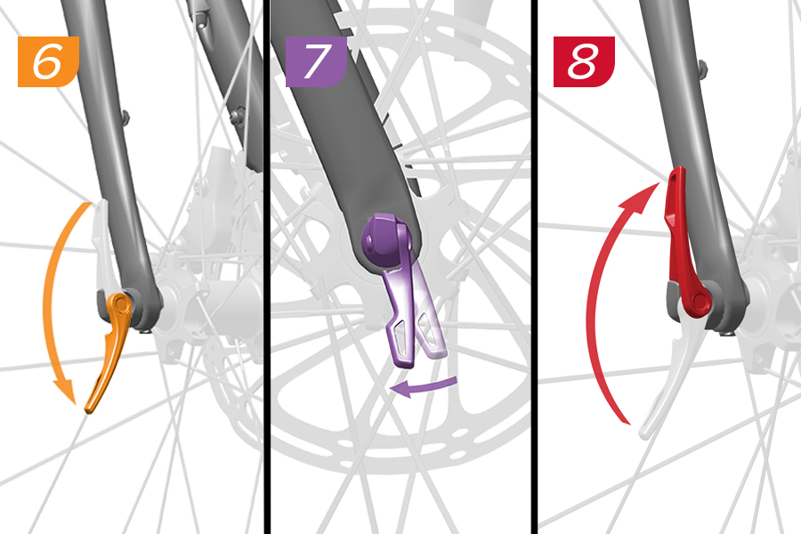
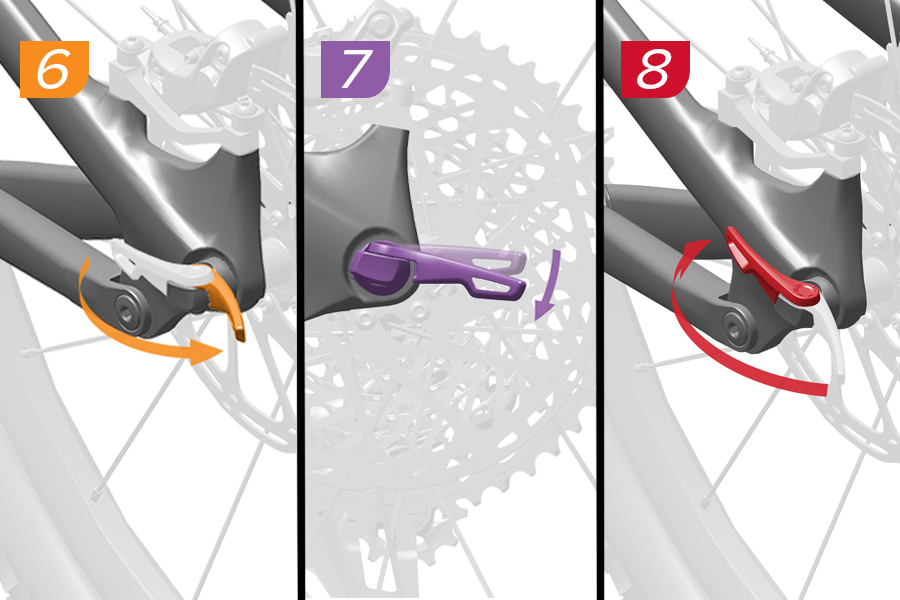
6-7. To increase lever tension, open the lever and rotate it clockwise.
8. Close the lever to recheck lever tension. Repeat until the tension is sufficient, then close the lever. When the lever is closed, verify there is no gap between the lever head and dropout.
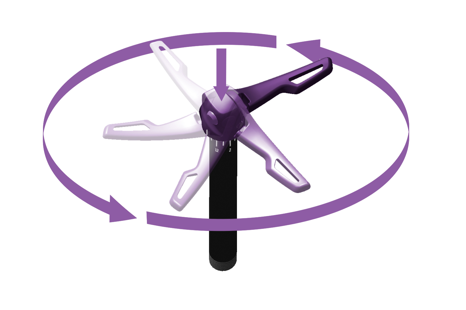
Remove the Maxle and adjust the lever position as needed. To change the closed position of the Maxle lever, open the lever, press down, and rotate the lever head to the desired position. Adjust the lever until it can be closed without contacting the fork or frame.
The Maxle lever must not contact the fork or frame in the closed position. Contact may result in insufficient lever tension.
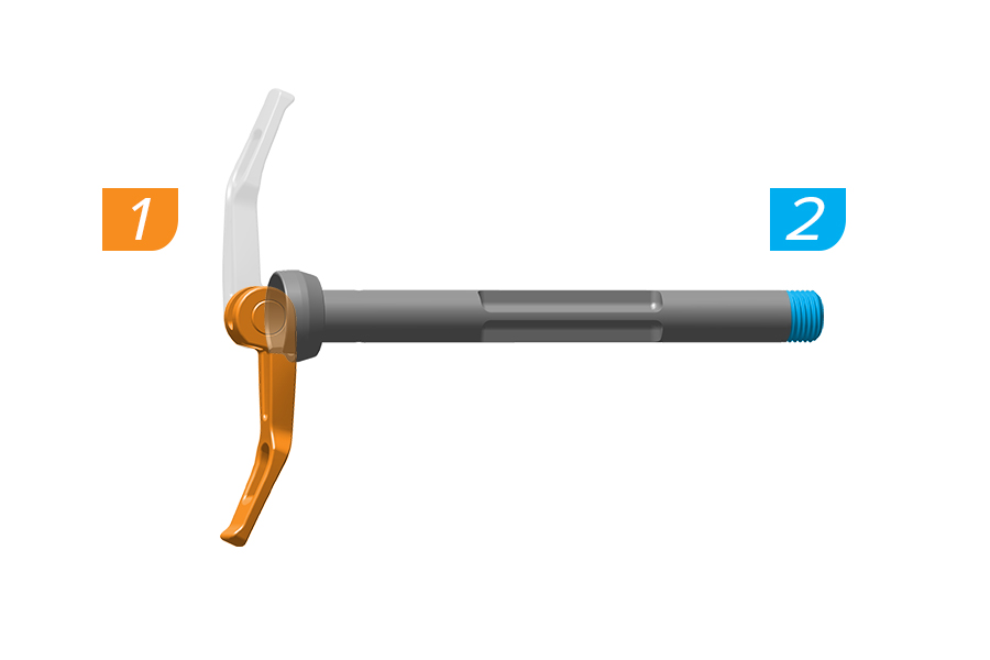
1. Open the Maxle lever. Ensure the lever rests in the notch on the axle flange.
2. Apply grease to the axle threads.
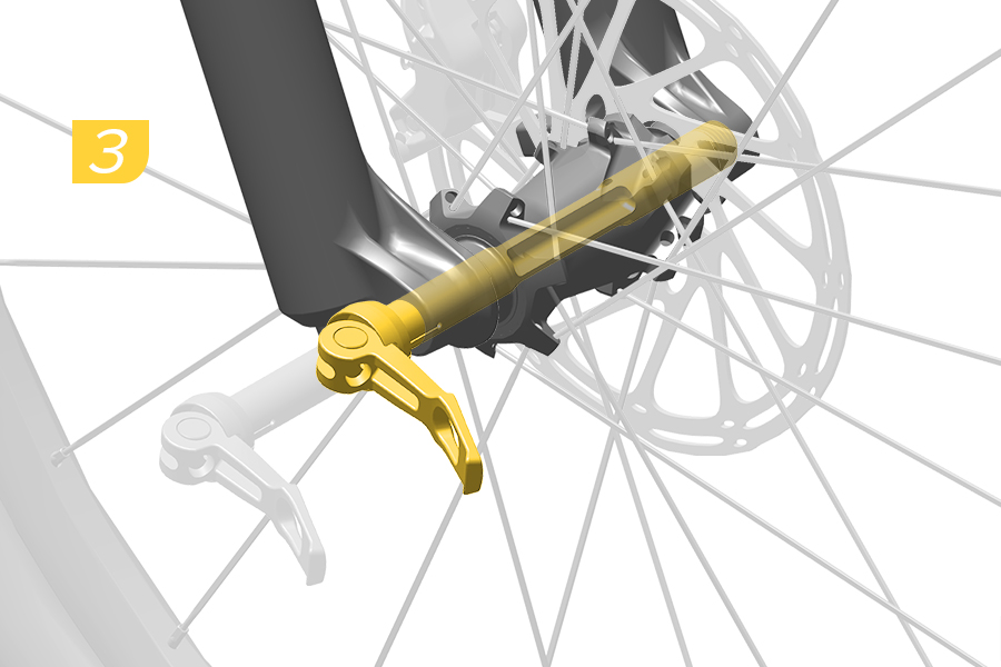
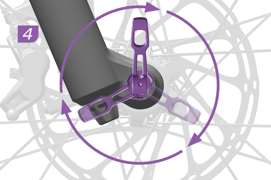
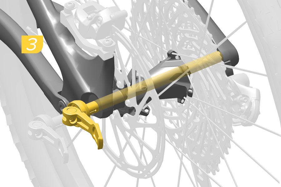
3. Slide the Maxle through the drop out and hub until it contacts the threads of the opposite side drop out.
4. To thread the Maxle into the drop out, rotate the lever clockwise until it stops.
.jpg)
Forks with 38 mm upper tubes: The Maxle lever cannot be closed in the (A) orange shaded area. To tighten the Maxle correctly, close the Maxle lever ONLY in the (B) green shaded area.
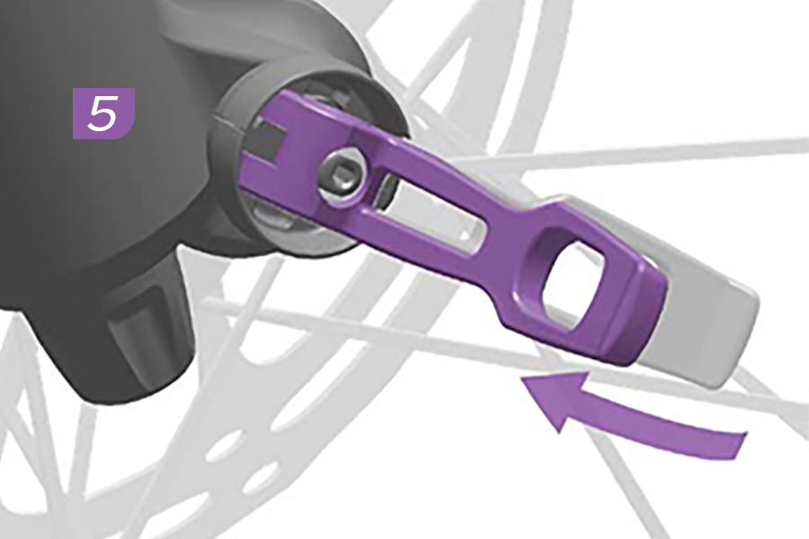
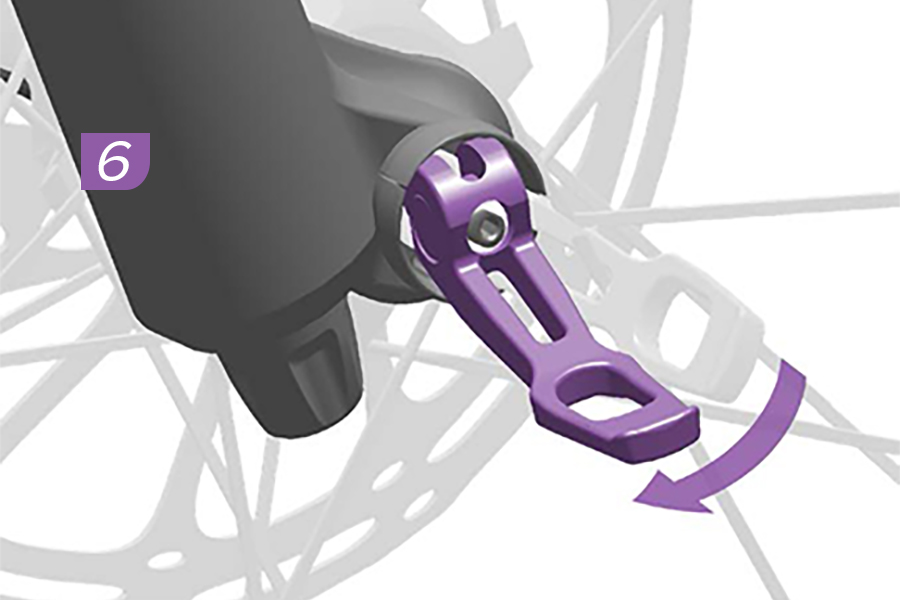
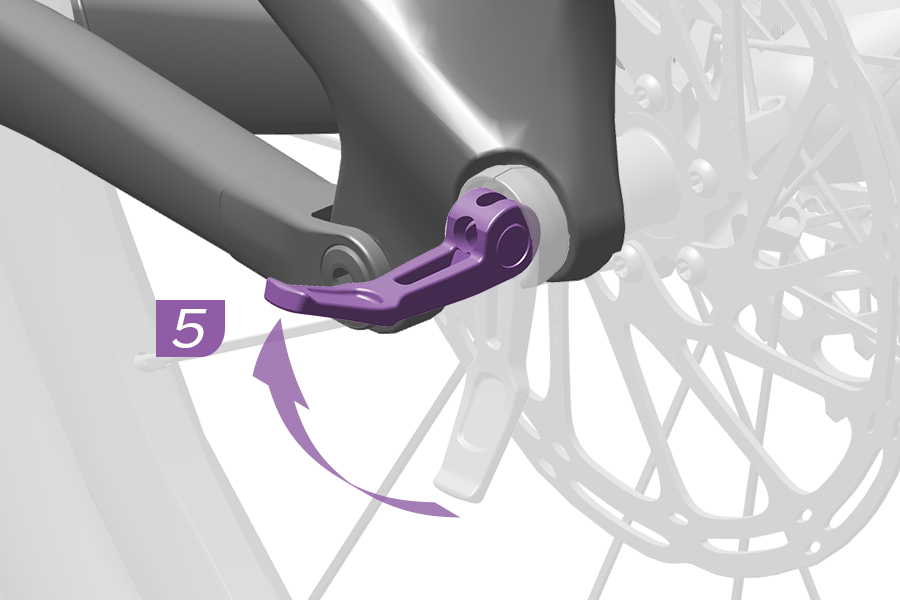
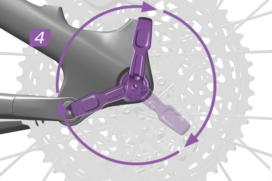
5. Disengage the Maxle lever from the notch in the axle flange.
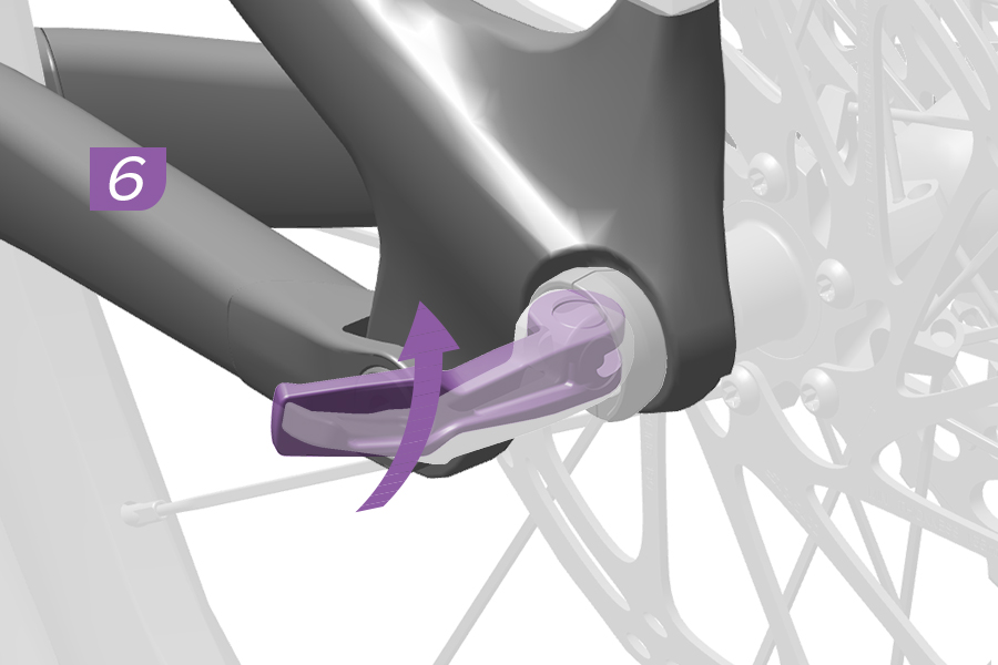
6. Rotate the lever to the intended closed position.
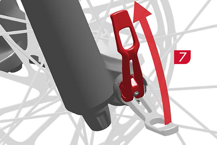
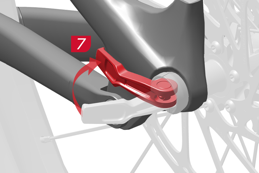
After closing the Maxle quick release lever, do not reposition or spin the lever. Repositioning or spinning the Maxle lever can cause the axle to come loose, compromising the security of the axle which can lead to serious injury and/or death.
7. Close the lever and confirm it does not contact the fork or frame. Lever tension is sufficient if the lever leaves an imprint on your hand.
INCREASE LEVER TENSION
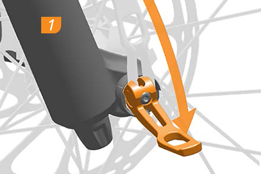
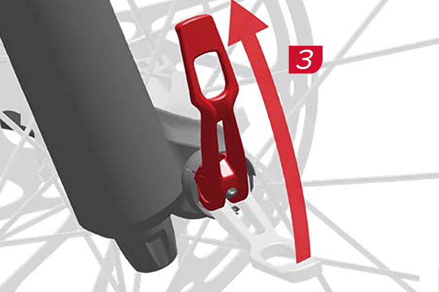
1. To increase lever tension, open the lever and position it in the notch.
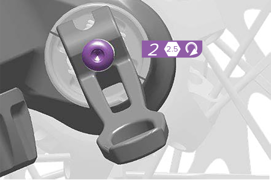
2. Use a 2.5 mm hex wrench to turn the tension adjuster clockwise one click.
3. Close the lever to recheck tension. Repeat until the tension is sufficient, then close the lever in the desired position.
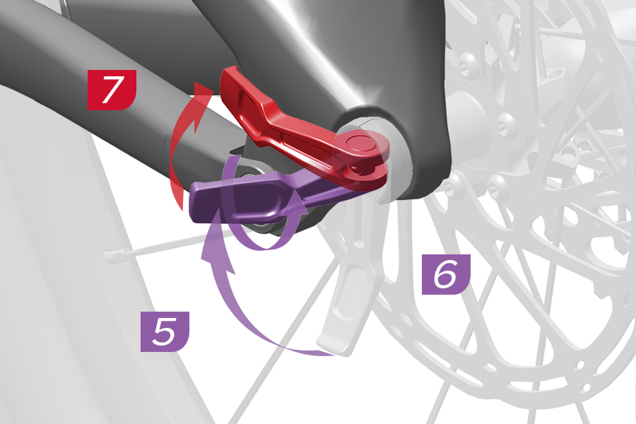
INCREASE LEVER TENSION
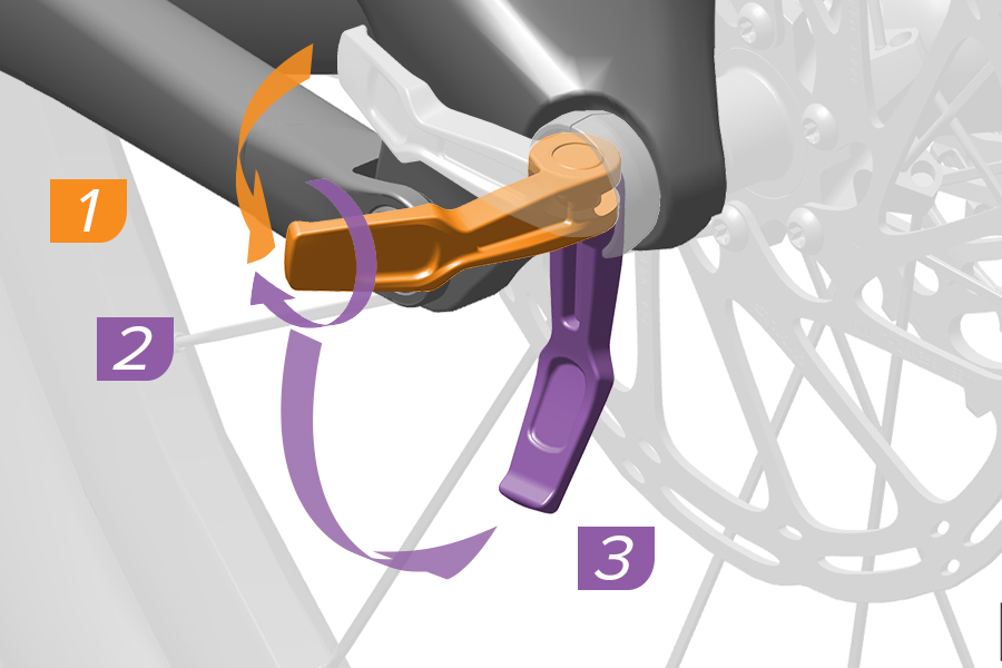
1-3. To increase lever tension, open the lever and position it in the notch.
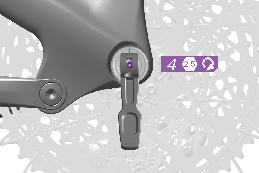
4. Use a 2.5 mm hex wrench to turn the tension adjuster clockwise one click.
5-7. Close the lever to recheck tension. Repeat until the tension is sufficient, then close the lever in the desired position.
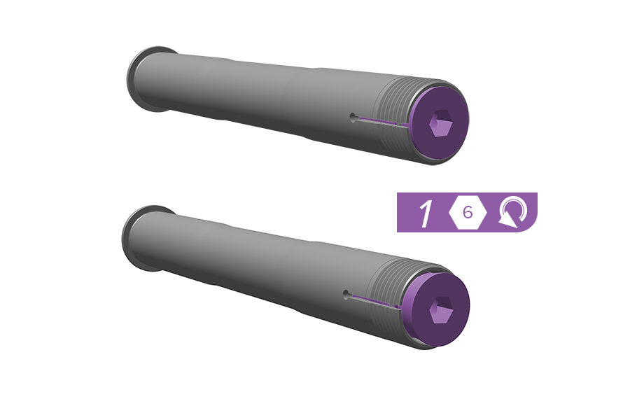
1. Turn the non-drive side wedge expander counter-clockwise three revolutions to loosen the expander.
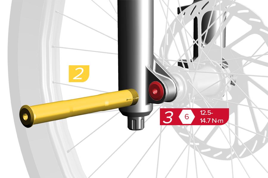
2. Install the Maxle DH through the drive side dropout.
3. Tighten the Maxle DH to the specified torque.
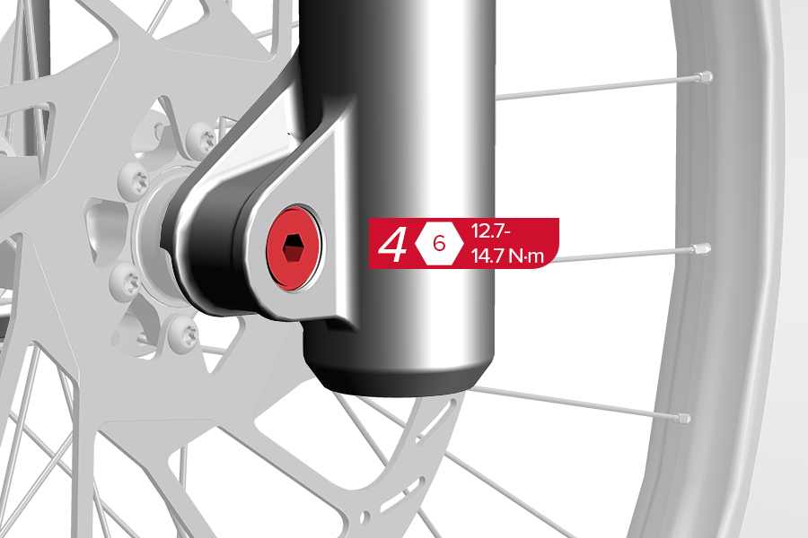
4. Tighten the non-drive side wedge expander to the specified torque.
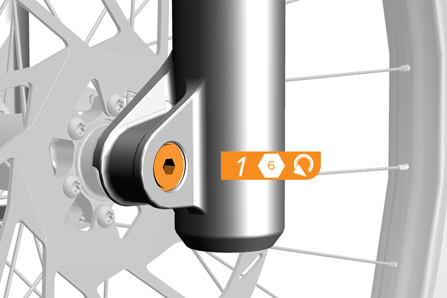
1. Turn the non-drive side wedge expander counter-clockwise three revolutions to loosen the expander.
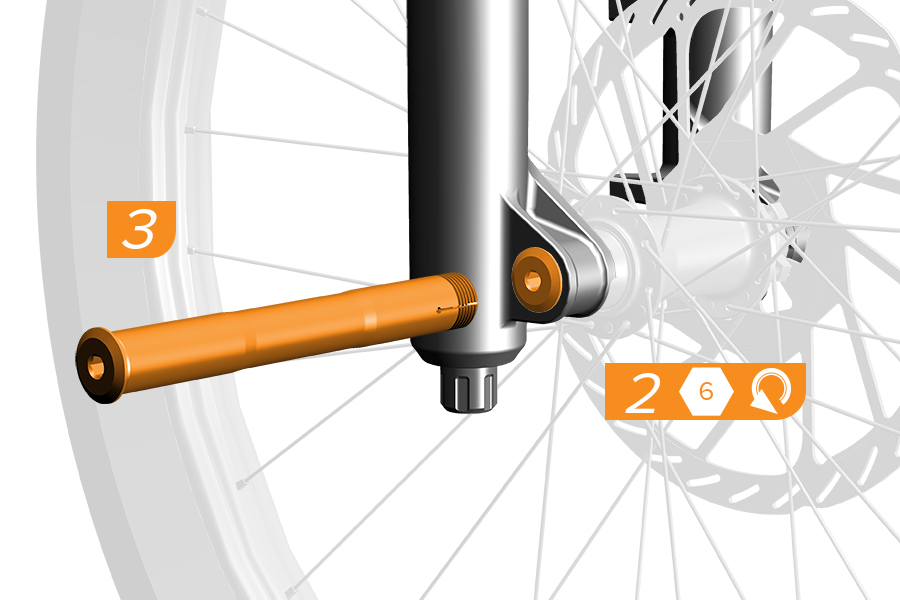
2. Unthread the Maxle DH from the drive side dropout.
3. Remove the Maxle DH from the fork.
Riding with an improperly installed wheel can allow the wheel to move or disengage from the bicycle, causing damage to the bicycle, and serious injury or death to the rider. It is essential that you:
■ Ensure that your axle, dropouts, and quick release mechanisms are clean and free of dirt or debris.
■ Ask your dealer to help you understand how to properly secure your wheel using the Maxle thru axle.
■ Apply the correct techniques when installing your wheels.
CRASH HAZARD: Tire: Failure to leave at least 6 mm clearance between the top of the inflated tire and the bottom of the crown will cause the tire to jam against the crown when the fork is fully compressed, which can result in SERIOUS INJURY OR DEATH. Fender: Failure to leave at least 6 mm clearance from the fender stay and the tire sidewall, and 6 mm between the fender stay and the disc brake caliper, can result in SERIOUS INJURY OR DEATH.
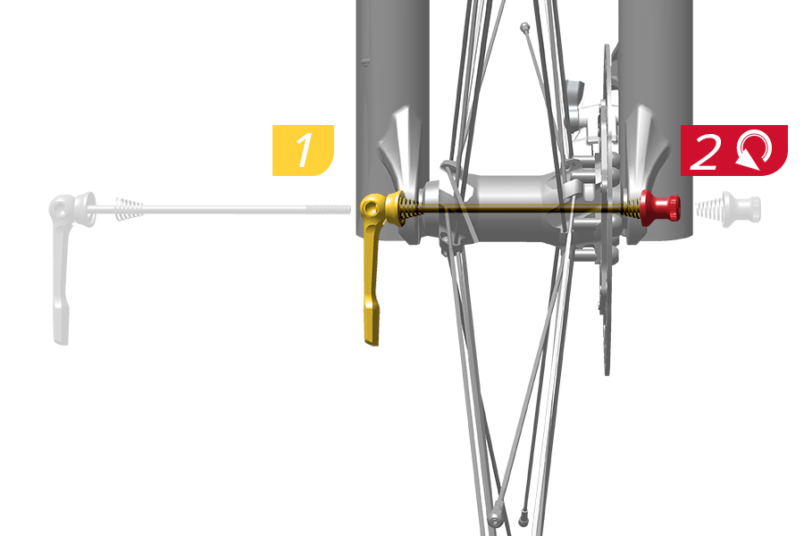
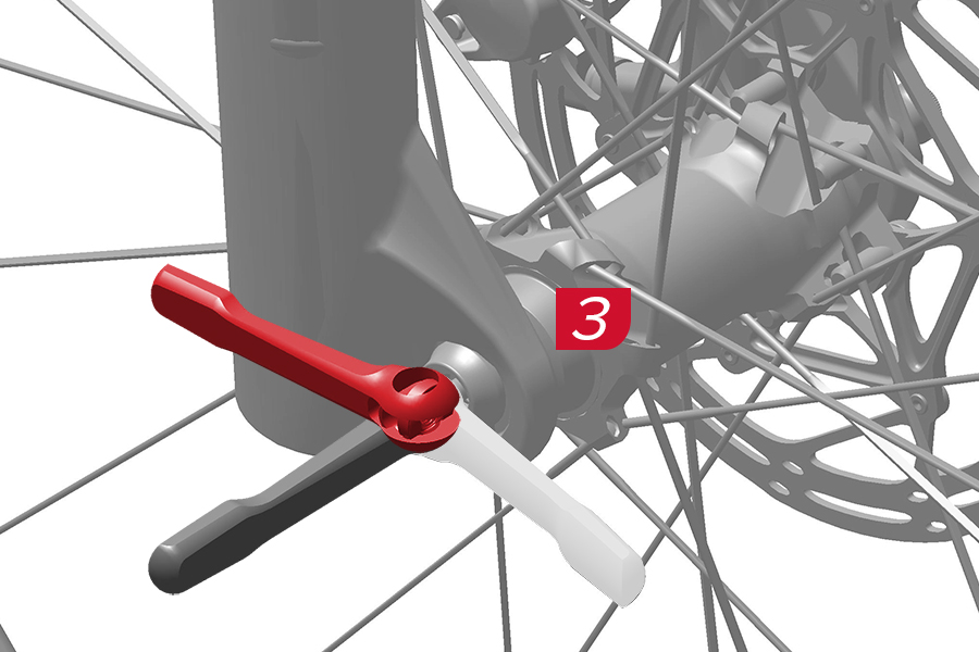
1-3. Install the front wheel onto the bicycle according to the wheel manufacturer's instructions. Lever tension is sufficient if the lever leaves an imprint on your hand and the adjusting nut is engaged with at least 4 threads on the axle.
To increase tension, open the lever and turn the adjusting nut clockwise. Close the lever to recheck lever tension. Repeat until the tension is sufficient, then close the lever. If further attempts to center align the wheel fail, consult a professional bicycle mechanic.
Consult the appropriate RockShox remote user manual for installation and operation instructions.
Consult the TwistLoc Ultimate, TwistLoc, and OneLoc User Manual for more TwistLoc and OneLoc information.
Consult the PushLoc and PopLoc RockShox Remotes User Manual for PushLoc and PopLoc information.
Consult the XLoc Full Sprint User Manual for XLoc information.
Consult the XLoc Hose Adjustment and Bleed Procedure manual for XLoc information.
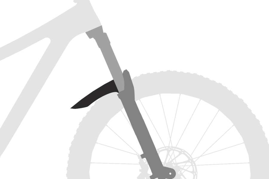
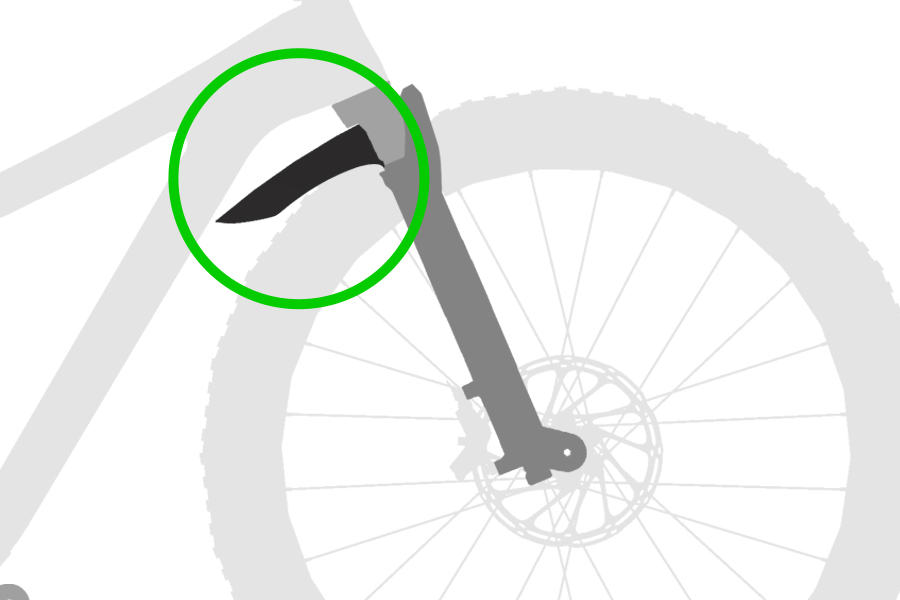
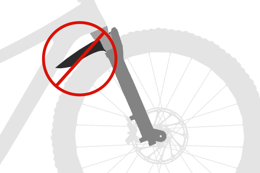
CRASH HAZARD: Parts must be tightened to the specified torque. Failure to do so can result in SERIOUS INJURY OR DEATH.
CRASH HAZARD: To avoid the potential of a crash, confirm the suspension fork fender does not contact the bicycle frame when the handlebar is turned from side to side.
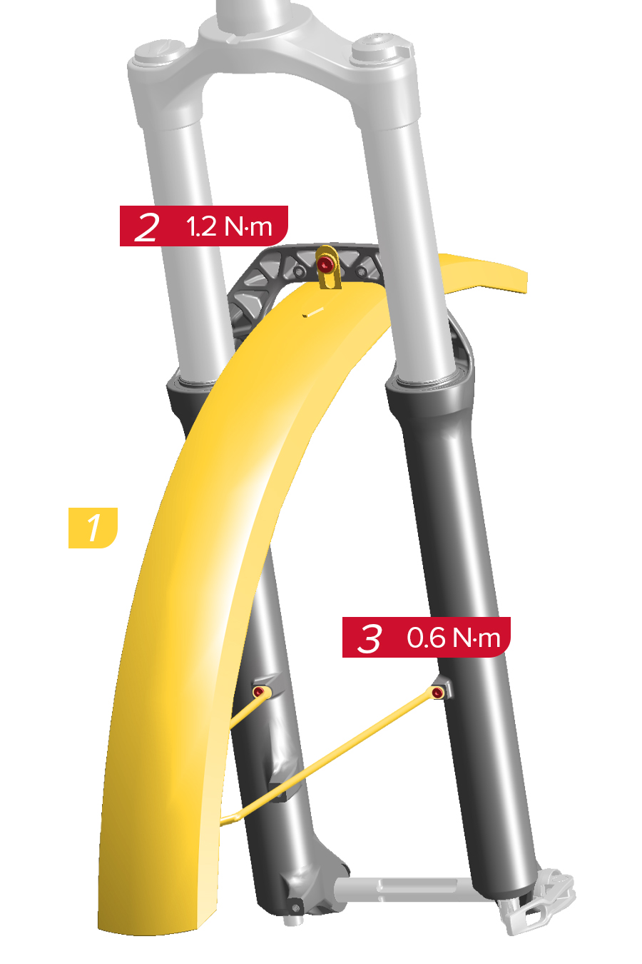
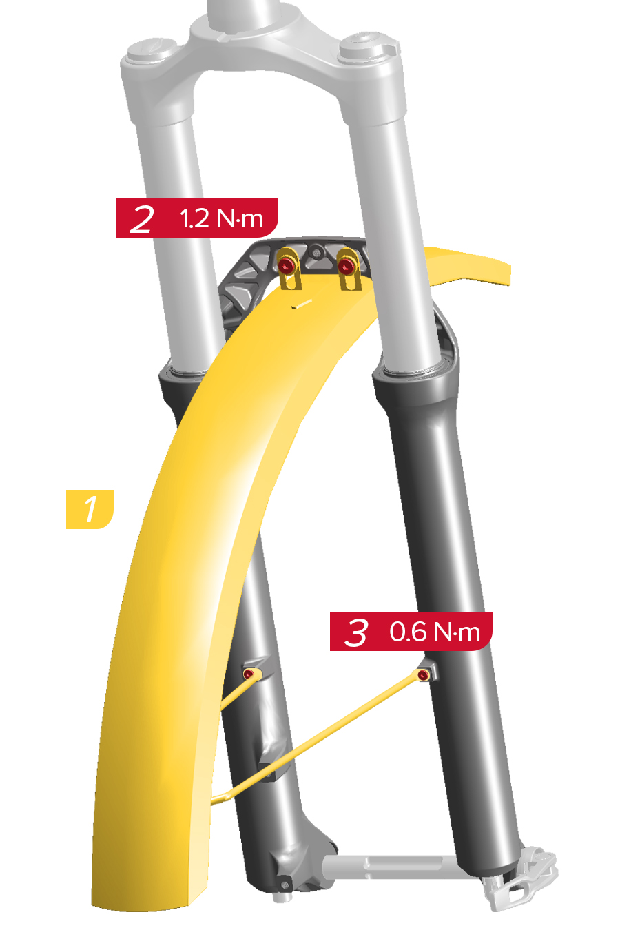
To avoid damage to the lower leg bolt hole threads, do not exceed the maximum torque as specified.
After the fender is installed, depressurize the air spring or remove the coil spring. Compress the fork to full bottom out, turn the handlebars side to side, and check for fender clearance at the bicycle frame down tube, fork crown, and tire. If there is any contact, adjust as needed, or remove the fender from the fork.
RockShox forks may be compatible with a variety of aftermarket fenders. Install the fork fender according to the manufacturer's instructions.
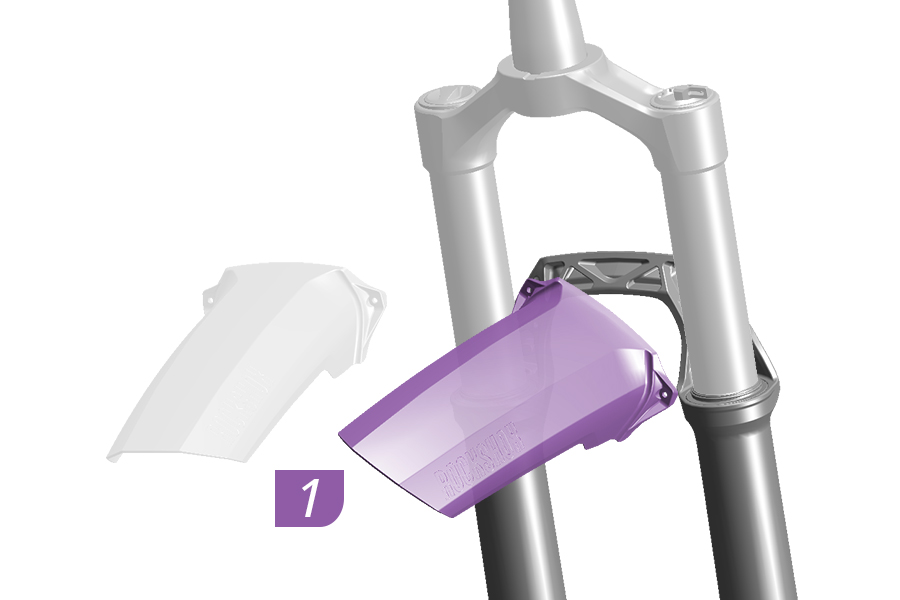
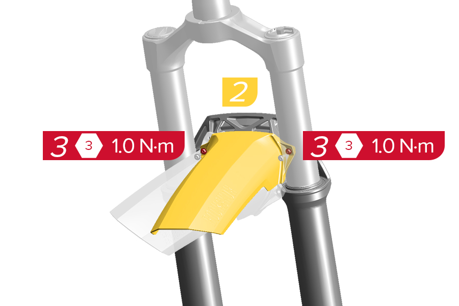
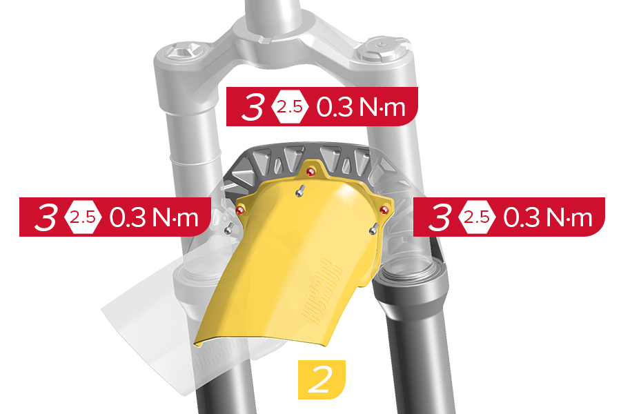
1-2. Position the fender onto the back of the fork arch, with the bolt holes aligned.
3. Install and tighten the bolts to the specified torque.
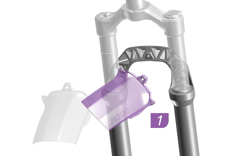
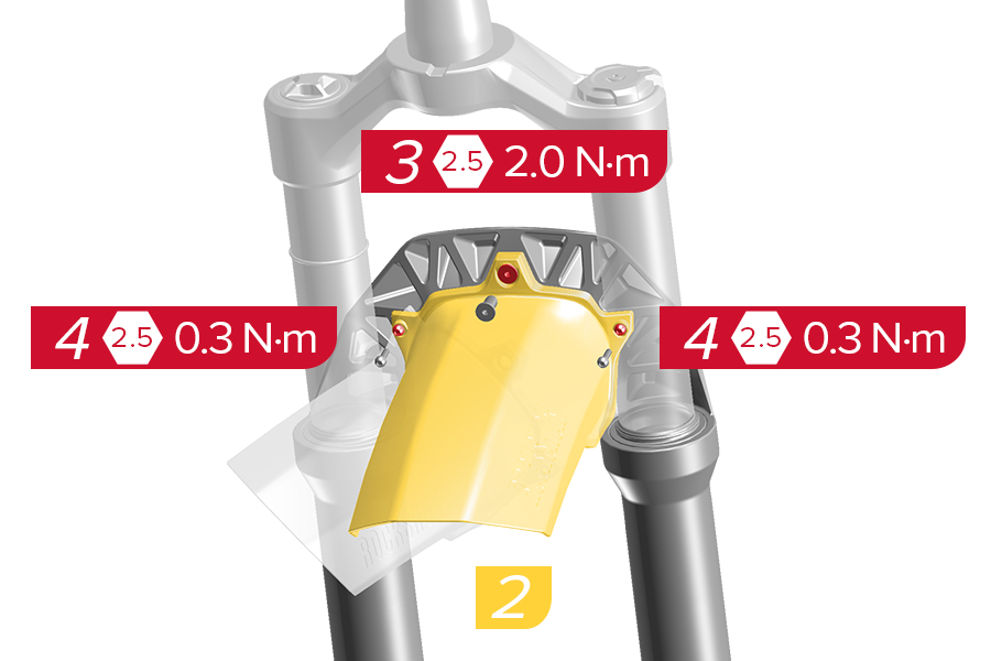
1-2. Position the fender onto the back of the fork arch, with the bolt holes aligned.
3-4. Install and tighten the bolts to the specified torque.
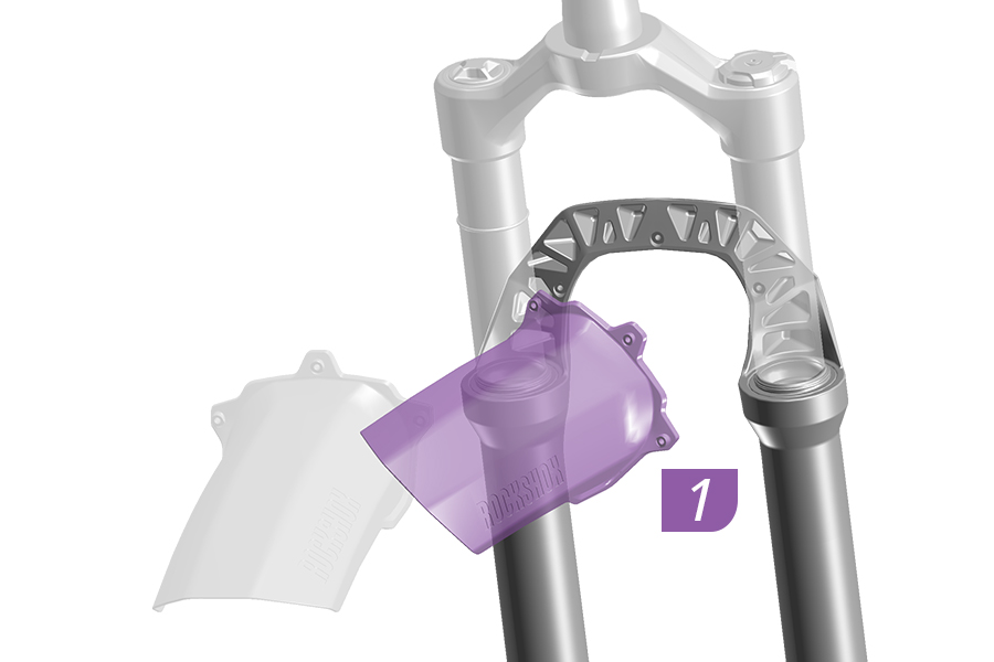
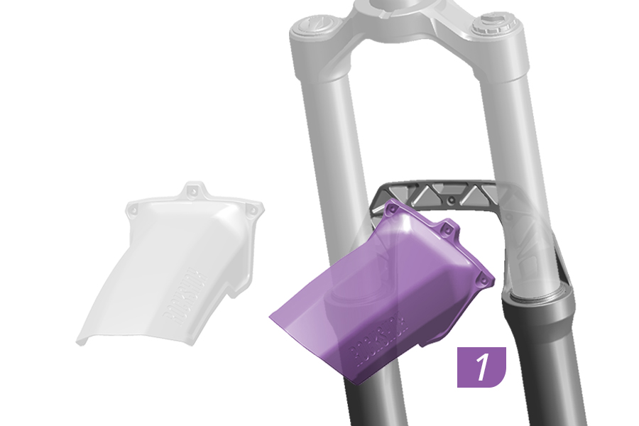
1-2. Position the fender onto the back of the fork arch, with the bolt holes aligned.
3. Install and tighten the bolts to the specified torque.
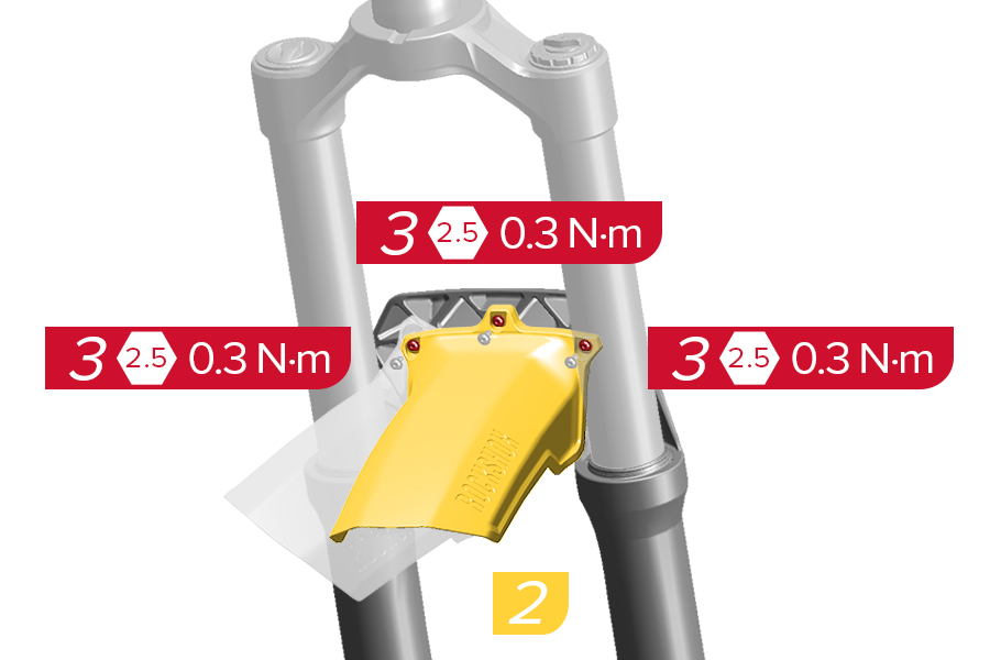
1-2. Position the fender onto the back of the fork arch, with the bolt holes aligned.
3. Install and tighten the bolts to the specified torque.
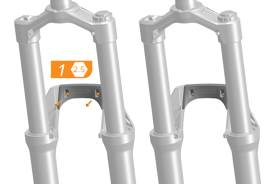
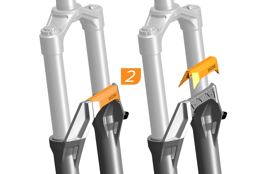
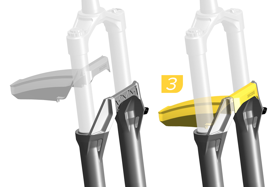
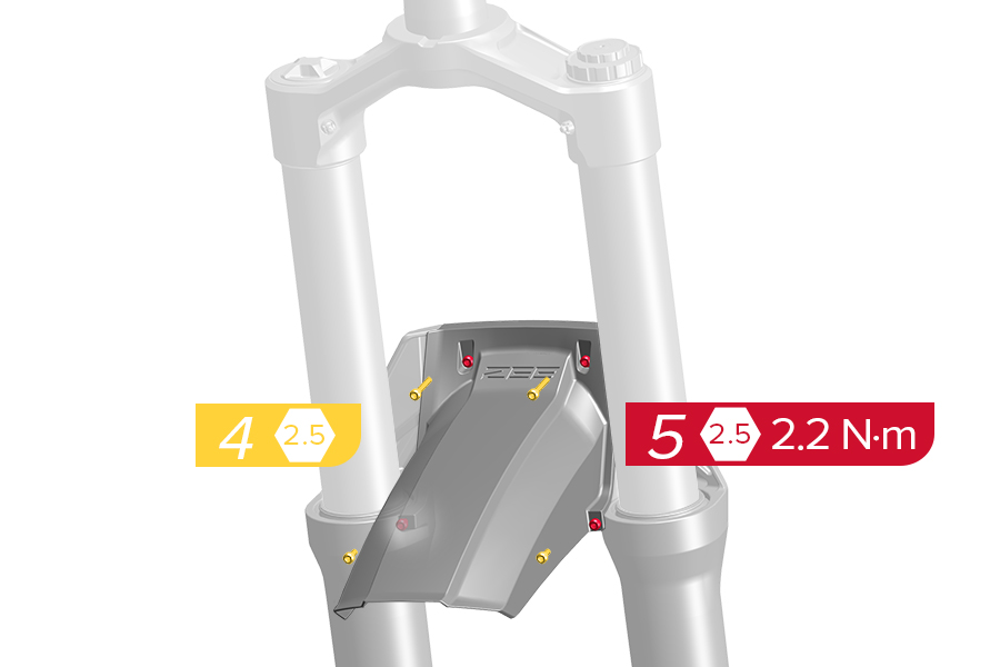
1. Remove the lower arch cover cap bolts.
2. Remove the lower arch cover cap.
3. Install the fender.
4. Install the fender bolts and tighten each bolt to the specified torque.
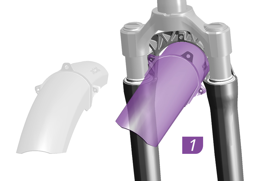
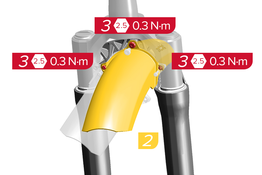
1-2. Position the fender onto the back of the fork arch, with the bolt holes aligned.
3. Install and tighten the bolts to the specified torque.
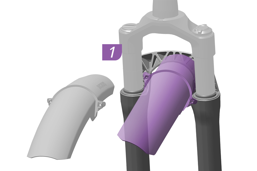
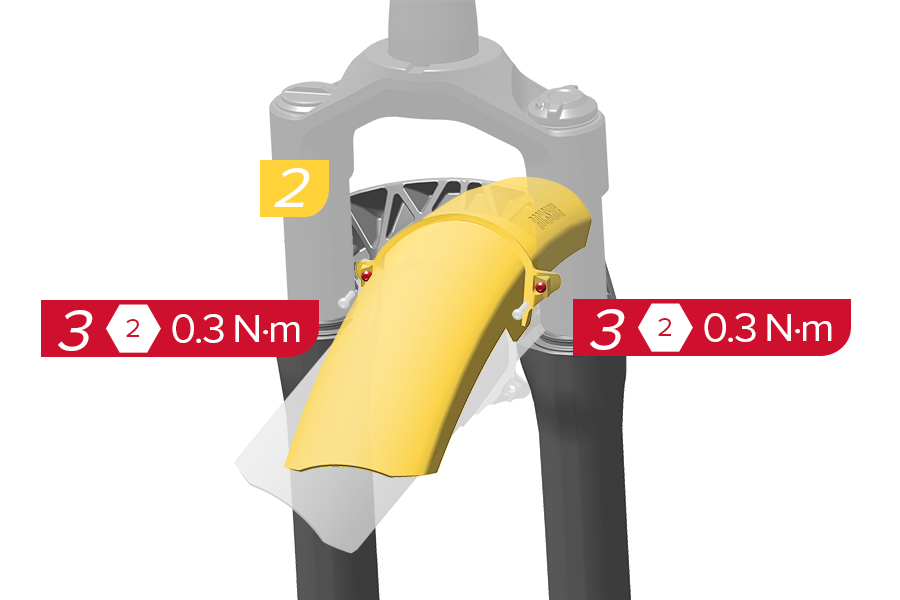
1-2. Position the fender onto the back of the fork arch, with the bolt holes aligned.
3. Install and tighten the bolts to the specified torque.
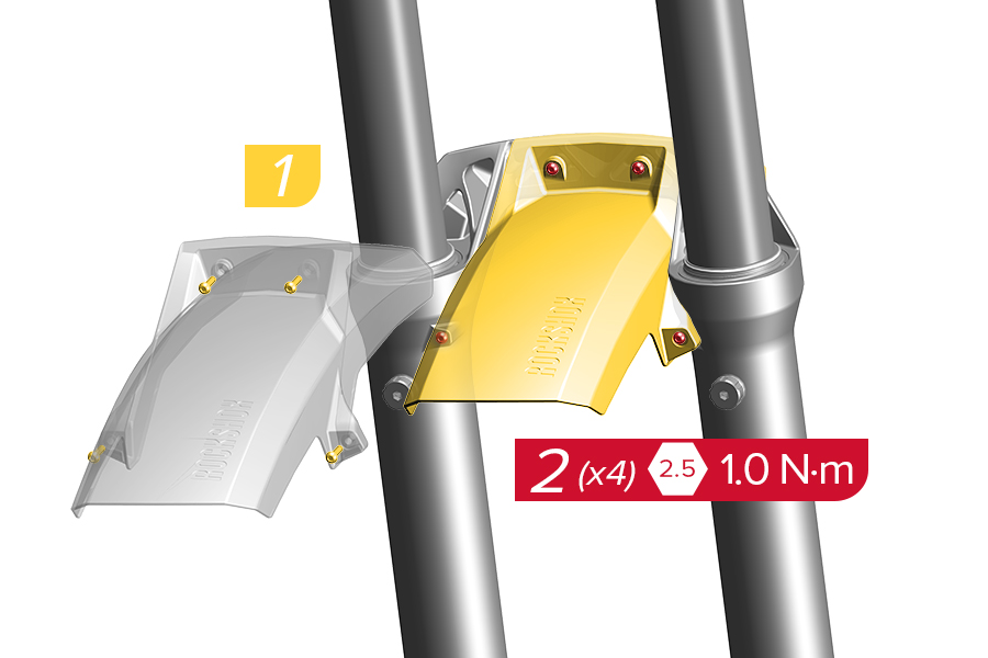
1. Position the fender onto the back of the fork arch, with the bolt holes aligned.
2. Install and tighten the bolts to the specified torque.
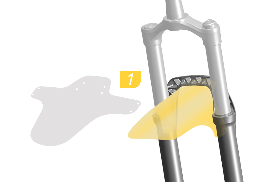
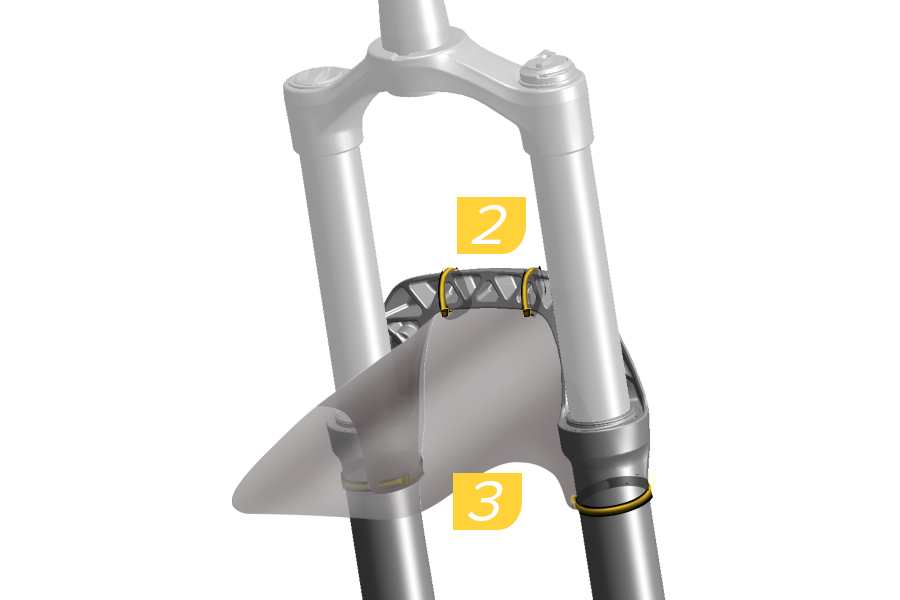
All RockShox forks are compatible with the RockShox MTB, and a variety of aftermarket, cable tie attached fenders.
Optional: To protect lower leg paint, install clear anti-abrasion tape to the lower leg where the fender and cable ties will contact paint.
1. Align the cable tie holes with the fork arch and each lower leg.
2-3. Secure the fender to the fork arch and each lower leg with cable ties. Confirm the cable ties are tight and the fender does not move. Cut the excess from each cable tie.
Damage from abrasion is not covered under warranty. To avoid damage to lower leg paint and magnesium from abrasion, rinse the fork and fender with water after each ride. Periodically remove the fender, clean the fork and fender, and reinstall with new cable ties.
Some RockShox forks are compatible with a variety of aftermarket bolt-on fenders. RockShox does not produce the bolt-on fender pictured. Install the fork fender according to the manufacturer's instructions.
To avoid damage to the lower leg bolt hole threads, do not exceed the maximum torque as specified.
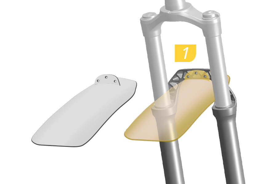
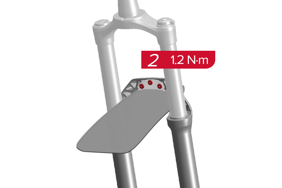
1. Align the bolt holes and install the fender onto the fork.
2. Tighten the bolts to the specified torque.
Some RockShox forks are compatible with a variety of aftermarket bolt-on fenders with fender stays. RockShox does not produce bolt-on fenders with fender stays.
Install the fork fender according to the manufacturer's instructions.
CRASH HAZARD: Parts must be tightened to the specified torque. Failure to do so can result in SERIOUS INJURY OR DEATH.
CRASH HAZARD: To avoid the potential of a crash, there must be at least 6 mm clearance from the fender stay and the tire sidewall, and 6 mm between the fender stay and the disc brake caliper.
To avoid damage to the lower leg bolt hole threads, do not exceed the maximum torque as specified.
1. Align the bolt holes and install the fender and fender stays onto the fork.
2-3. Tighten the fender and fender stay bolts to the specified torque.
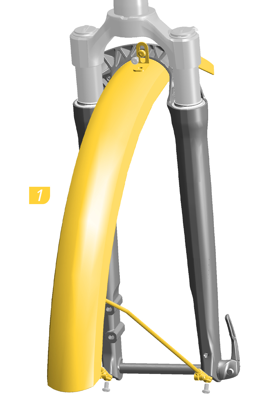
.JPG)
1. Align the bolt holes and install the fender and fender stays onto the fork lower leg.
2-3. Tighten the fender and fender stay bolts to the specified torque.
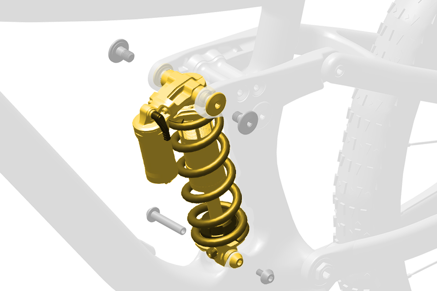
Bicycle frames and rear shocks vary. Consult the bicycle frame manufacturer for the correct rear shock eyelet interface, mounting hardware, and proper installation of your rear shock.
Configurations and features vary by shock model. Go to RockShox for additional product information.
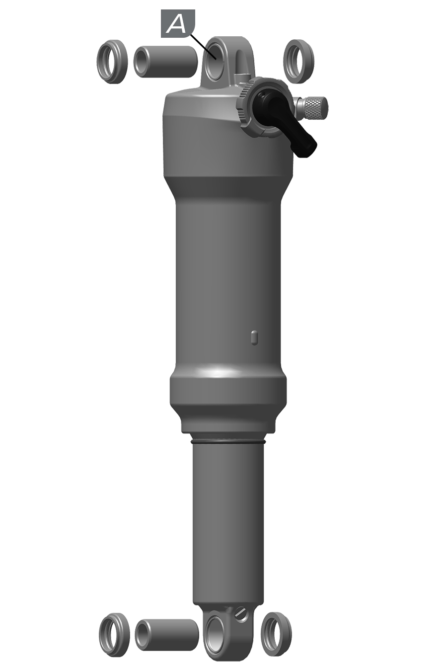
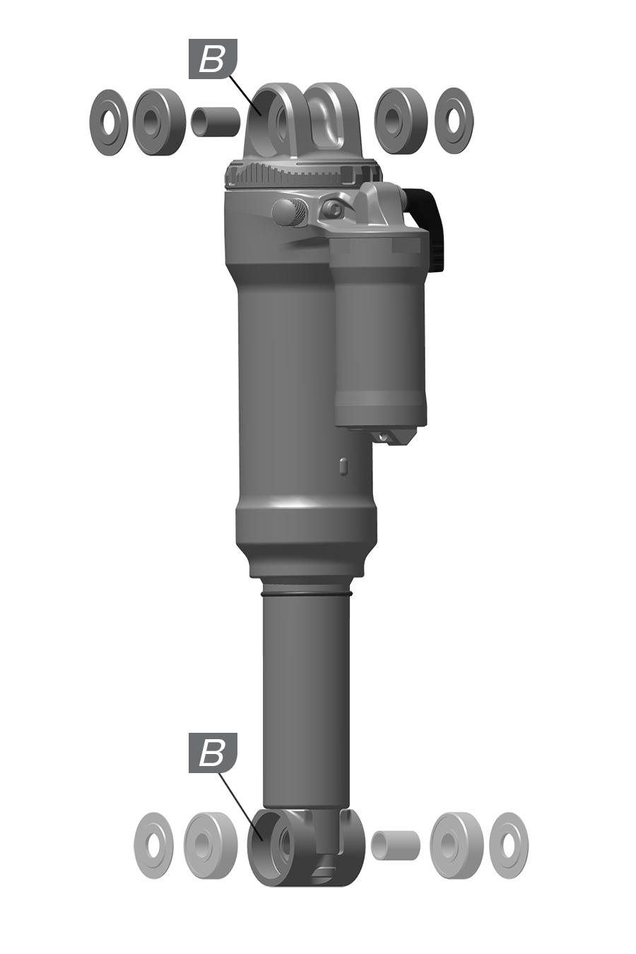
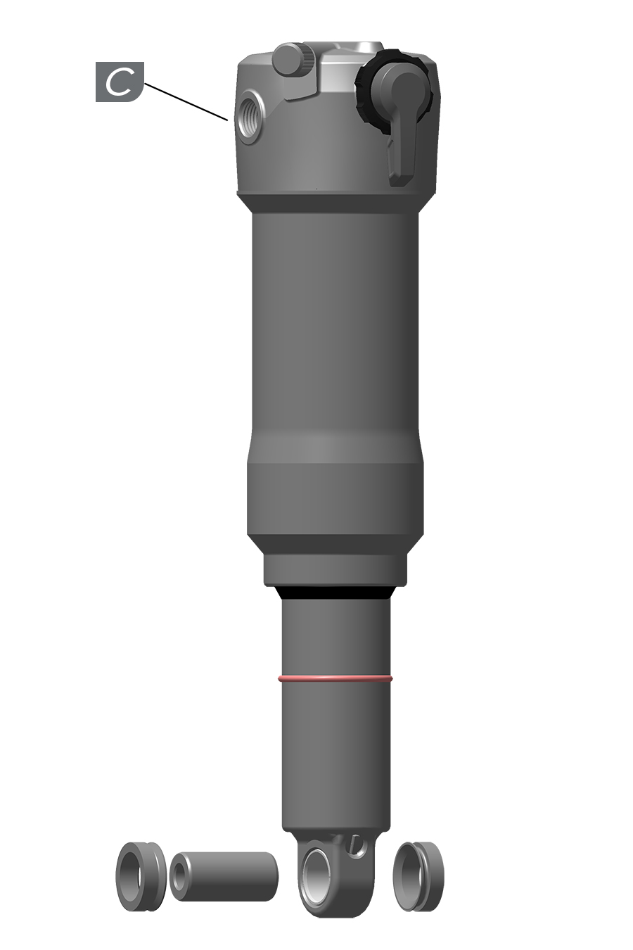
Consult the bicycle frame manufacturer for rear shock compatibility, specifications, and installation requirements.
Use the RockShox Rear Shock Bushing Tool to install 3-piece spacer mounting hardware.
Refer to the (RockShox) Spare Parts Catalog for available mount hardware.
Consult the frame manufacturer for required mount hardware sizes for each shock eyelet.
To avoid damage to the rear shock and/or bicycle frame, do not install the incorrect size mount hardware.
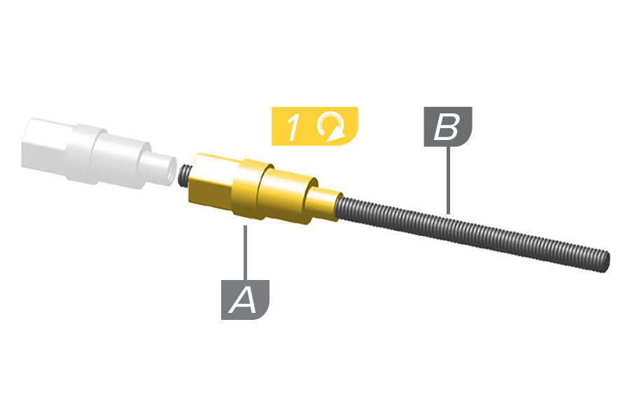
1. Thread the small end of the push pin (A) onto the threaded rod (B) until the rod protrudes from the hex-shaped end of the push pin.
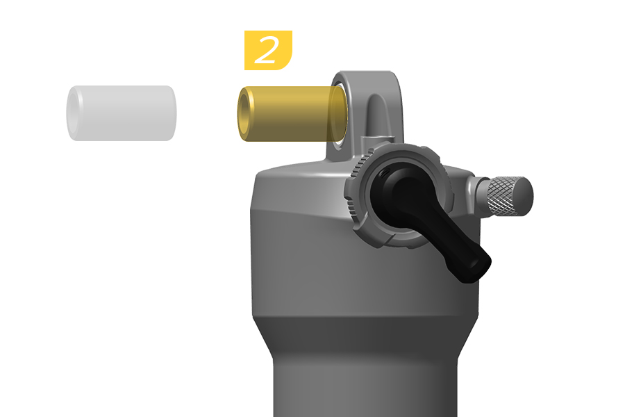
2. Insert the pin into the eyelet bushing.
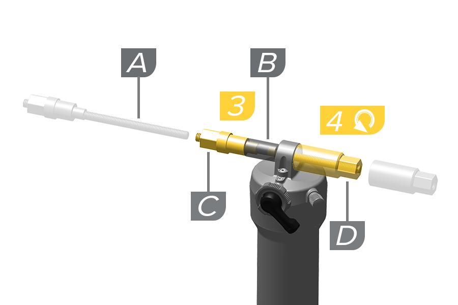
3. Insert the threaded rod (A) through the bushing pin (B), then through the shaft eyelet so that the bushing pin is positioned between the push pin (C) and the shock eyelet.
4. Thread the large, open end of the catcher (D) onto the threaded rod (A) until the catcher rests on the shock eyelet.
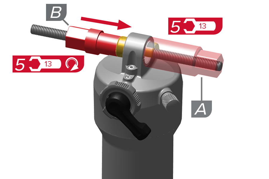
5. Hold the catcher (A) secure with a 13 mm wrench, or clamp the catcher vertically in a vise.
While holding the shock secure so it does not rotate, use a second 13 mm wrench to thread the push pin (B) along the rod until it pushes the bushing pin into the shock eyelet bushing.
To avoid damage to the rear shock, hold the shock secure and do not allow it to rotate against the RockShox Rear Shock Bushing Tool Catcher during mount hardware eyelet pin (and/or eyelet bushing) installation.
Use one mount hardware spacer to check the pin position. The pin should be centered in the eyelet and the end of the spacer should be flush with the end of the pin. Remove the spacer if the pin is not centered.
Continue to thread the push pin until the bushing pin protrudes from both sides of the eyelet an equal amount.
You may need to unthread the catcher slightly to check the bushing pin spacing.
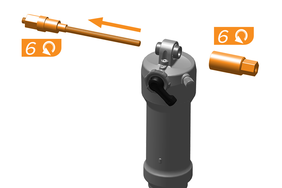
6. Remove the bushing tool.
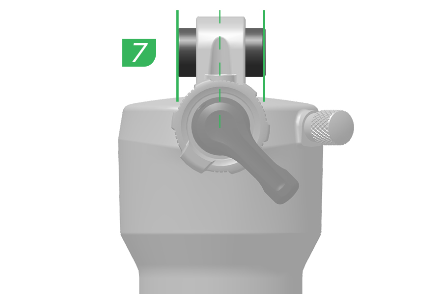
7. Confirm the mount hardware spacer pin is centered in the eyelet.
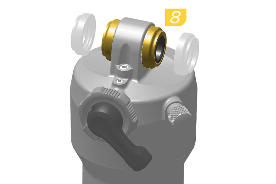
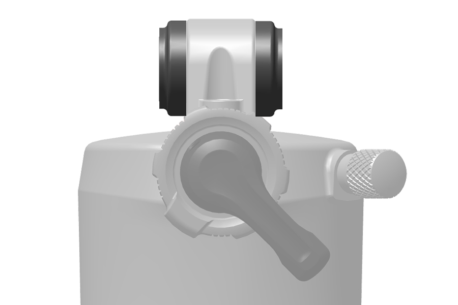
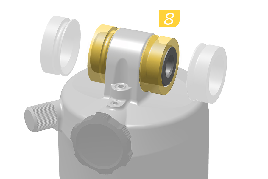
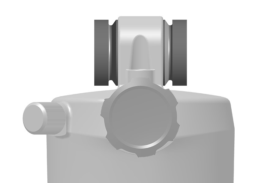
8. Press a spacer onto each end of the bushing pin in the corrected orientation.
Spacer V1 - Install tapered end outward.
Spacer V2 - Install tapered end inward. The bushing pin should be centered in the eyelet and no portion of either end should protrude from either end spacer. Re-center the bushing pin if necessary.
Consult the manufacturer of your frame for the recommended coil spring rate.
Install a spring with the correct spring rate, and rotate the spring preload adjuster to increase or decrease spring preload.
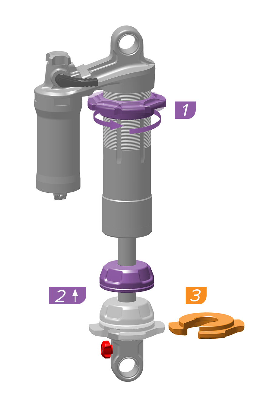
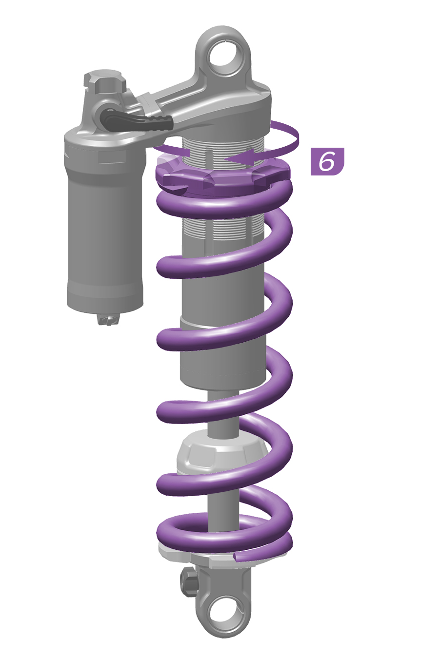
1. Rotate the spring preload collar toward the damper body eyelet.
2. Slide the bottom out bumper away from the shaft eyelet.
3. Remove the spring collar.
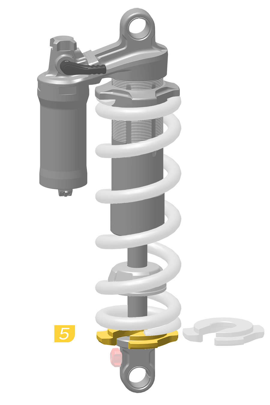
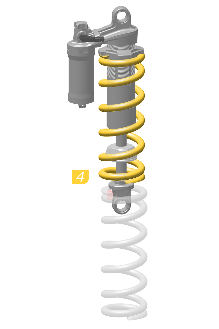
4. Install the spring.
5. Install the spring collar.
6. Rotate the spring preload collar until it contacts the spring. Rotate the preload collar one addition full rotation. Preload adjustment should be performed during the Set Sag process.
Suspension air pressure (DebonAir+), proper sag (Coil, Solo Air, DebonAir, Dual Position Air), and damper settings affect suspension performance. Set spring rate, air pressure, or sag before making any other tuning adjustments. Adjust rebound and compression dampers after spring rates have been set. Refer to each damping section for details.
Configurations and features vary by fork or shock model. Go to sram.com for additional product information.
Visit RockShox Trailhead for recommended starting air pressure and rebound damper settings.
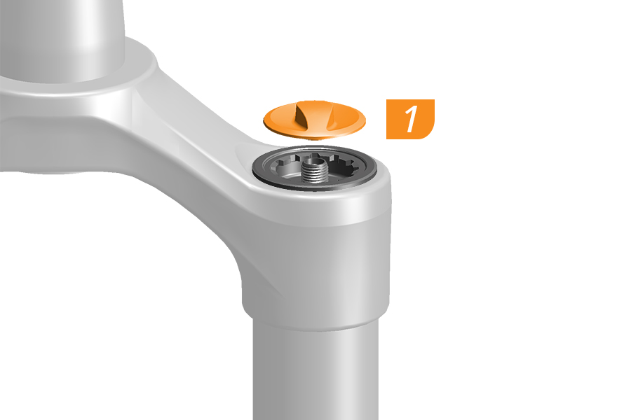
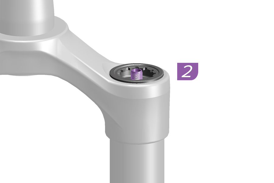
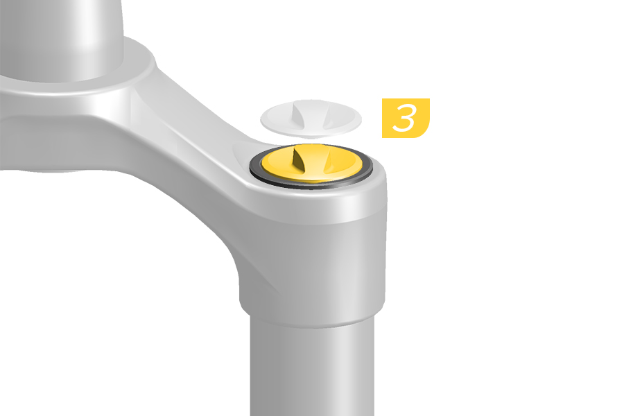
1. To adjust air spring pressure, remove the air cap.
2. Attach a high pressure shock pump to the air inflation valve and inflate to the recommended starting pressure.
3. Install the air cap.
See the air pressure decal on the fork or visit RockShox Trailhead for recommended starting air pressure settings.
1. To adjust air spring pressure, remove the air cap.
2. Attach a high pressure shock pump to the air inflation valve and inflate to the recommended starting pressure.
3. Install the air cap.
See the air pressure decal on the fork or visit RockShox Trailhead for recommended starting air pressure settings.
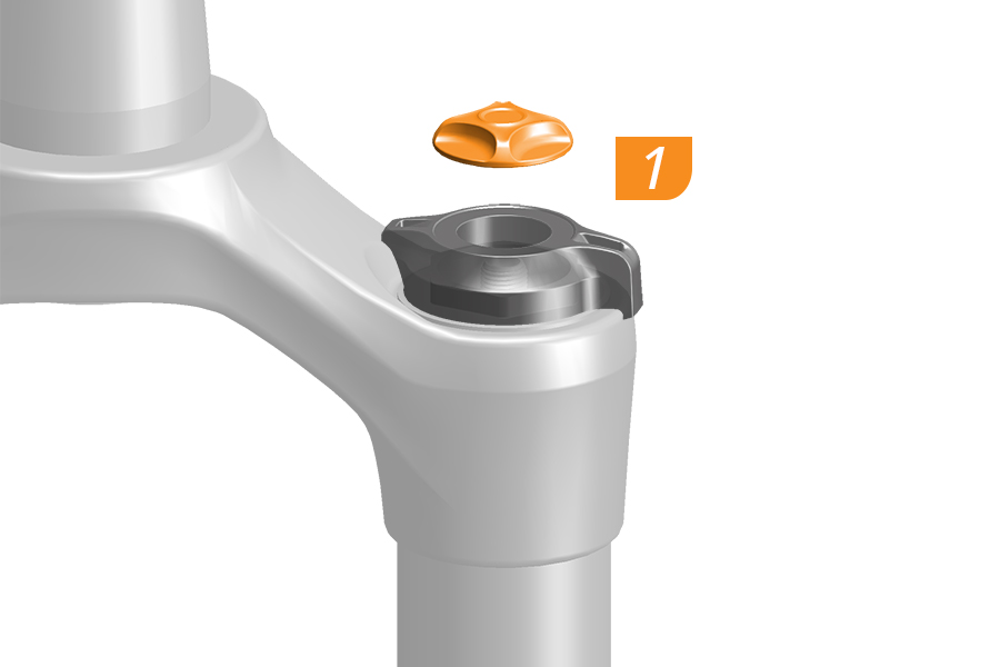
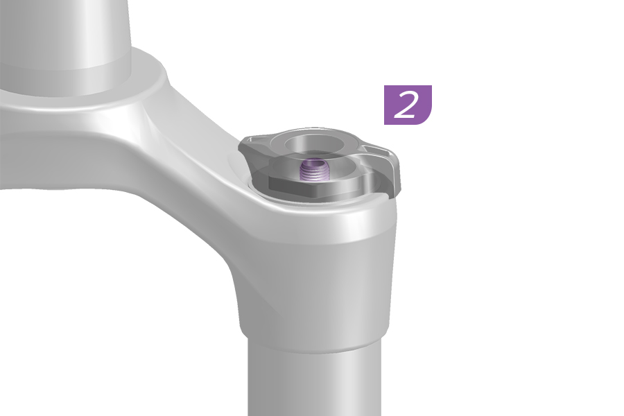
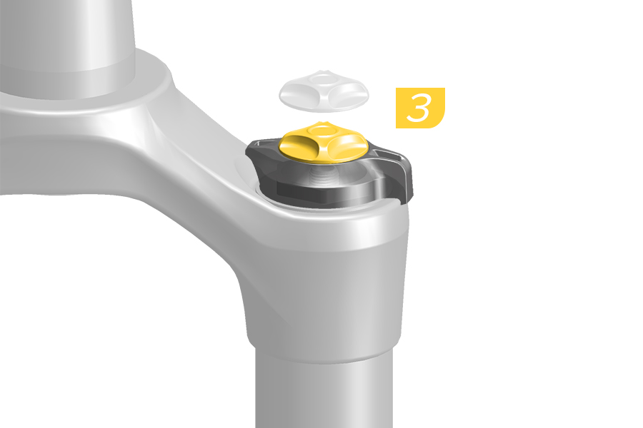
Pressurize a Dual Position Air fork in the full travel position. Refer to 'Dual Position Spring Travel - Front Suspension' for travel adjustment procedures.
1. To adjust air spring pressure, remove the air cap.
2. Attach a high pressure shock pump to the air inflation valve and inflate to the recommended starting pressure.
3. Install the air cap.
See the air pressure decal on the fork or visit RockShox Trailhead for recommended starting air pressure settings.
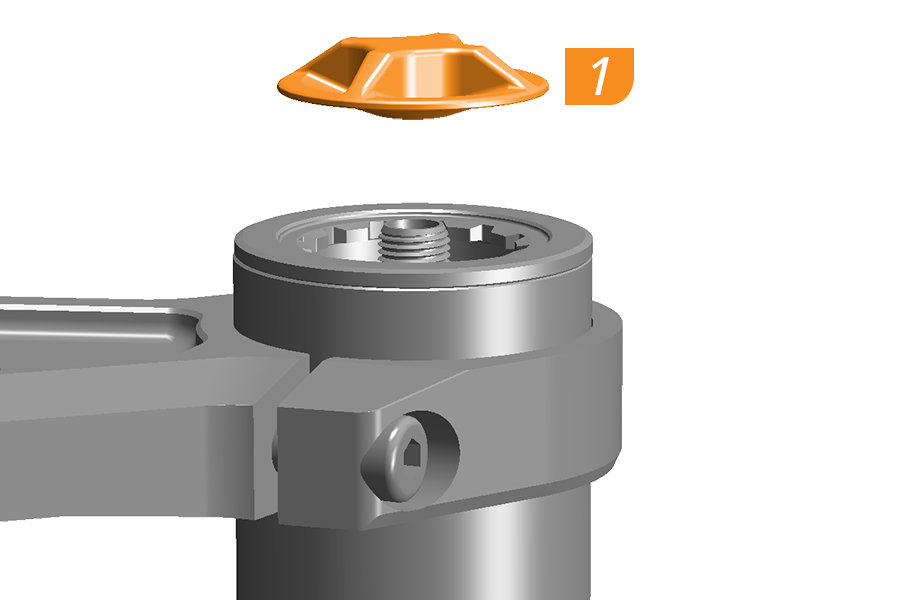
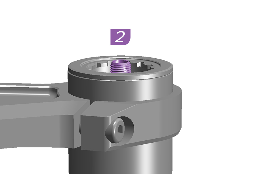
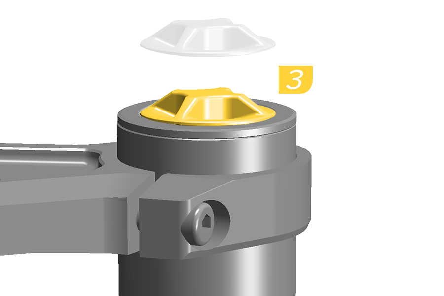
1. To adjust air spring pressure, remove the air cap.
2. Attach a high pressure shock pump to the air inflation valve and inflate to the recommended starting pressure.
3. Install the air cap.
See the air pressure decal on the fork or visit RockShox Trailhead for recommended starting air pressure settings.
1. To adjust air spring pressure, remove the air cap.
2. Attach a high pressure shock pump to the air inflation valve and inflate to the recommended starting pressure.
3. Install the air cap.
See the air pressure decal on the fork or visit RockShox Trailhead for recommended starting air pressure settings.
Most RockShox coil spring forks include a medium (red) spring rate standard. Tuning springs are available separately.
If after completing the spring sag procedure, the installed spring is not optimal, install a spring with the correct spring rate.
Refer to the (RockShox) Spare Parts Catalog for available tuning springs, and refer to your fork's service manual for spring removal and installation procedures.
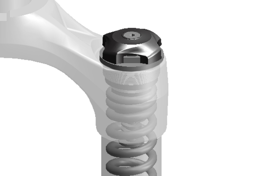
See the Set Sag-Coil Spring-External Preload Adjust section for more details.
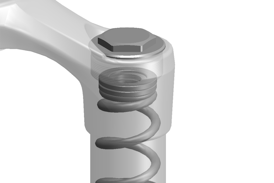
See the Set Sag-Coil Spring-Preload Spacers section for more details.
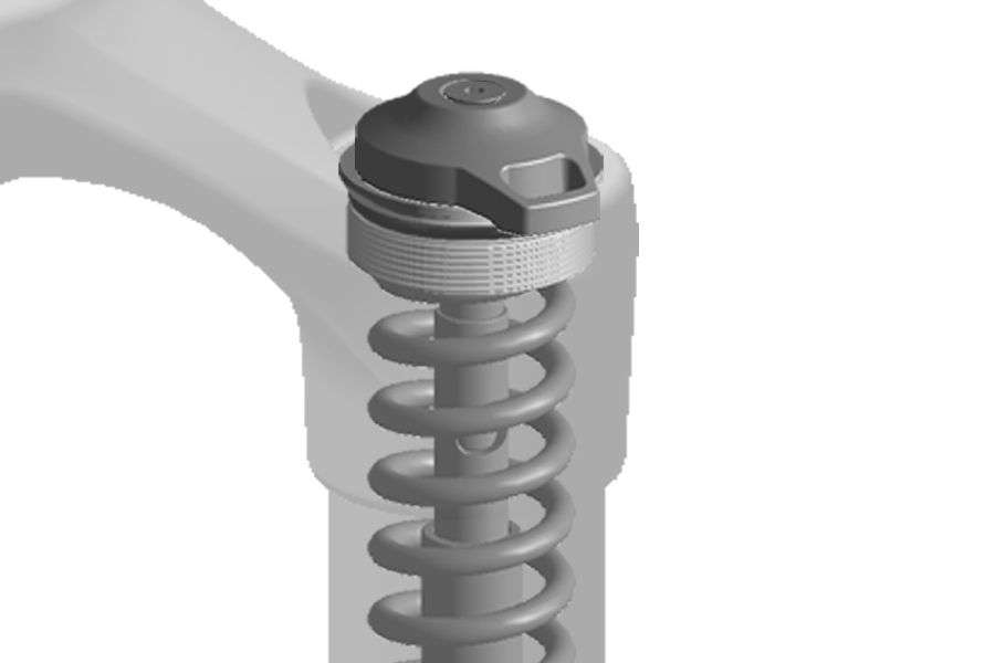
Spring sag is not adjustable. Medium spring rate is standard.
To decrease sag and increase spring rate, the coil spring assembly must be replaced with an X-Firm spring assembly.
See the (RockShox) Spare Parts Catalog for available spring kits.
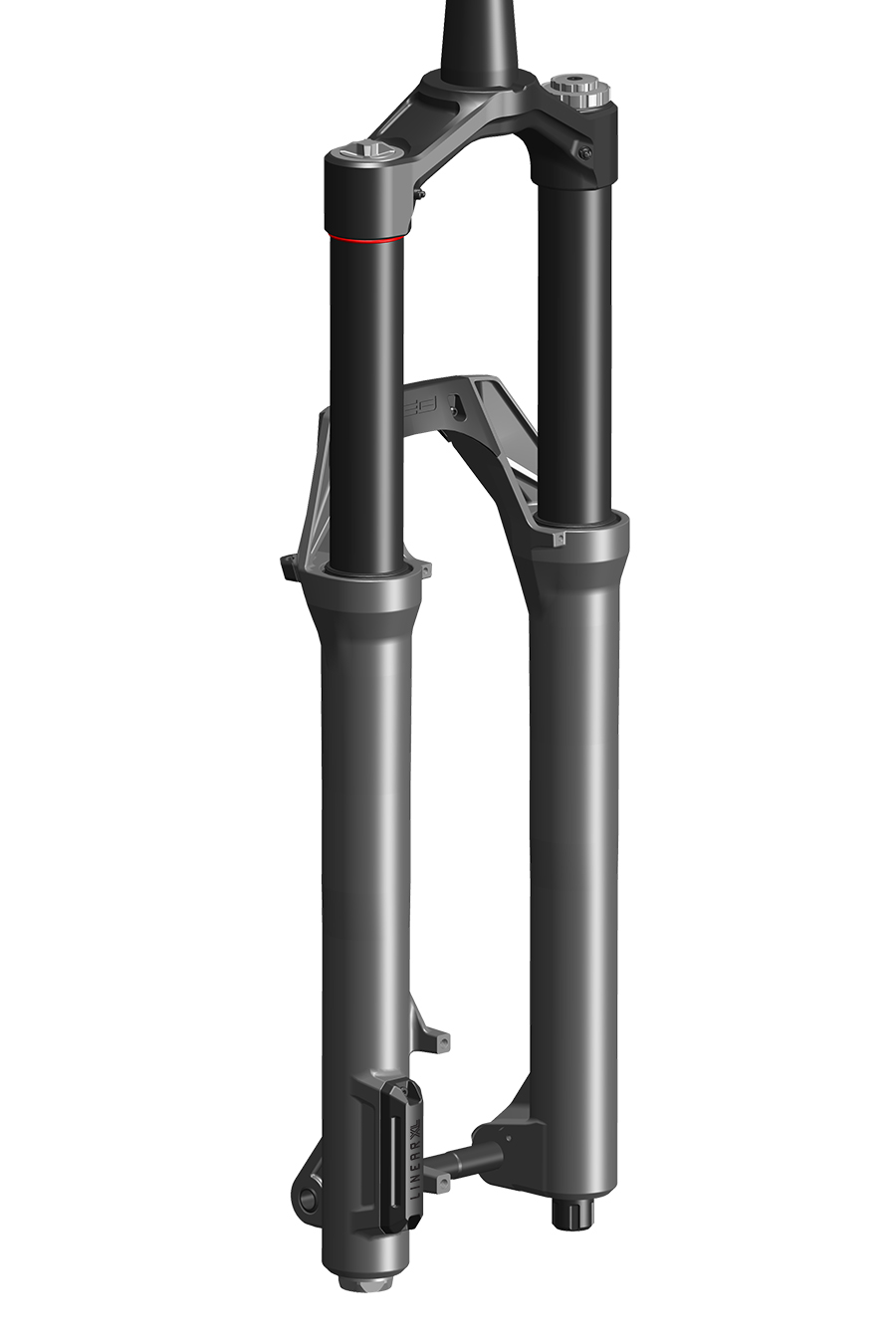
Optimal Linear XL air spring pressure results in small bump sensitivity, mid-stroke support, and the use of full travel. Setting Linear XL air spring pressure does not require the 'Set Sag' procedure.
After pressurizing a Linear XL fork to the recommended starting pressure, adjust the dampers:
All Linear XL fork models: Adjust the rebound damper to the recommended setting (RockShox Trailhead).
Charger 3.2 Flight Attendant: Set the fork Control Module to the OPEN position, and adjust the Low Speed Compression (LSC) damper setting to the middle setting. Refer to the Flight Attendant User Manualfor damper and Control Module procedures.
Charger 3.2 RC2: Adjust the Low Speed Compression (LSC) damper setting to the middle setting.
Delta RC: Adjust Compression dampers to the OPEN setting.
Go for a test ride and make air pressure and damping adjustments as needed to achieve optimal performance.
Bottomless Tokens can be added or removed to further fine tune spring feel. Refer to the service manual for your fork for Bottomless Token quantities, and installation and removal procedures.
Getting started: Front suspension air pressure recommendations listed on the back of your fork, and at RockShox Trailhead, are suggestions for initial spring setup.
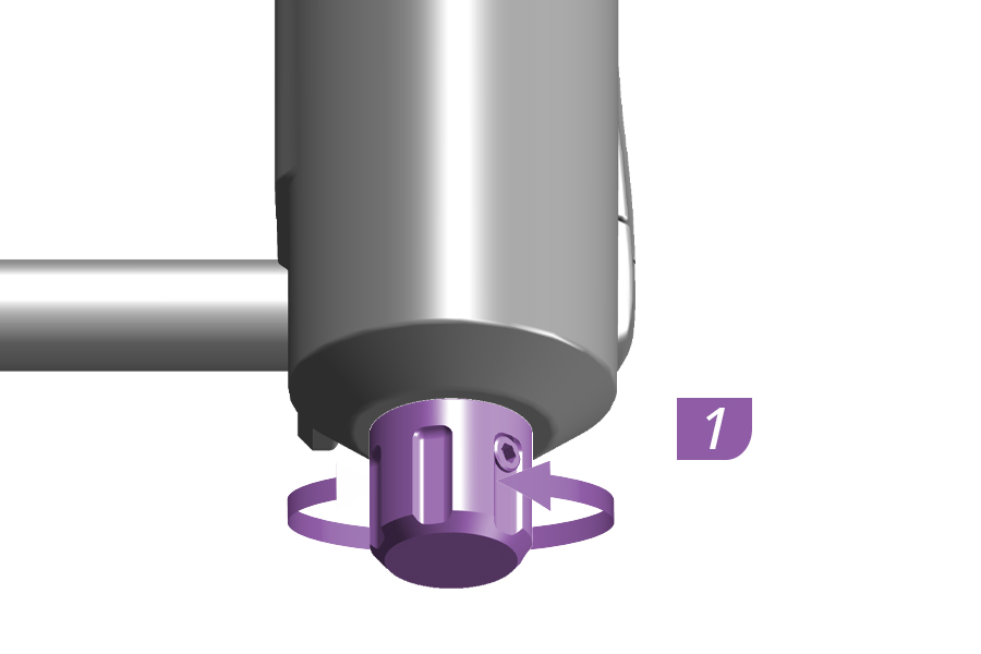
1. Adjust the rebound damper counterclockwise, to the full OPEN position.
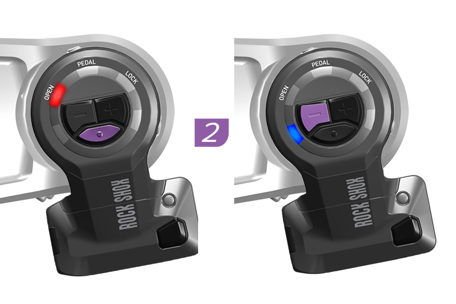
2. Set the fork Control Module to Manual Mode, set the suspension position to OPEN, and adjust Low Speed Compression damping to the lowest setting.
See the Flight Attendant User Manual for procedures.
3. Remove the air spring cap.
4. Pressurize the Linear XL air spring to 50% of the recommended pressure on the fork air pressure decal or at RockShox Trailhead.
Remove the pump. Do not compress the suspension with the pump attached.
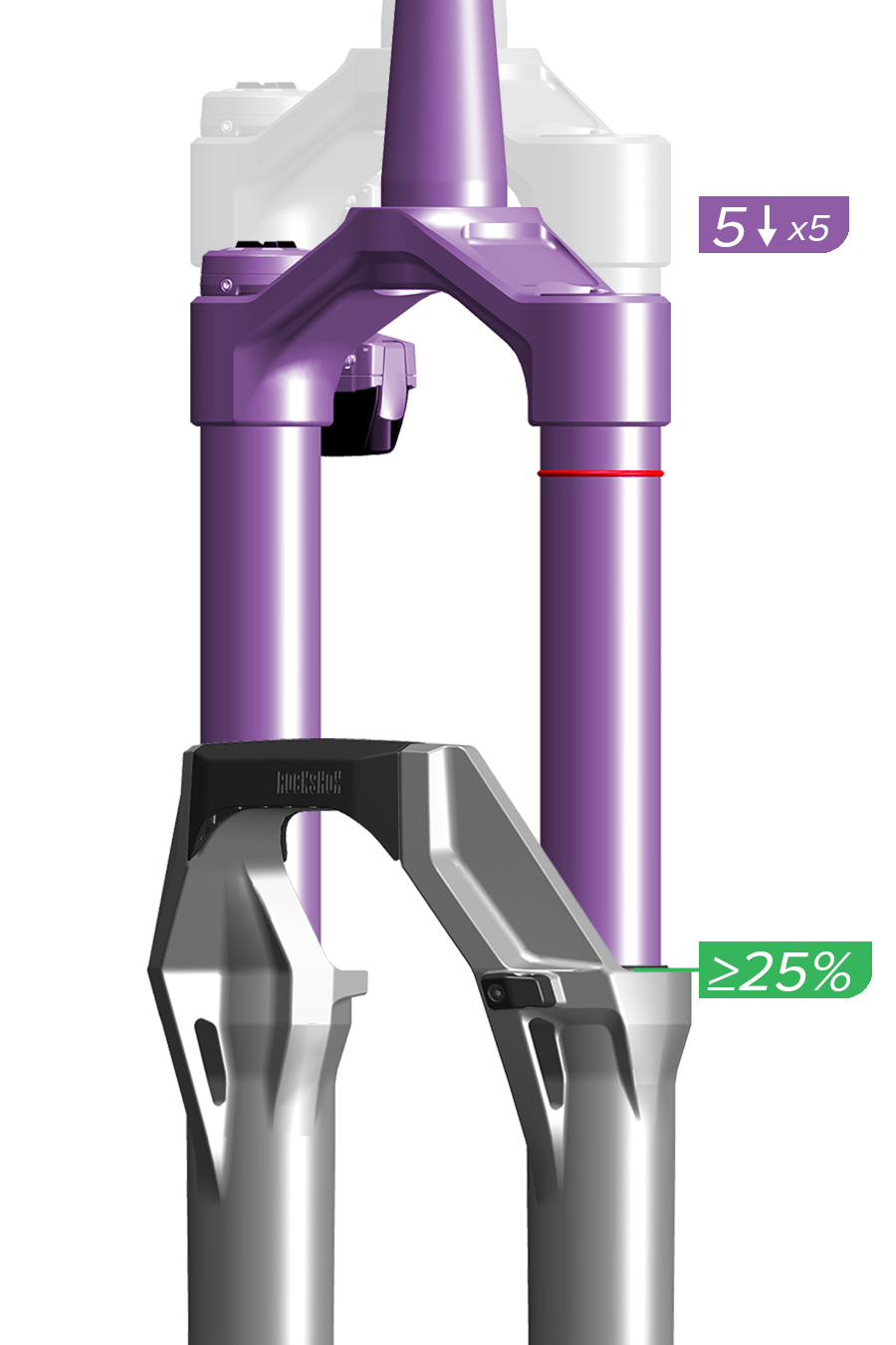
5. Slowly compress the fork (at least 3 seconds per compression) to 25% travel five times to equalize positive and negative air pressures.
Air pressure equalization ensures the air spring is accurately pressurized.
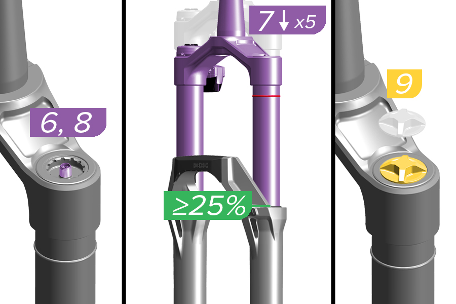
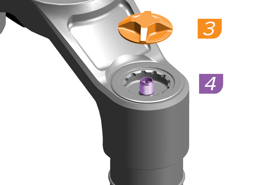
6. Pressurize the Linear XL air spring to 100% of the recommended pressure on the fork air pressure decal or at trailhead.rockshox.com. Remove the pump. Do not compress the suspension with the pump attached.
7. Slowly compress the fork (at least 3 seconds per compression) to 25% travel five times again to equalize positive and negative pressures.
8. Pressurize the Linear XL air spring once more to 100% of the recommended pressure on the fork air pressure decal or at RockShox Trailhead. Remove the pump.
9. Install the air cap.
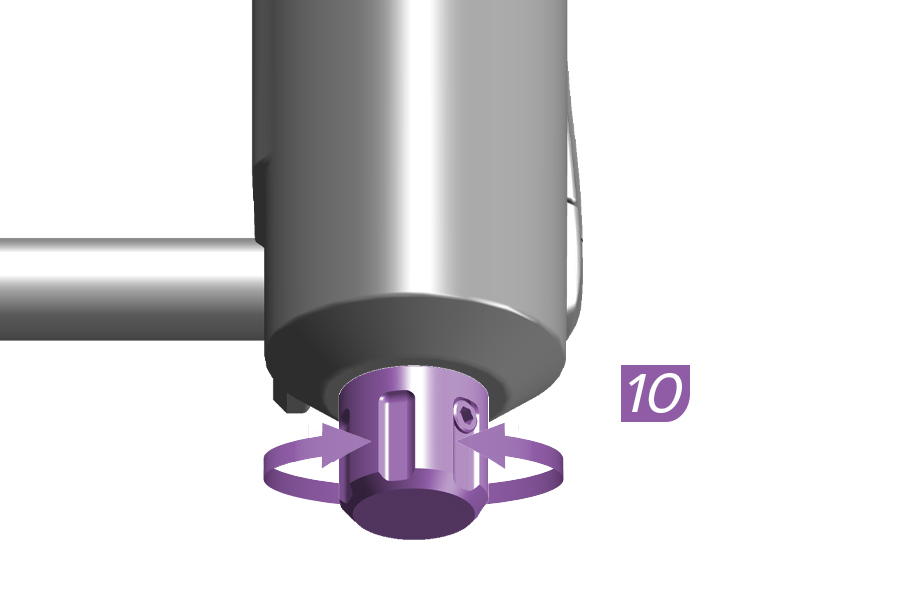
10. Adjust the rebound damper as recommended at RockShox Trailhead.
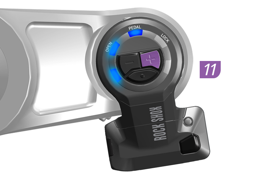
11. Adjust the Low Speed Compression (LSC) damper adjuster to the MIDDLE (5 or 6) setting to start.
See the Flight Attendant User Manual for procedures.
12. Go for a ride to test your air spring and damping settings. The fork should achieve full travel at optimal air spring pressure.
Adjust air spring pressure and damper settings as preferred.
Bottomless Tokens can be removed or installed to fine-tune spring feel.
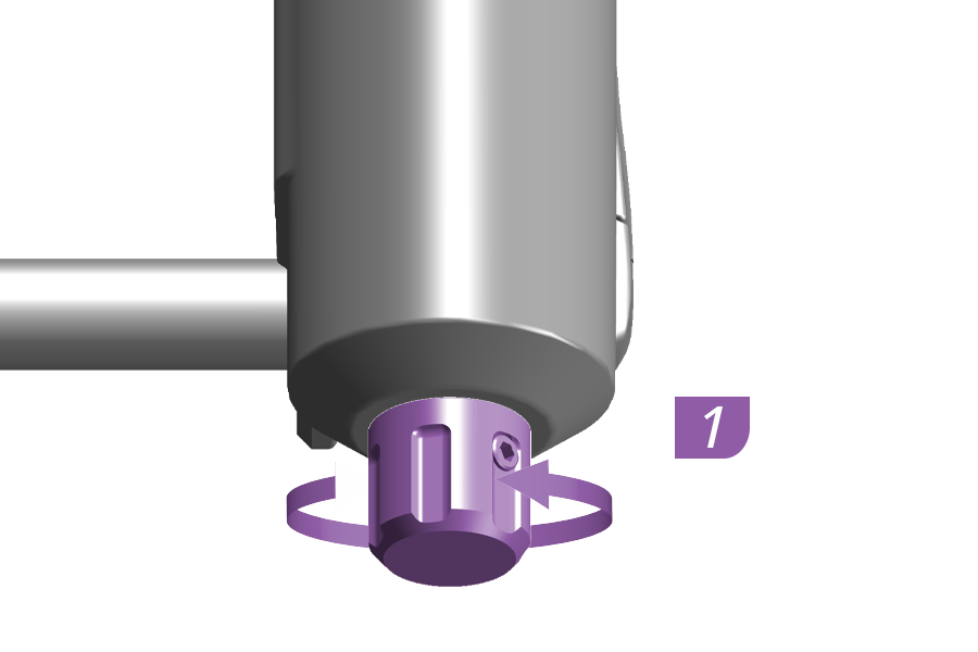
1. Adjust the rebound damper counterclockwise, to the full OPEN position.
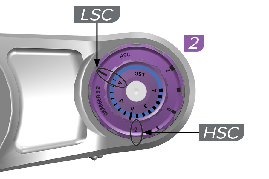
2. Adjust the compression damper(s) to the full OPEN setting(s).
Charger 3.2 RC2: Low Speed and High Speed
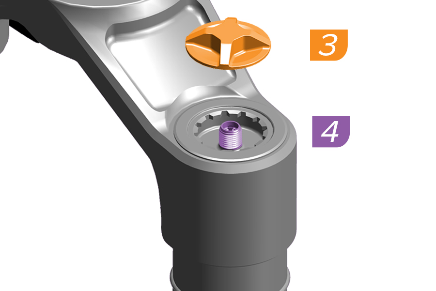
3. Remove the air spring cap.
4. Pressurize the Linear XL air spring to 50% of the recommended pressure on the fork air pressure decal or at RockShox Trailhead.
Remove the pump. Do not compress the suspension with the pump attached.
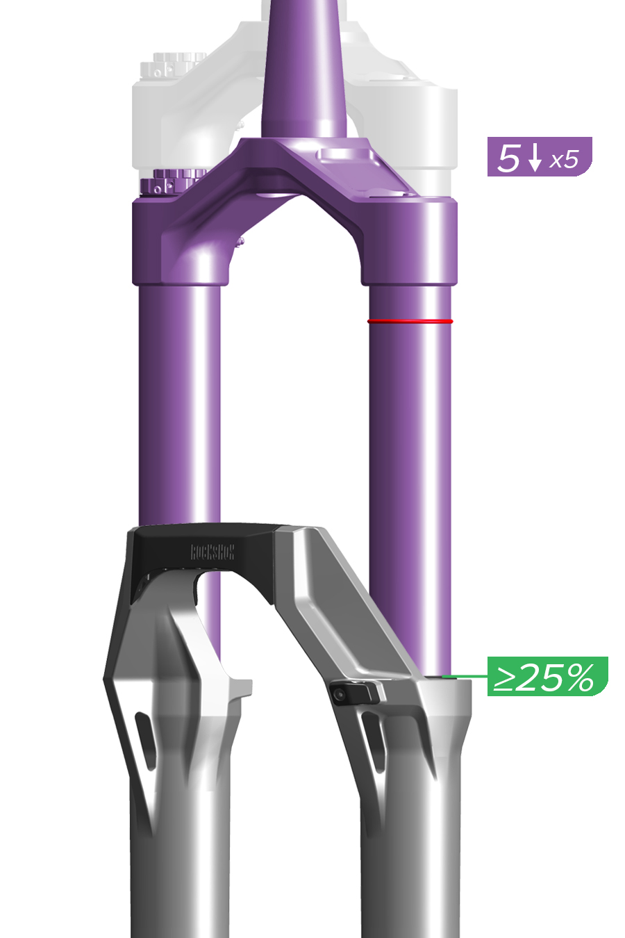
5. Slowly compress the fork (at least 3 seconds per compression) to 25% travel five times to equalize positive and negative air pressures.
Air pressure equalization ensures the air spring is accurately pressurized.
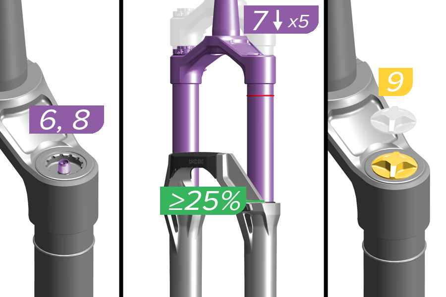
6. Pressurize the Linear XL air spring to 100% of the recommended pressure on the fork air pressure decal or at trailhead.rockshox.com. Remove the pump. Do not compress the suspension with the pump attached.
7. Slowly compress the fork (at least 3 seconds per compression) to 25% travel five times again to equalize positive and negative pressures.
8. Pressurize the Linear XL air spring once more to 100% of the recommended pressure on the fork air pressure decal or at trailhead.rockshox.com. Remove the pump.
9. Install the air cap.
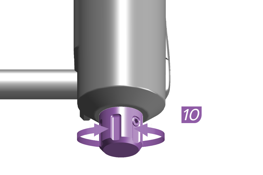
10. Adjust the rebound damper as recommended at RockShox Trailhead.
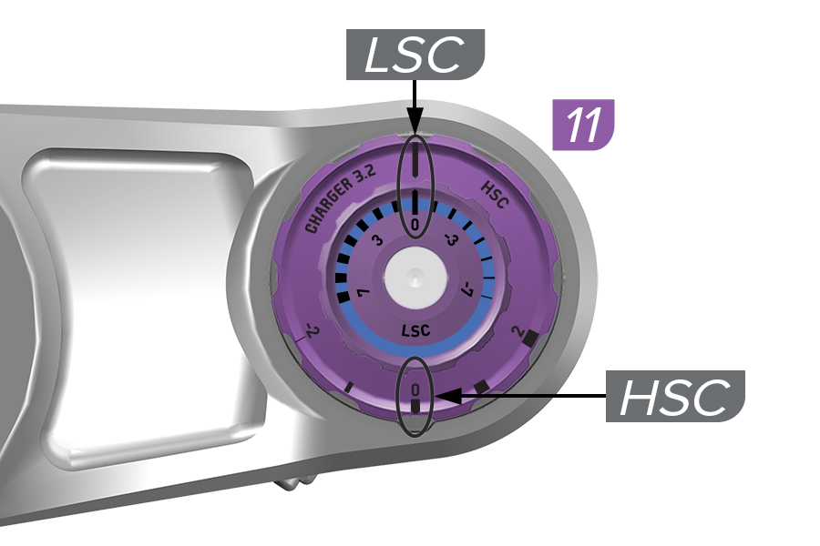
11. Adjust the Low speed (LSC) and High speed (HSC) compression damper adjusters to the MIDDLE settings to start.
12. Go for a ride to test your air spring and damping settings. The fork should achieve full travel at optimal air spring pressure.
Adjust air spring pressure and damper settings as preferred.
Bottomless Tokens can be removed or installed to fine-tune spring feel.
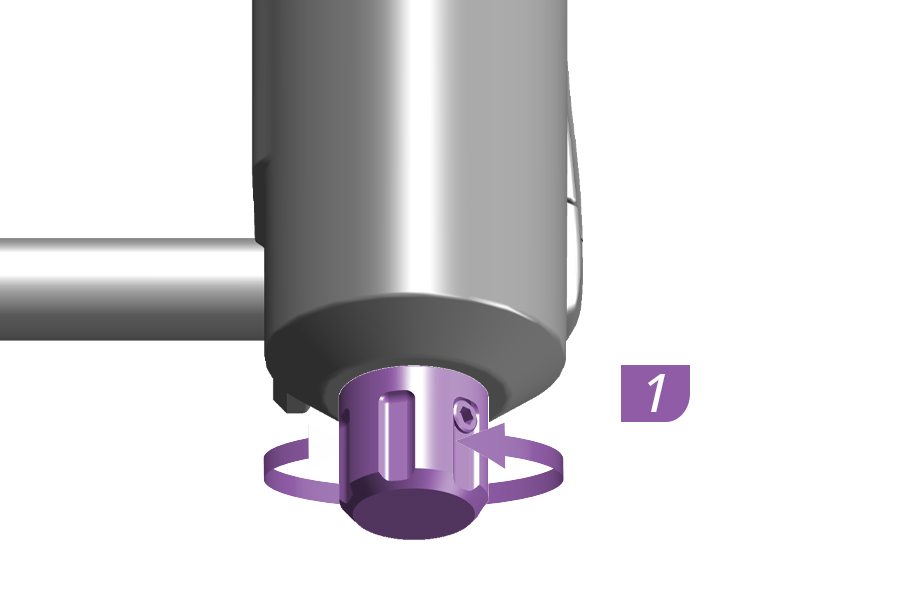
1. Adjust the rebound damper counterclockwise, to the full OPEN position.
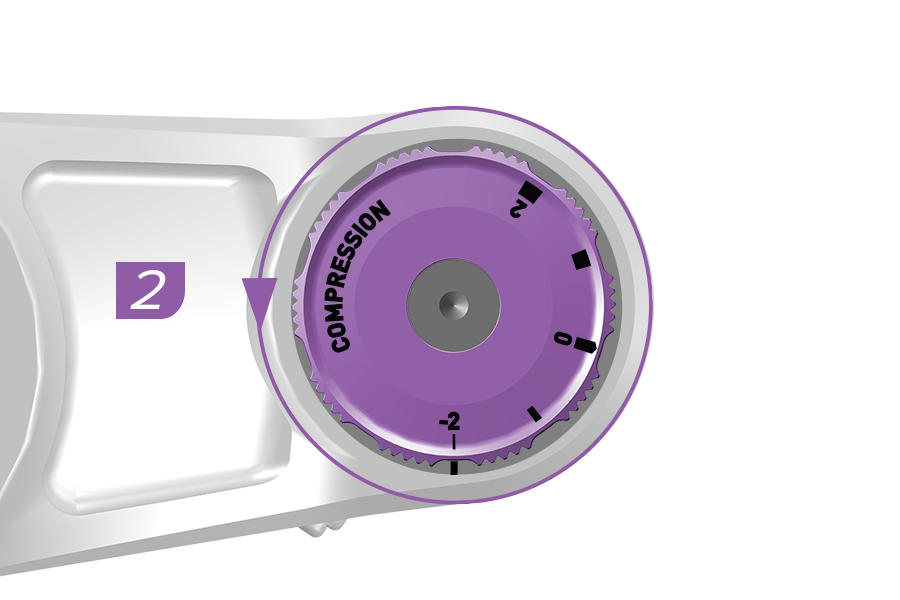
2. Adjust the compression damper(s) to the full OPEN setting(s).
Delta RC: Low Speed
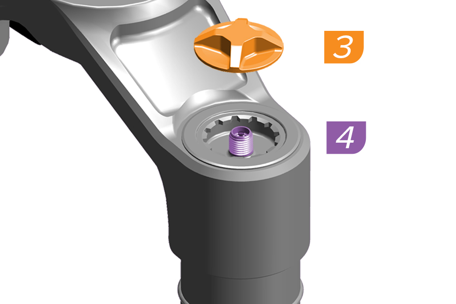
3. Remove the air spring cap.
4. Pressurize the Linear XL air spring to 50% of the recommended pressure on the fork air pressure decal or at trailhead.rockshox.com.
Remove the pump. Do not compress the suspension with the pump attached.
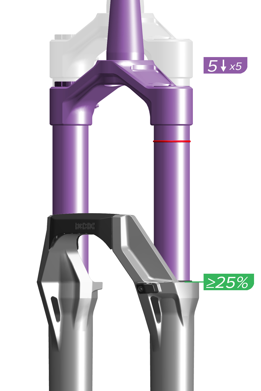
5. Slowly compress the fork (at least 3 seconds per compression) to 25% travel five times to equalize positive and negative air pressures.
Air pressure equalization ensures the air spring is accurately pressurized.
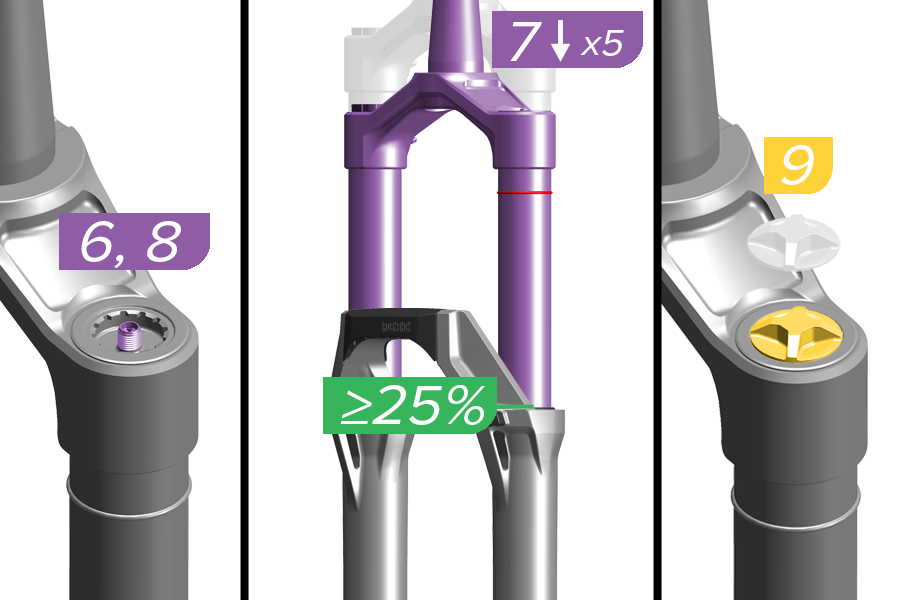
6. Pressurize the Linear XL air spring to 100% of the recommended pressure on the fork air pressure decal or at trailhead.rockshox.com. Remove the pump. Do not compress the suspension with the pump attached.
7. Slowly compress the fork (at least 3 seconds per compression) to 25% travel five times again to equalize positive and negative pressures.
8. Pressurize the Linear XL air spring once more to 100% of the recommended pressure on the fork air pressure decal or at trailhead.rockshox.com. Remove the pump.
9. Install the air cap.
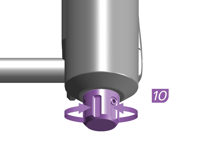
10. Adjust the rebound damper as recommended at RockShox Trailhead.
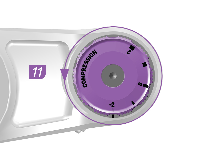
11. Adjust the compression adjuster to the OPEN setting to start.
12. Go for a ride to test your air spring and damping settings. The fork should achieve full travel at optimal air spring pressure.
Adjust air spring pressure and damper settings as preferred.
Bottomless Tokens can be removed or installed to fine-tune spring feel.
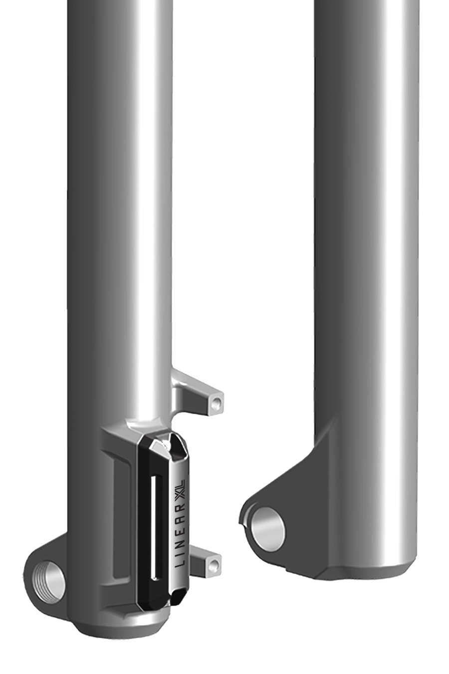
Optimal DebonAir+ and Linear XL air spring pressure results in small bump sensitivity, mid-stroke support, and the use of full travel. Setting DebonAir+ and Linear XL air spring pressure does not require the 'Set Sag' procedure.
BoXXer Gen D2 - 29" - Linear XL
BoXXer Gen D2 - 27.5" - DebonAir+
BoXXer Gen D1 - 29" and 27.5" - DebonAir+
After pressurizing a DebonAir+ or Linear XL fork to the recommended starting pressure, adjust the dampers:
All DebonAir+ and Linear XL fork models: Adjust the rebound damper to the recommended setting (RockShox Trailhead).
Charger 3 RC2, Charger 3.1 RC2, and Charger 3.2 RC2: Adjust the Low Speed Compression (LSC) damper setting to the middle setting.
Charger 3 RC and Charger 3.2 RC: Adjust Compression dampers to the OPEN setting.
Go for a test ride and make air pressure and damping adjustments as needed to achieve optimal performance.
Bottomless Tokens can be added or removed to further fine tune spring feel. Refer to the service manual for your fork for Bottomless Token quantities, and installation and removal procedures.
Getting Started: Front suspension air pressure recommendations listed on the back of your fork, and at RockShox Trailhead, are suggestions for initial spring setup.
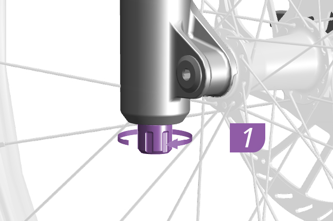
1. Adjust the rebound damper counterclockwise, to the full OPEN position.
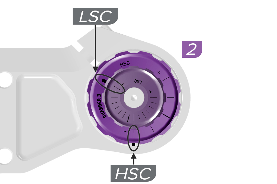
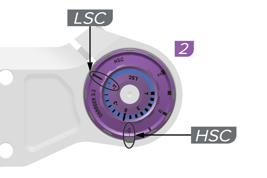
2. Adjust the compression damper(s) to the full OPEN setting(s).
Charger 3 RC2, Charger 3.2 RC2: Low Speed Compression and High Speed Compression
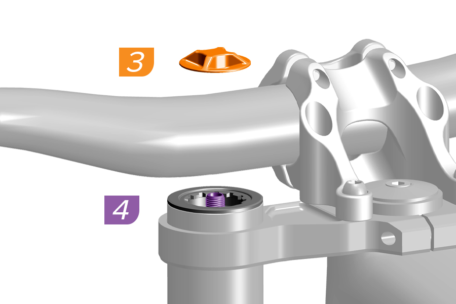
3. Remove the air spring cap.
4. Pressurize the DebonAir+ or Linear XL air spring to 50% of the recommended pressure on the fork air pressure decal or at RockShox Trailhead.
Remove the pump. Do not compress the suspension with the pump attached.
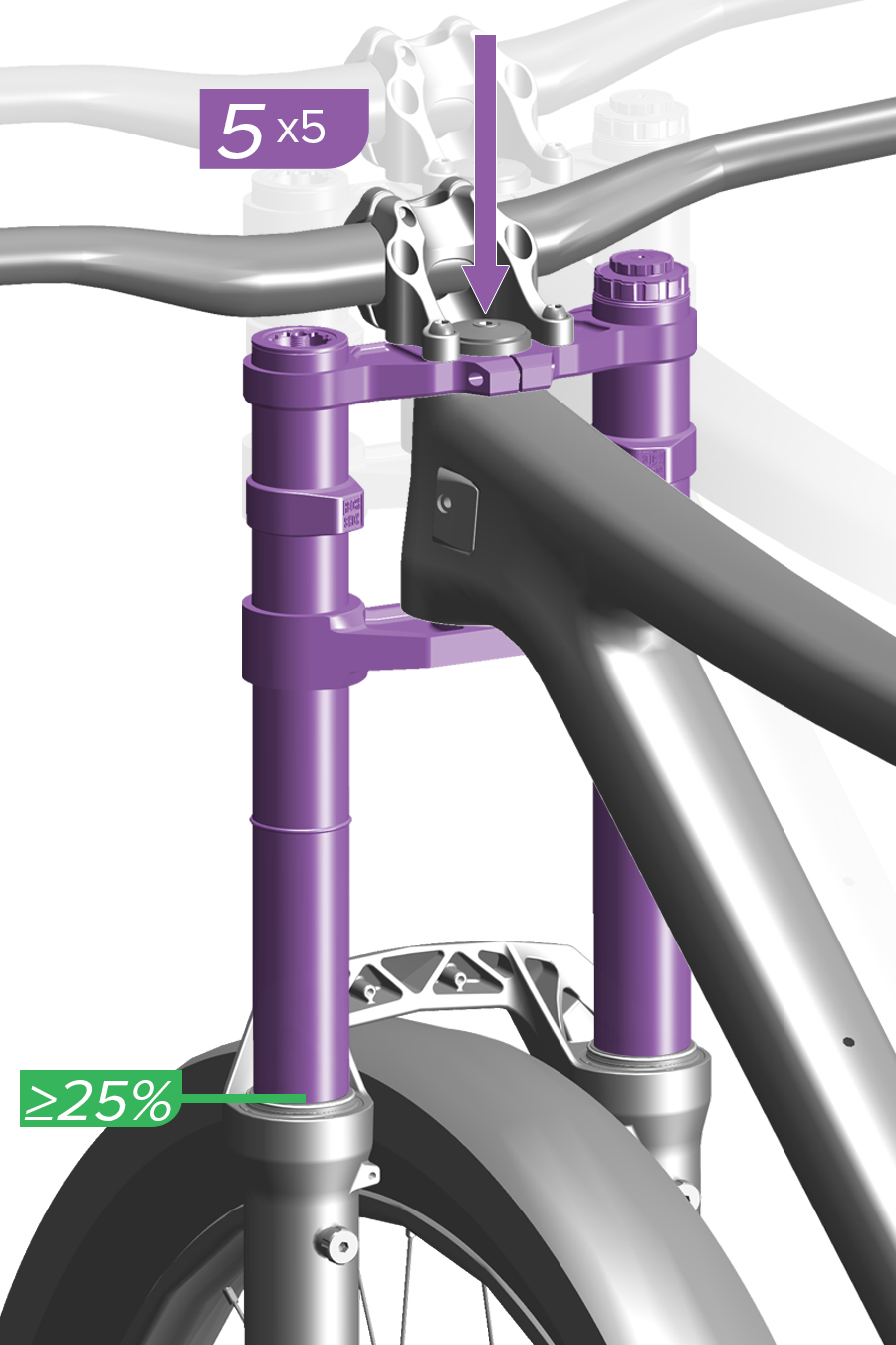
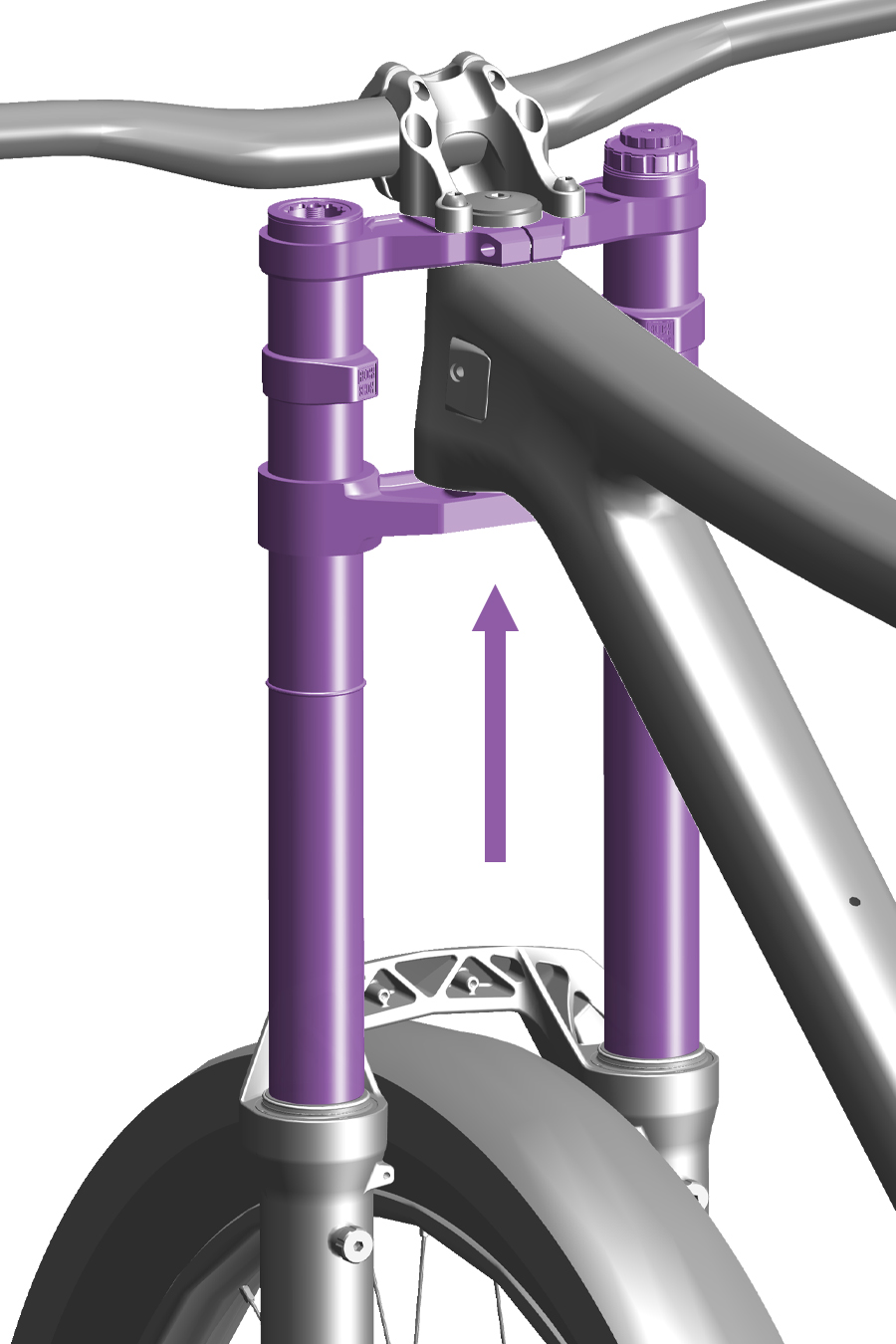
5. Slowly compress the fork (at least 3 seconds per compression) to 25% travel five times to equalize positive and negative air pressures.
Air pressure equalization ensures the air spring is accurately pressurized.
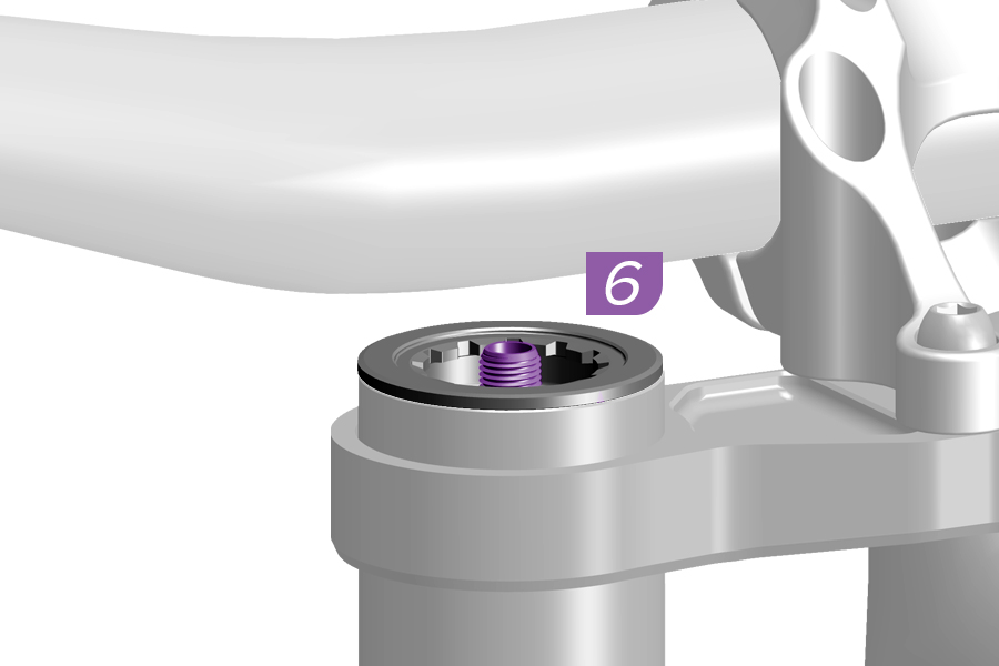
6. Pressurize the DebonAir+ or Linear XL air spring to 100% of the recommended pressure on the fork air pressure decal or at RockShox Trailhead.
Remove the pump. Do not compress the suspension with the pump attached.
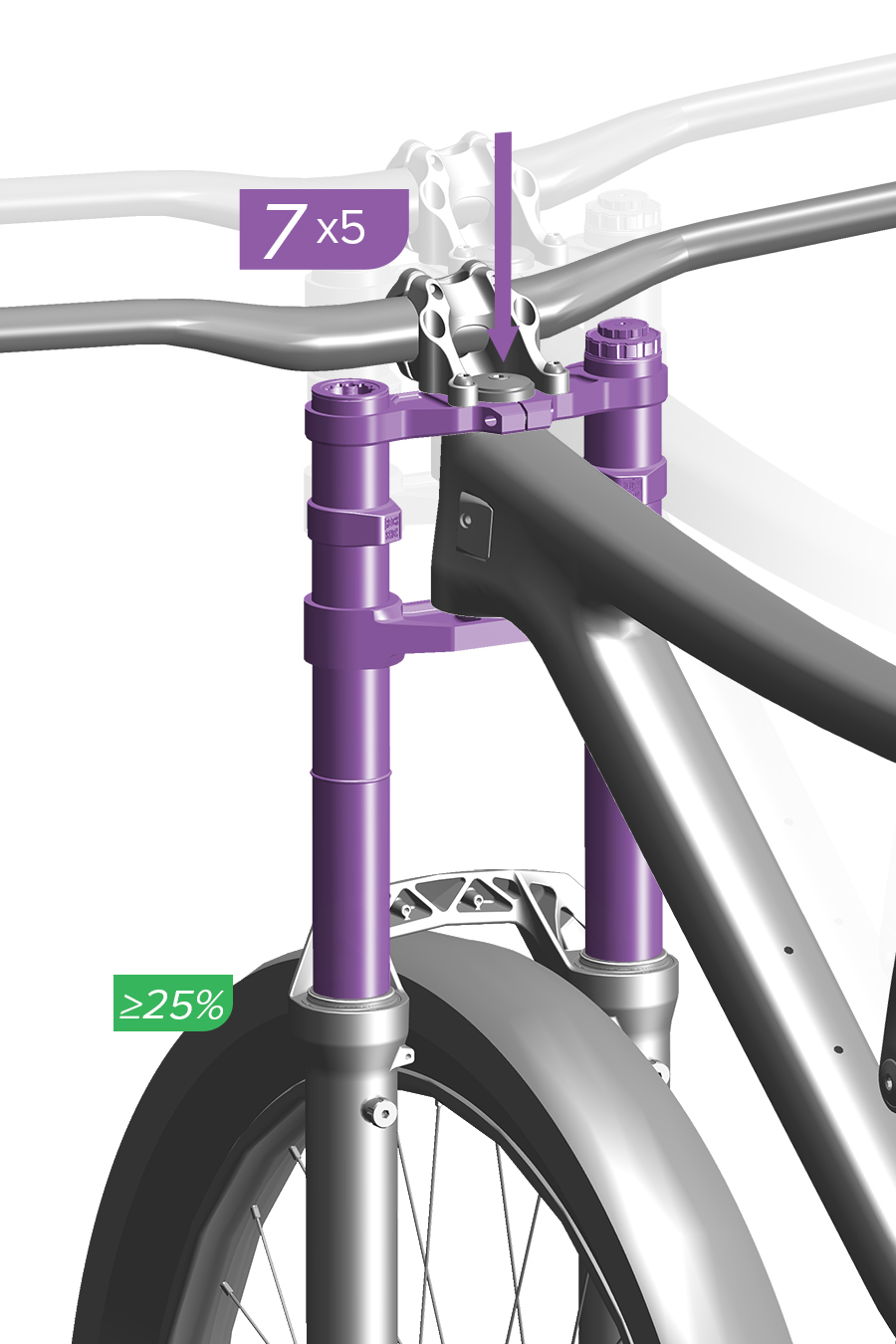
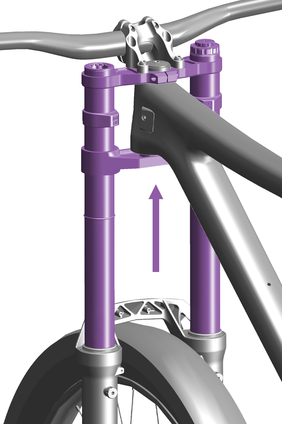
7. Slowly compress the fork (at least 3 seconds per compression) to 25% travel five times again to equalize positive and negative pressures.
Pressurize the DebonAir+ or Linear XL air spring once more to 100% of the recommended pressure on the fork air pressure decal or at RockShox Trailhead. Remove the pump.
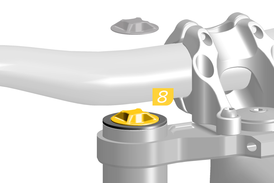
8. Install the air cap.
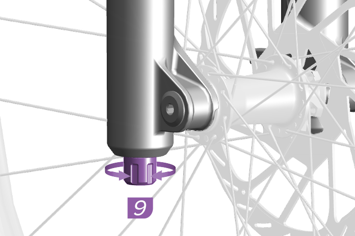
9. Adjust the rebound damper as recommended at RockShox Trailhead.
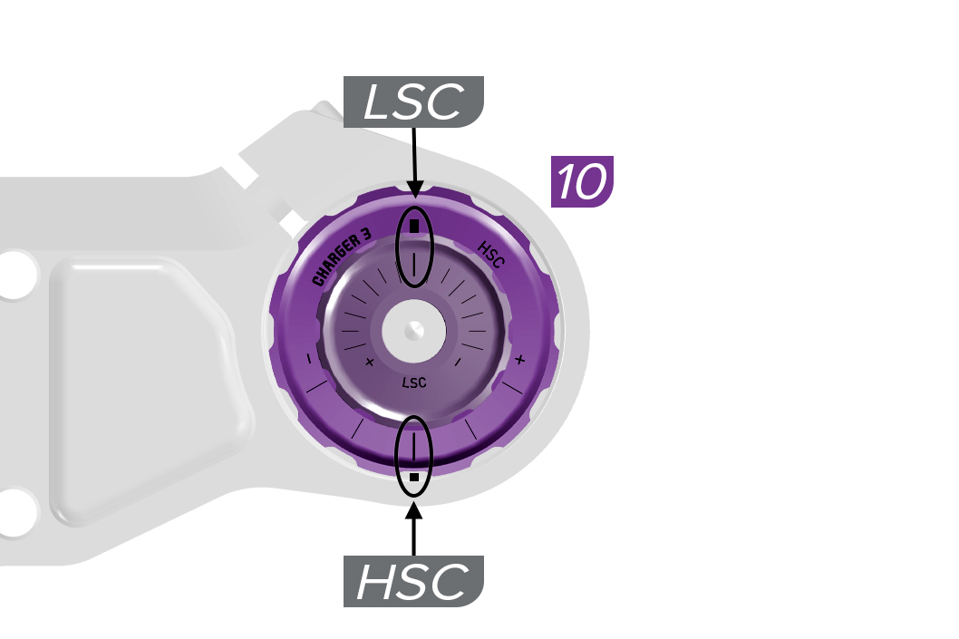
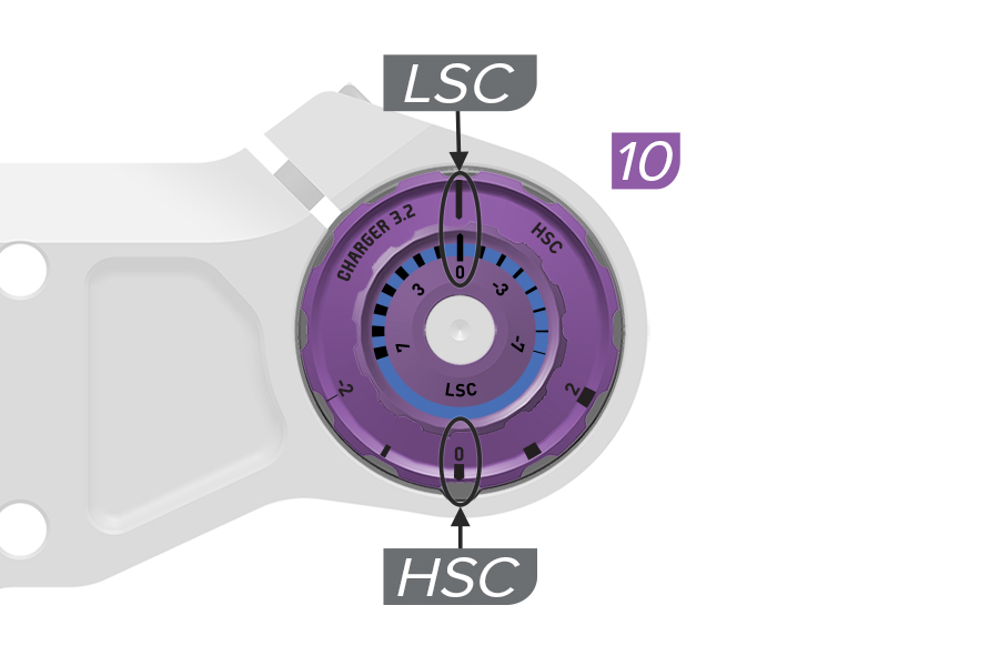
10. Charger 3 RC2, Charger 3.2 RC2: Adjust the Low Speed Compression (LSC) and High Speed Compression (HSC) damper adjusters to the MIDDLE settings to start.
11. Go for a ride to test your air spring and damping settings. The fork should achieve full travel at optimal air spring pressure.
Adjust air spring pressure and damper settings as preferred.
Bottomless Tokens can be removed or installed to fine-tune spring feel.
1. Adjust the rebound damper counterclockwise, to the full OPEN position.
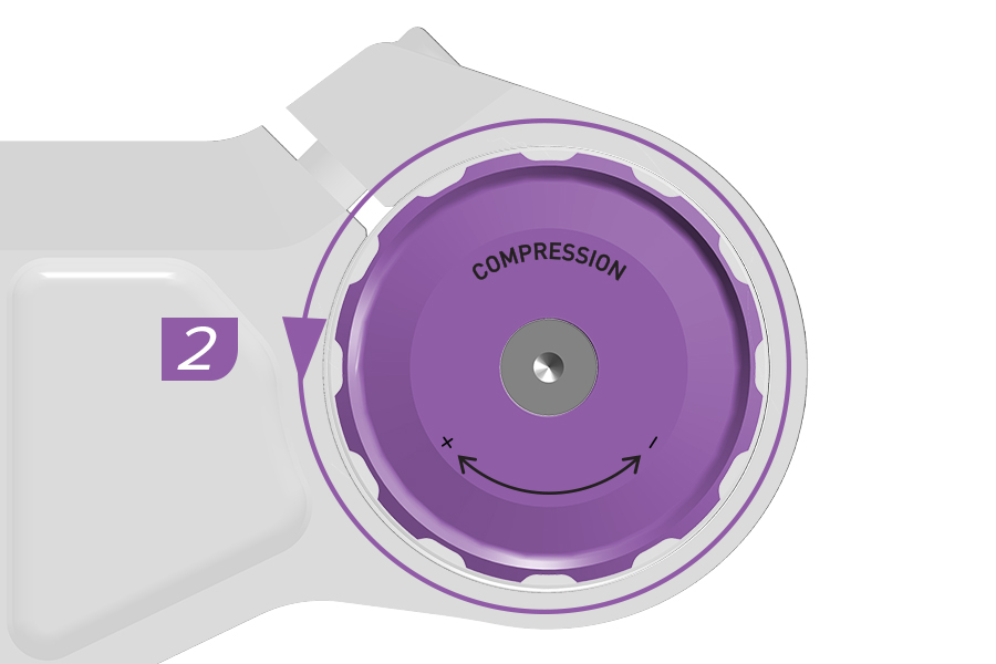
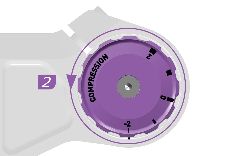
2. Adjust the compression damper(s) to the full OPEN setting(s).
Charger 3 RC, Charger 3.2 RC: Low Speed Compression
3. Remove the air spring cap.
4. Pressurize the DebonAir+ or Linear XL air spring to 50% of the recommended pressure on the fork air pressure decal or at RockShox Trailhead.
Remove the pump. Do not compress the suspension with the pump attached.
.2.jpg)
5. Slowly compress the fork (at least 3 seconds per compression) to 25% travel five times to equalize positive and negative air pressures.
Air pressure equalization ensures the air spring is accurately pressurized.
6. Pressurize the DebonAir+ or Linear XL air spring to 100% of the recommended pressure on the fork air pressure decal or at RockShox Trailhead.
Remove the pump. Do not compress the suspension with the pump attached.
.2.jpg)
7. Slowly compress the fork (at least 3 seconds per compression) to 25% travel five times again to equalize positive and negative pressures.
Pressurize the DebonAir+ or Linear XL air spring once more to 100% of the recommended pressure on the fork air pressure decal or at RockShox Trailhead. Remove the pump.
8. Install the air cap.
9. Adjust the rebound damper as recommended at RockShox Trailhead.
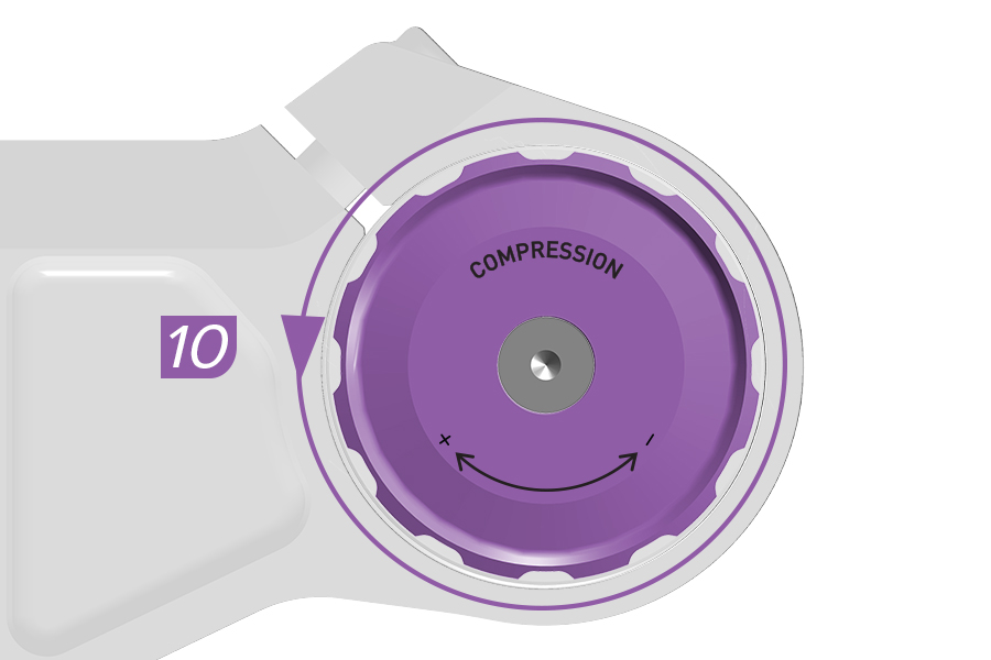
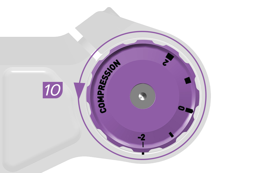
10. Charger 3 RC, Charger 3.2 RC: Adjust the compression adjuster to the OPEN setting to start.
11. Go for a ride to test your air spring and damping settings. The fork should achieve full travel at optimal air spring pressure.
Adjust air spring pressure and damper settings as preferred.
Bottomless Tokens can be removed or installed to fine-tune spring feel.
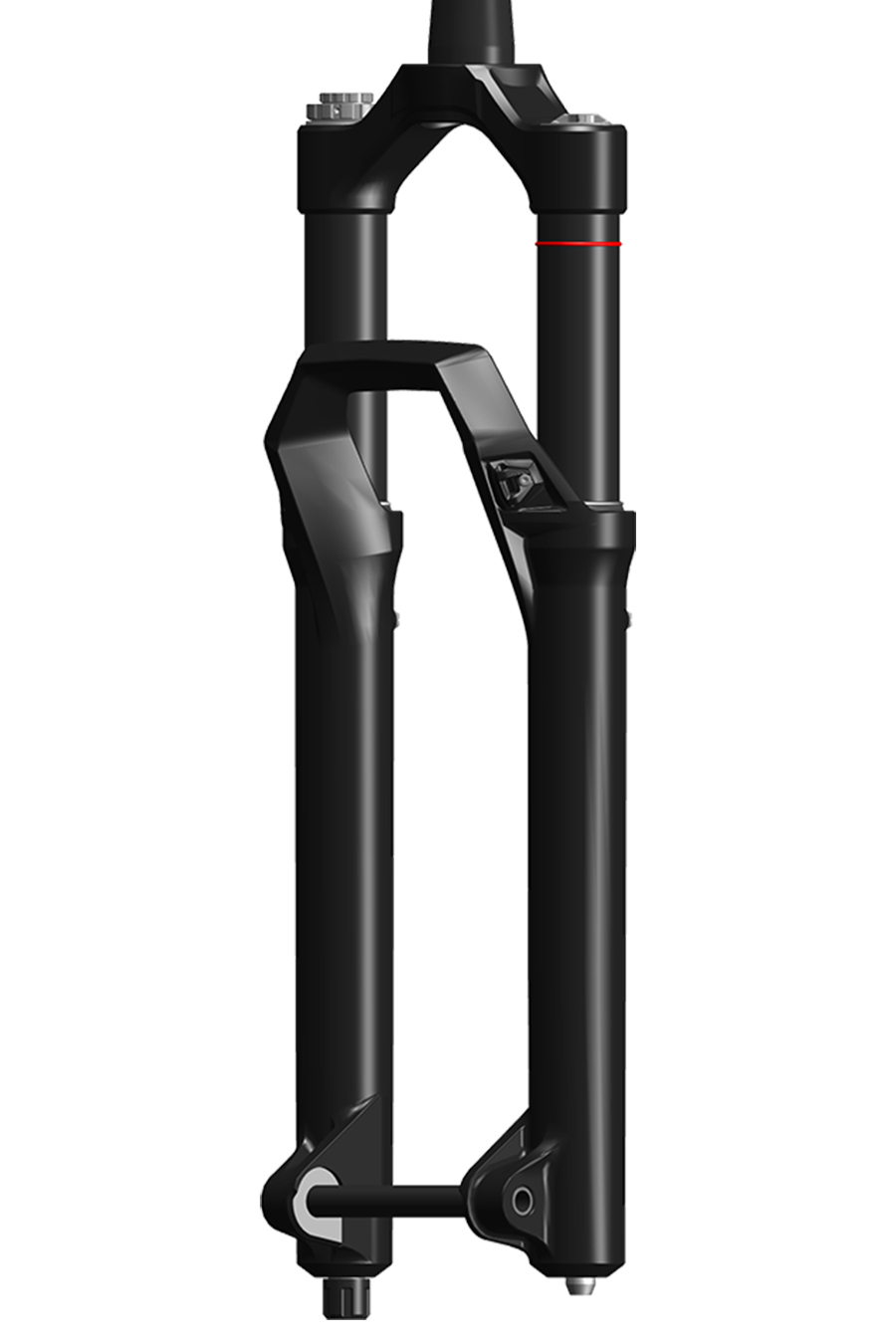
Optimal DebonAir+ air spring pressure results in small bump sensitivity, mid-stroke support, and the use of full travel. Setting DebonAir+ air spring pressure does not require the 'Set Sag' procedure.
After pressurizing a DebonAir+ fork to the recommended starting pressure, adjust the dampers:
All DebonAir+ fork models: Adjust the rebound damper to the recommended setting (RockShox Trailhead).
Charger 3.1 Flight Attendant: Set the fork Control Module to the OPEN position, and adjust the Low Speed Compression (LSC) damper setting to the middle setting.
Charger Flight Attendant: Set the fork Control Module to the OPEN position, and adjust the Low Speed Compression (LSC) damper setting to the softest setting.
Charger Race Day 2 Flight Attendant: Set the fork Control Module to the OPEN position.
Charger 3 RC2, Charger 3.1 RC2: Adjust the Low Speed Compression (LSC) damper setting to the middle setting.
Charger RC, Charger RL, Race Day 2, Rush RC, and Rush RL: Adjust Compression dampers to the OPEN setting.
All Flight Attendant Models: See the Flight Attendant User Manual for damper and Control Module procedures.
Go for a test ride and make air pressure and damping adjustments as needed to achieve optimal performance.
Bottomless Tokens can be added or removed to further fine tune spring feel. Refer to the service manual for your fork for Bottomless Token quantities, and installation and removal procedures.
Getting Started: Front suspension air pressure recommendations listed on the back of your fork, and at RockShox Trailhead, are suggestions for initial spring setup.
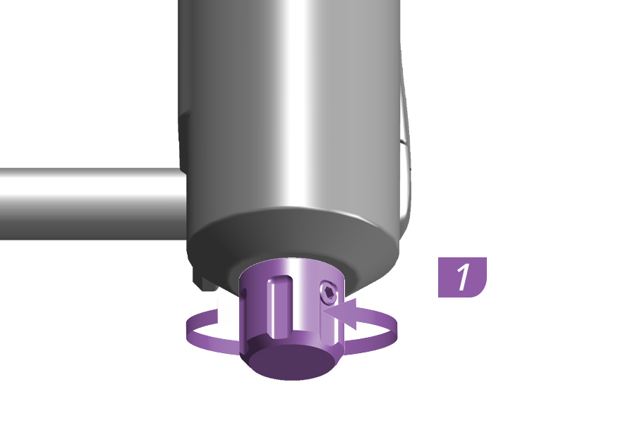
1. Adjust the rebound damper counterclockwise, to the full open position.
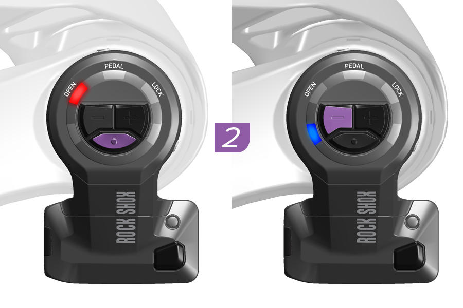
2. Set the fork Control Module to Manual Mode, set the suspension position to OPEN, and adjust Low Speed Compression damping to the lowest setting.
All Flight Attendant Models: See the Flight Attendant User Manual for damper and Control Module procedures.
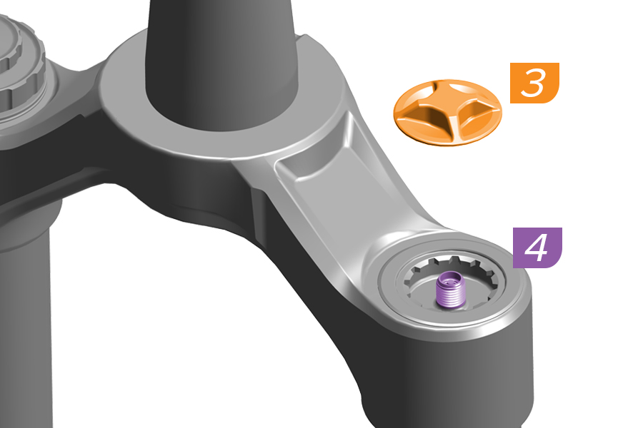
3. Remove the air spring cap.
4. Pressurize the DebonAir+ air spring to 50% of the recommended pressure on the fork air pressure decal or at RockShox Trailhead.
Remove the pump. Do not compress the suspension with the pump attached.
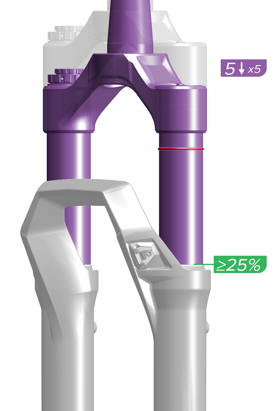
5. Slowly compress the fork (at least 3 seconds per compression) to 25% travel five times to equalize positive and negative air pressures. Air pressure equalization ensures the air spring is accurately pressurized.
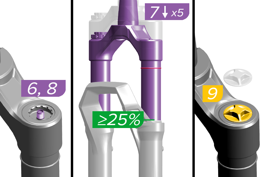
6. Pressurize the DebonAir+ air spring to 100% of the recommended pressure on the fork air pressure decal or at RockShox Trailhead. Remove the pump. Do not compress the suspension with the pump attached.
7. Slowly compress the fork (at least 3 seconds per compression) to 25% travel five times again to equalize positive and negative pressures.
8. Pressurize the DebonAir+ air spring once more to 100% of the recommended pressure on the fork air pressure decal or at RockShox Trailhead. Remove the pump.
9. Install the air cap.
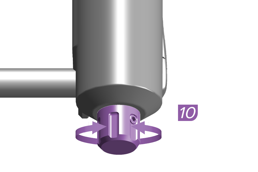
10. Adjust the rebound damper as recommended at RockShox Trailhead.
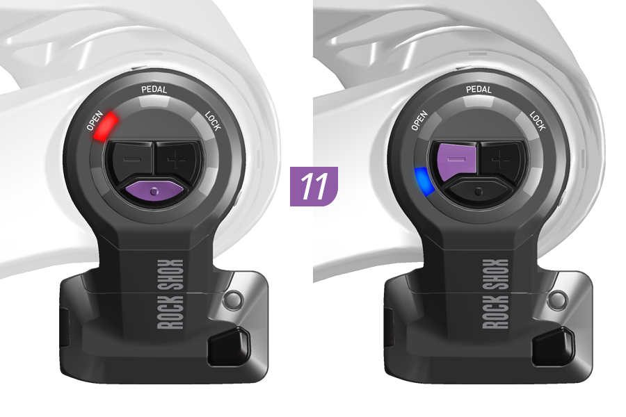
11. Set the fork Control Module to the OPEN position, and adjust the Low Speed Compression damper to the lowest setting to start. See the Flight Attendant User Manual for procedures.
12. Go for a ride to test your air spring and damping settings. The fork should achieve full travel at optimal air spring pressure.
Adjust air spring pressure and damper settings as preferred.
Bottomless Tokens can be removed or installed to fine-tune spring feel.
.jpg)
1. Adjust the rebound damper counterclockwise, to the full open position.
.jpg)
2. Set the fork Control Module to Manual Mode, set the suspension position to OPEN, and adjust Low Speed Compression damping to the lowest setting.
All Flight Attendant Models: See the Flight Attendant User Manual for damper and Control Module procedures.
.jpg)
3. Remove the air spring cap.
4. Pressurize the DebonAir+ air spring to 50% of the recommended pressure on the fork air pressure decal or at RockShox Trailhead
Remove the pump. Do not compress the suspension with the pump attached.
.jpg)
5. Slowly compress the fork (at least 3 seconds per compression) to 25% travel five times to equalize positive and negative air pressures.
Air pressure equalization ensures the air spring is accurately pressurized.
.jpg)
6. Pressurize the DebonAir+ air spring to 100% of the recommended pressure on the fork air pressure decal or at RockShox Trailhead. Remove the pump. Do not compress the suspension with the pump attached.
7. Slowly compress the fork (at least 3 seconds per compression) to 25% travel five times again to equalize positive and negative pressures.
8. Pressurize the DebonAir+ air spring once more to 100% of the recommended pressure on the fork air pressure decal or at RockShox Trailhead. Remove the pump.
9. Install the air cap.
.jpg)
10. Adjust the rebound damper as recommended at RockShox Trailhead.
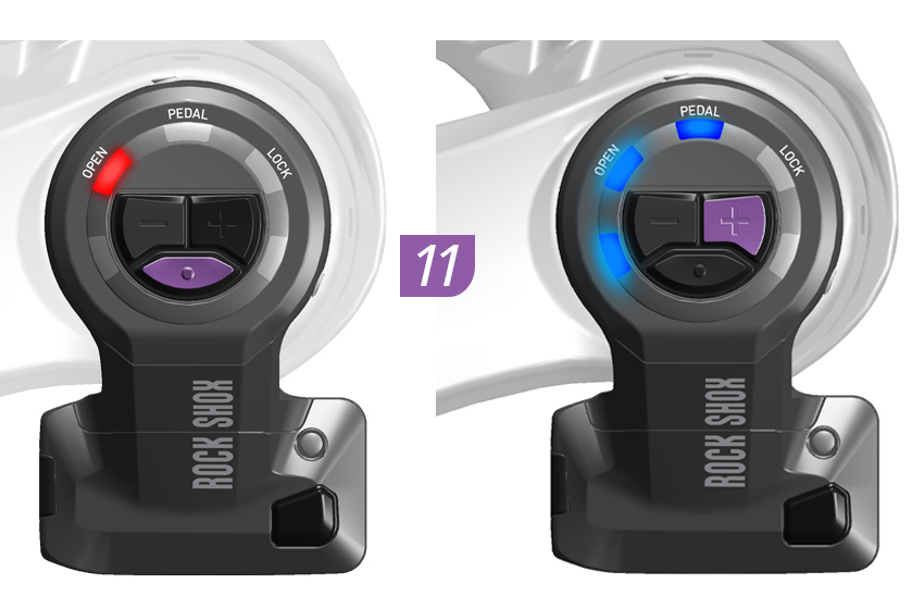
11. Set the fork Control Module to the OPEN position, and adjust the Low Speed Compression damper to the middle (5 or 6) setting to start.
See the Flight Attendant User Manual for procedures.
12. Go for a ride to test your air spring and damping settings. The fork should achieve full travel at optimal air spring pressure.
Adjust air spring pressure and damper settings as preferred.
Bottomless Tokens can be removed or installed to fine-tune spring feel.
1. Adjust the rebound damper counterclockwise, to the full open position.
2. Set the fork Control Module to Manual Mode, and set the suspension position to OPEN.
All Flight Attendant Models: See the Flight Attendant User Manual for damper and Control Module procedures.
3. Remove the air spring cap.
4. Pressurize the DebonAir+ air spring to 50% of the recommended pressure on the fork air pressure decal or at RockShox Trailhead
Remove the pump. Do not compress the suspension with the pump attached.
5. Slowly compress the fork (at least 3 seconds per compression) to 25% travel five times to equalize positive and negative air pressures.
Air pressure equalization ensures the air spring is accurately pressurized.
6. Pressurize the DebonAir+ air spring to 100% of the recommended pressure on the fork air pressure decal or at RockShox Trailhead. Remove the pump. Do not compress the suspension with the pump attached.
7. Slowly compress the fork (at least 3 seconds per compression) to 25% travel five times again to equalize positive and negative pressures.
8. Pressurize the DebonAir+ air spring once more to 100% of the recommended pressure on the fork air pressure decal or at RockShox Trailhead. Remove the pump.
9. Install the air cap.
10. Adjust the rebound damper as recommended at RockShox Trailhead.
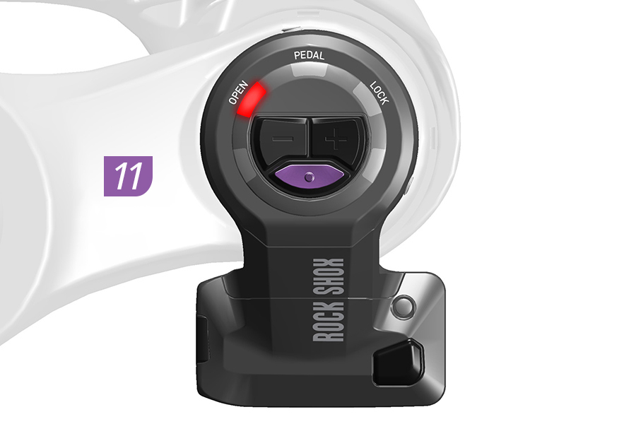
11. Set the fork Control Module to the OPEN position.
See the Flight Attendant User Manual for procedures.
12. Go for a ride to test your air spring and damping settings. The fork should achieve full travel at optimal air spring pressure.
Adjust air spring pressure and damper settings as preferred.
Bottomless Tokens can be removed or installed to fine-tune spring feel.
Various compression adjusters are pictured. Your product appearance may vary.
.jpg)
1. Adjust the rebound damper counterclockwise, to the full open position.
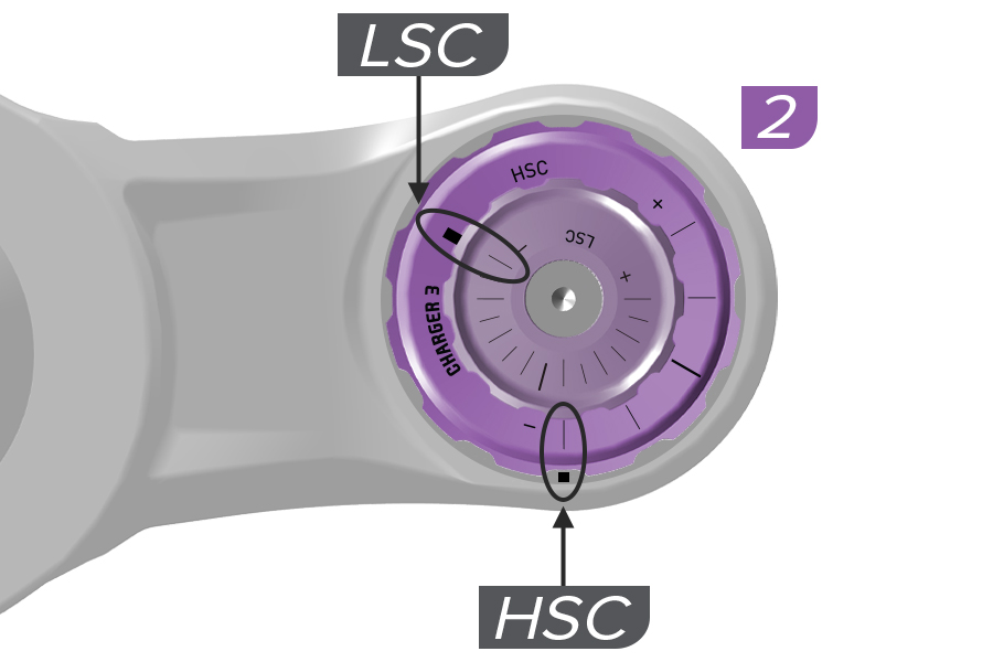
2. Adjust the compression damper(s) to the full open setting(s).
Charger 3 RC2, Charger 3.1 RC2: Low Speed and High Speed
.jpg)
3. Remove the air spring cap.
4. Pressurize the DebonAir+ air spring to 50% of the recommended pressure on the fork air pressure decal or at RockShox Trailhead. Remove the pump. Do not compress the suspension with the pump attached.
.jpg)
5. Slowly compress the fork (at least 3 seconds per compression) to 25% travel five times to equalize positive and negative air pressures.
Air pressure equalization ensures the air spring is accurately pressurized.
.jpg)
6. Pressurize the DebonAir+ air spring to 100% of the recommended pressure on the fork air pressure decal or at RockShox Trailhead. Remove the pump. Do not compress the suspension with the pump attached.
7. Slowly compress the fork (at least 3 seconds per compression) to 25% travel five times again to equalize positive and negative pressures.
8. Pressurize the DebonAir+ air spring once more to 100% of the recommended pressure on the fork air pressure decal or at RockShox Trailhead. Remove the pump.
9. Install the air cap.
.jpg)
10. Adjust the rebound damper as recommended at RockShox Trailhead.
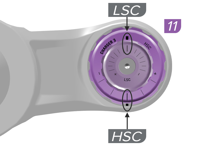
11. Charger 3 RC2, Charger 3.1 RC2: Adjust the Low speed (LSC) and High speed (HSC) compression damper adjusters to the middle settings to start.
12. Go for a ride to test your air spring and damping settings. The fork should achieve full travel at optimal air spring pressure.
Adjust air spring pressure and damper settings as preferred.
Bottomless Tokens can be removed or installed to fine-tune spring feel.
.jpg)
1. Adjust the rebound damper counterclockwise, to the full open position.
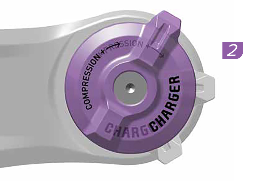
2. Adjust the compression damper adjuster counterclockwise to the full Open setting.
Charger RC: Low Speed Compression (LSC)
Charger RL: Open
Race Day 2: Open
.jpg)
3. Remove the air spring cap.
4. Pressurize the DebonAir+ air spring to 50% of the recommended pressure on the fork air pressure decal or at RockShox Trailhead. Remove the pump. Do not compress the suspension with the pump attached.
.jpg)
5. Slowly compress the fork (at least 3 seconds per compression) to 25% travel five times to equalize positive and negative air pressures.
Air pressure equalization ensures the air spring is accurately pressurized.
.jpg)
6. Pressurize the DebonAir+ air spring to 100% of the recommended pressure on the fork air pressure decal or at trailhead.rockshox.com. Remove the pump. Do not compress the suspension with the pump attached.
7. Slowly compress the fork (at least 3 seconds per compression) to 25% travel five times again to equalize positive and negative pressures.
8. Pressurize the DebonAir+ air spring once more to 100% of the recommended pressure on the fork air pressure decal or at RockShox Trailhead. Remove the pump.
9. Install the air cap.
.jpg)
10. Adjust the rebound damper as recommended at RockShox Trailhead.
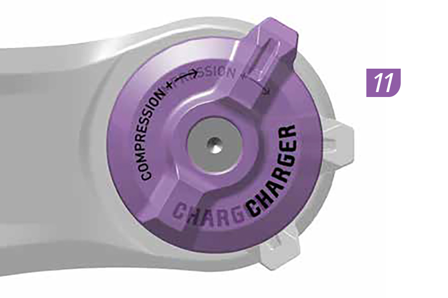
11. Adjust the compression adjuster to the OPEN setting to start.
12. Go for a ride to test your air spring and damping settings. The fork should achieve full travel at optimal air spring pressure.
Adjust air spring pressure and damper settings as preferred.
Bottomless Tokens can be removed or installed to fine-tune spring feel.
.jpg)
1. Adjust the rebound damper counterclockwise, to the full open position.
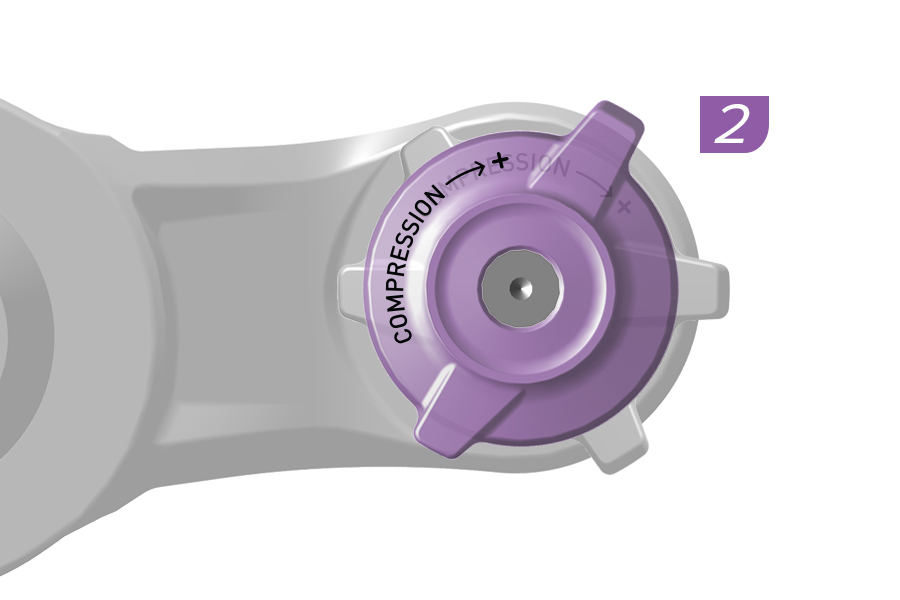
2. Adjust the compression damper(s) to the full open setting(s).
3. Remove the air spring cap.
4. Pressurize the DebonAir+ air spring to 50% of the recommended pressure on the fork air pressure decal or at RockShox Trailhead.
Remove the pump. Do not compress the suspension with the pump attached.
.jpg)
5. Slowly compress the fork (at least 3 seconds per compression) to 25% travel five times to equalize positive and negative air pressures.
Air pressure equalization ensures the air spring is accurately pressurized.
.jpg)
6. Pressurize the DebonAir+ air spring to 100% of the recommended pressure on the fork air pressure decal or at RockShox Trailhead. Remove the pump. Do not compress the suspension with the pump attached.
7. Slowly compress the fork (at least 3 seconds per compression) to 25% travel five times again to equalize positive and negative pressures.
8. Pressurize the DebonAir+ air spring once more to 100% of the recommended pressure on the fork air pressure decal or at RockShox Trailhead. Remove the pump.
9. Install the air cap.
.jpg)
10. Adjust the rebound damper as recommended at RockShox Trailhead.
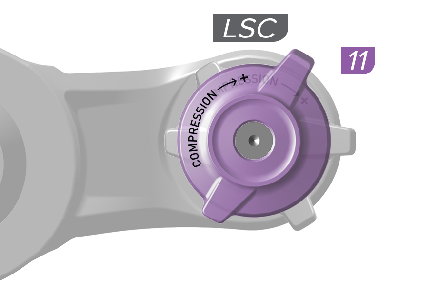
11. Adjust the compression adjuster to the open setting to start.
12. Go for a ride to test your air spring and damping settings. The fork should achieve full travel at optimal air spring pressure.
Adjust air spring pressure and damper settings as preferred.
Bottomless Tokens can be removed or installed to fine-tune spring feel.
1. Adjust the rebound damper counterclockwise, to the full open position.
2. Adjust the compression dampers to the full open setting.
Charger 3 RC2: Low Speed Compression (LSC) and High Speed Compression (HSC)
3. Remove the air spring cap.
4. Pressurize the DebonAir+ air spring to 50% of the recommended pressure on the fork air pressure decal or at RockShox Trailhead.
Remove the pump. Do not compress the suspension with the pump attached.
5. Slowly compress the fork (at least 3 seconds per compression) to 25% travel five times to equalize positive and negative air pressures. Air pressure equalization ensures the air spring is accurately pressurized.
6. Pressurize the DebonAir+ air spring to 100% of the recommended pressure on the fork air pressure decal or at RockShox Trailhead. Remove the pump. Do not compress the suspension with the pump attached.
.1.jpg)
7. Slowly compress the fork (at least 3 seconds per compression) to 25% travel five times again to equalize positive and negative pressures.
Pressurize the DebonAir+ air spring once more to 100% of the recommended pressure on the fork air pressure decal or at RockShox Trailhead. Remove the pump.
8. Install the air cap.
9. Adjust the rebound damper as recommended at RockShox Trailhead.
10. Charger 3 RC2: Adjust the Low speed (LSC) and High speed (HSC) compression damper adjusters to the middle settings to start.
11. Go for a ride to test your air spring and damping settings. The fork should achieve full travel at optimal air spring pressure.
Adjust air spring pressure and damper settings as preferred.
Bottomless Tokens can be removed or installed to fine-tune spring feel.
.jpg)
1. Adjust the rebound damper counterclockwise, to the full open position.
2. Adjust the compression damper to the full open setting.
Charger RC: Low Speed Compression (LSC)
.jpg)
3. Remove the air spring cap.
4. Pressurize the DebonAir+ air spring to 50% of the recommended pressure on the fork air pressure decal or at RockShox Trailhead.
Remove the pump. Do not compress the suspension with the pump attached.
.3.jpg)
5. Slowly compress the fork (at least 3 seconds per compression) to 25% travel five times to equalize positive and negative air pressures.
Air pressure equalization ensures the air spring is accurately pressurized.
.jpg)
6. Pressurize the DebonAir+ air spring to 100% of the recommended pressure on the fork air pressure decal or at RockShox Trailhead.
Remove the pump. Do not compress the suspension with the pump attached.
7. Slowly compress the fork (at least 3 seconds per compression) to 25% travel five times again to equalize positive and negative pressures.
Pressurize the DebonAir+ air spring once more to 100% of the recommended pressure on the fork air pressure decal or at RockShox Trailhead. Remove the pump.
.jpg)
8. Install the air cap.
.jpg)
9. Adjust the rebound damper as recommended at RockShox Trailhead.
10. Charger 3 RC: Adjust the compression adjuster to the open setting to start.
11. Go for a ride to test your air spring and damping settings. The fork should achieve full travel at optimal air spring pressure.
Adjust air spring pressure and damper settings as preferred.
Bottomless Tokens can be removed or installed to fine-tune spring feel.
If you have a DebonAir+ fork refer to Set Air Spring Pressure - DebonAir+ for optimal performance.
Suspension sag is the percentage of full travel that the suspension compresses when the rider, including gear, is on the bicycle in a normal riding position. Setting the correct sag allows the suspension to perform effectively. Optimal suspension sag is the result of setting the proper suspension spring rate.
More sag (20% - 30%) increases bump sensitivity and suspension movement. More bump sensitivity results in a smoother ride and is typically preferred on longer travel bicycles.
Less sag (10% - 20%) decreases bump sensitivity and suspension movement. Less bump sensitivity results in a more firm, efficient ride and is typically preferred on shorter travel bicycles.
Too much sag is an indicator that the spring rate should be increased by either increasing air spring pressure or changing the coil spring to a stiffer spring.
Air spring suspension forks: Air pressure, after sag is set, may differ from the recommended starting air spring pressure printed on your fork based on travel, bicycle geometry, and rider preference.
Important: Sag must be set before making any damping adjustments.
Sag Gradients: Many RockShox forks and rear shocks include sag percentage gradients and a sag o-ring on one upper tube, or the rear shock body or shaft. If a sag o-ring is not on your suspension, install a plastic cable tie around the upper tube, shock body or shock shaft, just tight enough so it does not move. Remove the cable tie before riding.
If your fork or rear shock does not have sag percentage gradients, to calculate target sag, multiply the target sag percentage by the total amount of suspension travel. Use a ruler to measure the length of exposed upper tube, damper body or shock shaft above the wiper seal to the sag o-ring.
If your suspension's travel is unknown, before sag is measured, fully compress the suspension to bottom out. Release and use a ruler to measure the length of exposed upper tube, damper body, or shock shaft below the sag o-ring or stopping point of the wiper seal.
Getting started: Front suspension air pressure recommendations listed on the back of your fork, and at RockShox Trailhead, are suggestions for initial spring setup. Front suspension coil springs are available in a number of spring rates ranging from soft to extra firm. Refer to the appropriate model year RockShox Front Suspension Oil, Air, Coil, Token, and Specification document for coil spring recommendations based on rider weight.
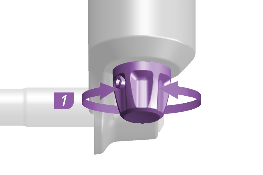
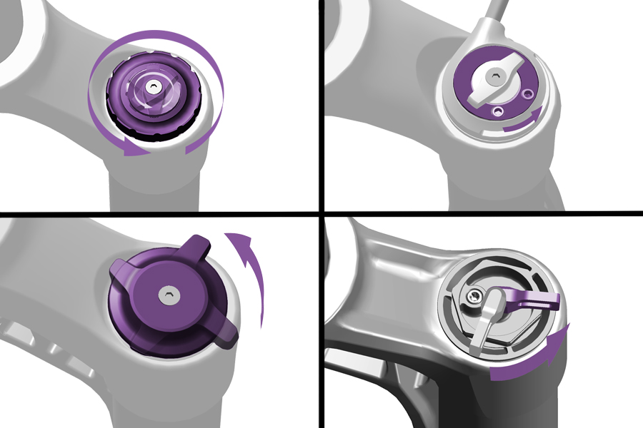
Before setting sag, set all dampers (rebound and compression) to the full open positions.
1. Rotate each adjuster knob counterclockwise until they stop.
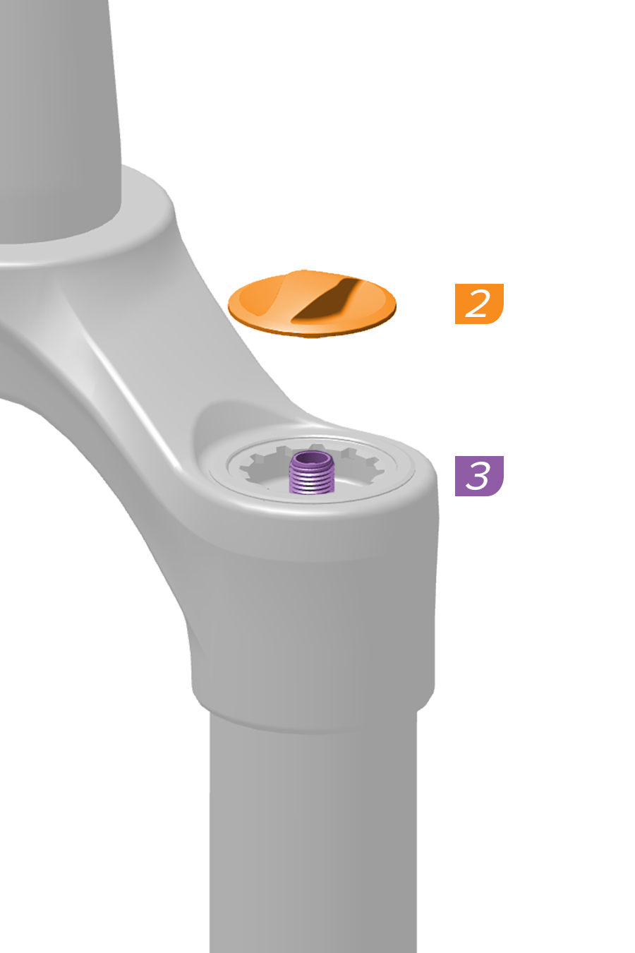
2. Remove the air cap.
3. Pressurize the air spring to the recommended starting air pressure on the fork decal or RockShox Trailhead. For Dual Position Air forks, pressurize the fork in the full travel position. Remove the pump.
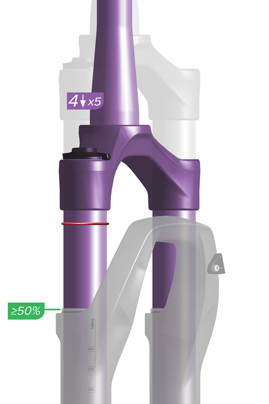
4. Solo Air and DebonAir only: Compress the fork through at least 50% of travel 5 times to equalize positive and negative air pressures. Air pressure equalization ensures the positive air spring is accurately pressurized.
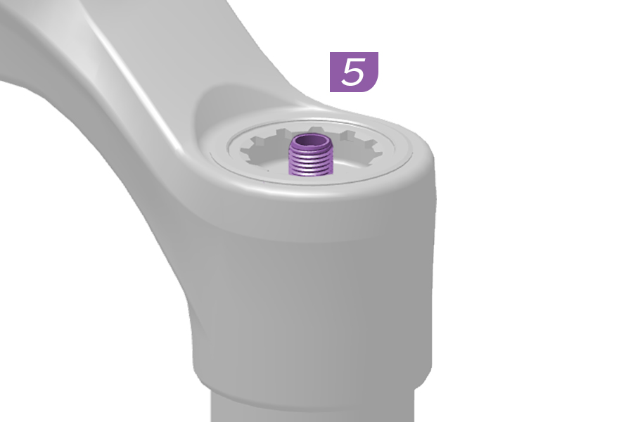
5. Pressurize the air spring to the same recommended starting pressure once more. Remove the pump.
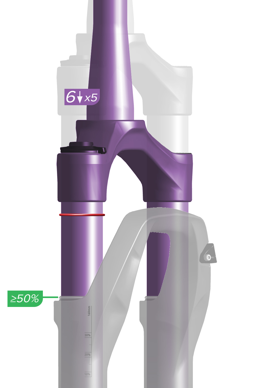
6. Solo Air and DebonAir only: Compress the fork through at least 50% of travel 5 more times to equalize positive and negative air pressures.
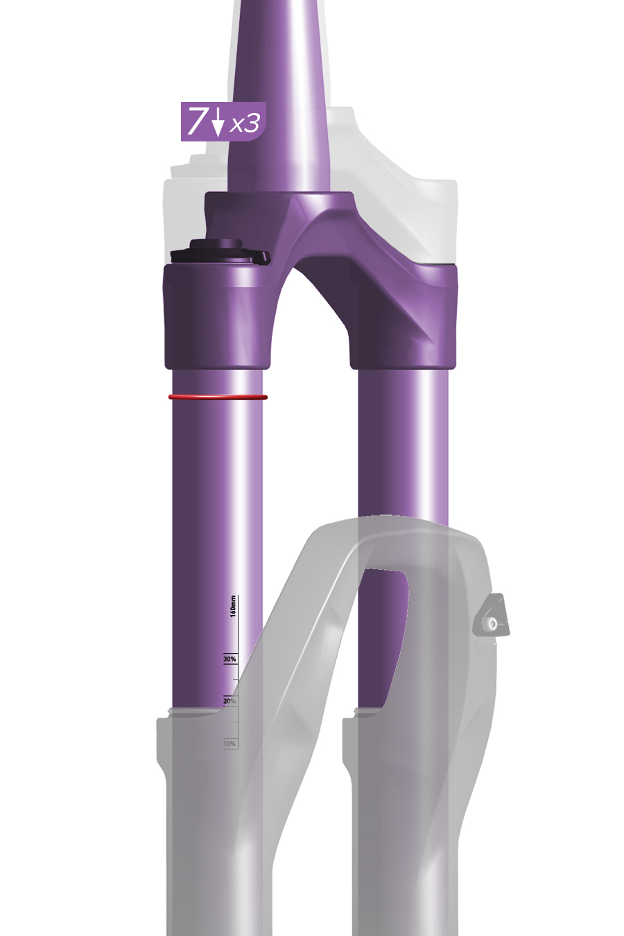
7. With riding gear on, and an assistant holding the bike, stand on the pedals and compress the fork three times. Then sit or stand in your normal riding position.
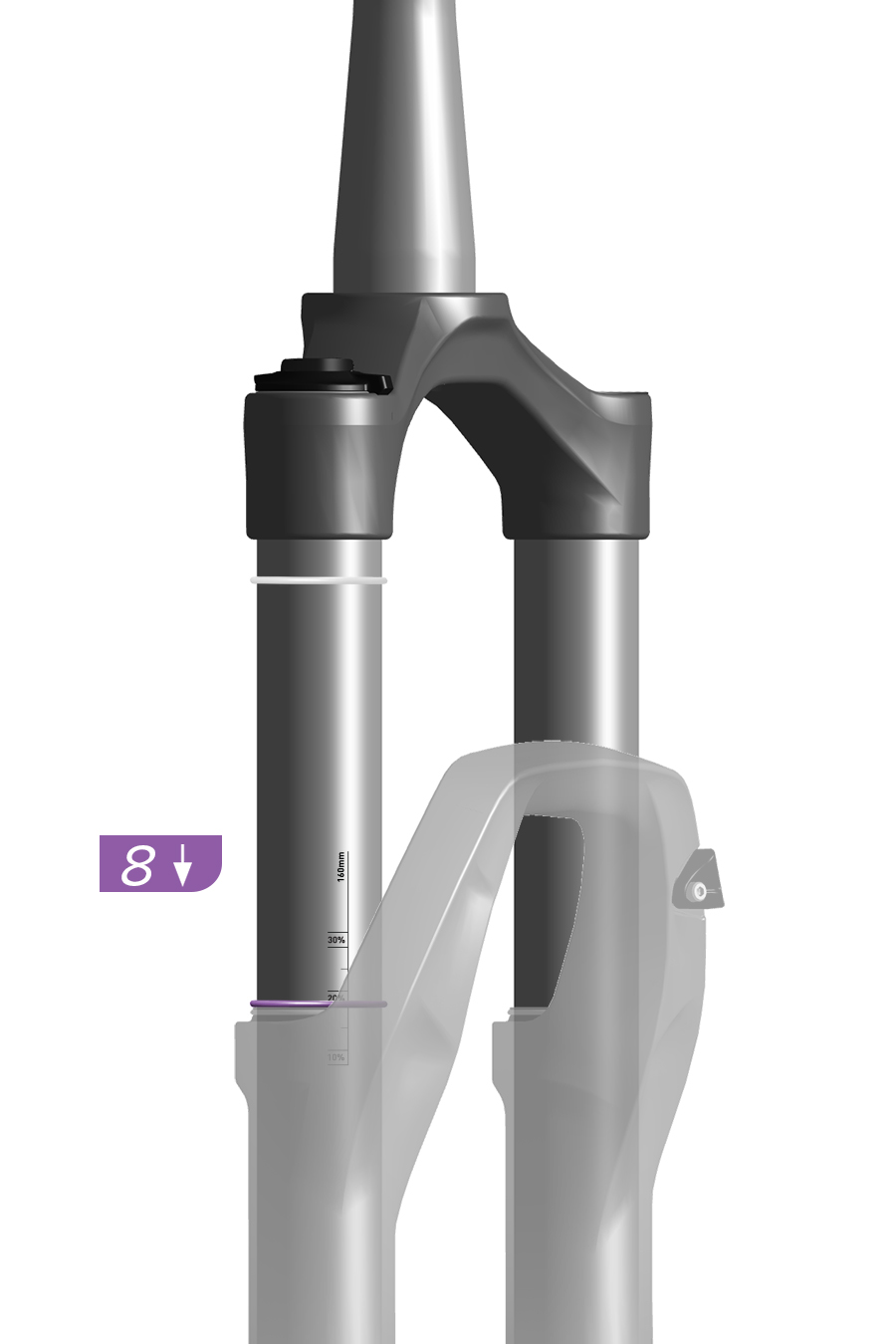
8. Have your assistant slide the sag o-ring down to the top of the dust wiper seal.
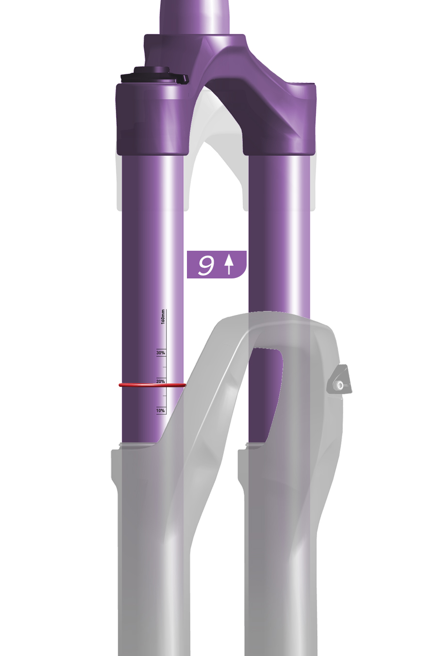
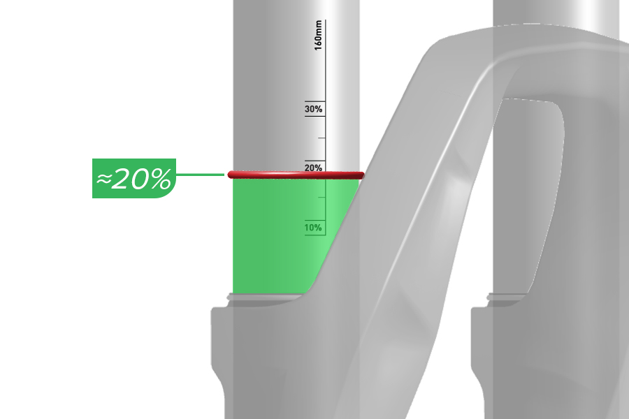
9. Gently step off the bicycle without compressing the fork any further. Note the sag percentage where the o-ring stopped.
If your fork does not have sag percentage gradients, to calculate target sag, multiply the target sag percentage by the total amount of suspension travel. Use a ruler to measure the length of exposed upper tube above the wiper seal to the sag o-ring.
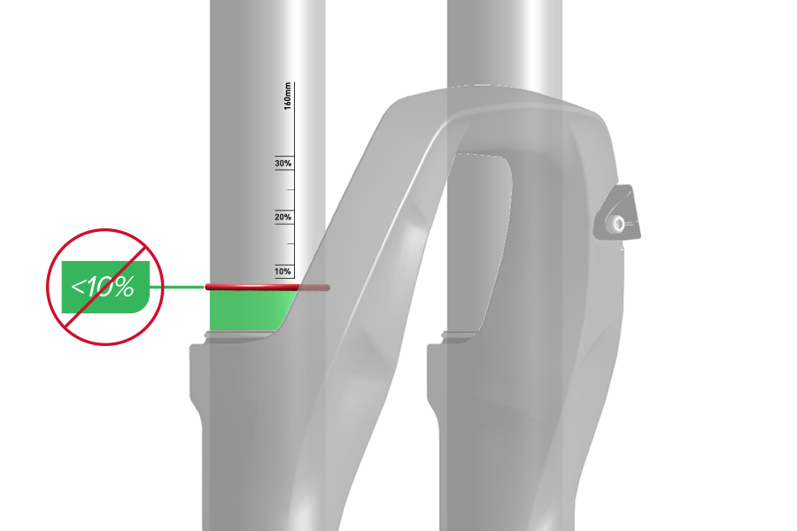
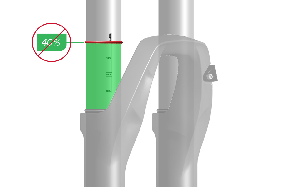
If your target sag percentage is not achieved, air pressure must be adjusted.
Increase air pressure to decrease sag, and decrease air pressure to increase sag.
Repeat the sag process until your target sag percentage is achieved.
Rudy XPLR: Target sag is 5%.
Sag is the amount (percentage) the suspension compresses when the rider, including riding gear, is seated on the bicycle in the riding position.
Setting proper sag allows the wheels to maintain traction without using too much travel reserved for shock absorption.
More sag increases small bump sensitivity, while less sag decreases small bump sensitivity.
Check spring sag and replace the coil spring if necessary, before making any other tuning adjustments.
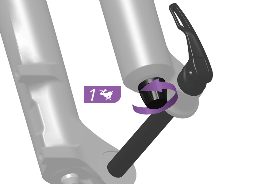
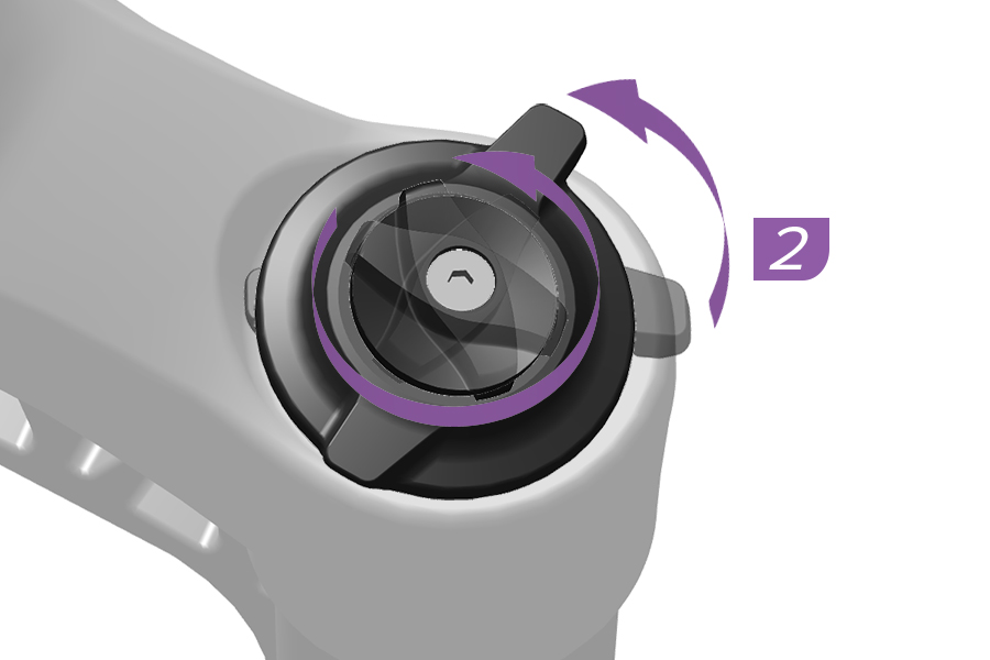
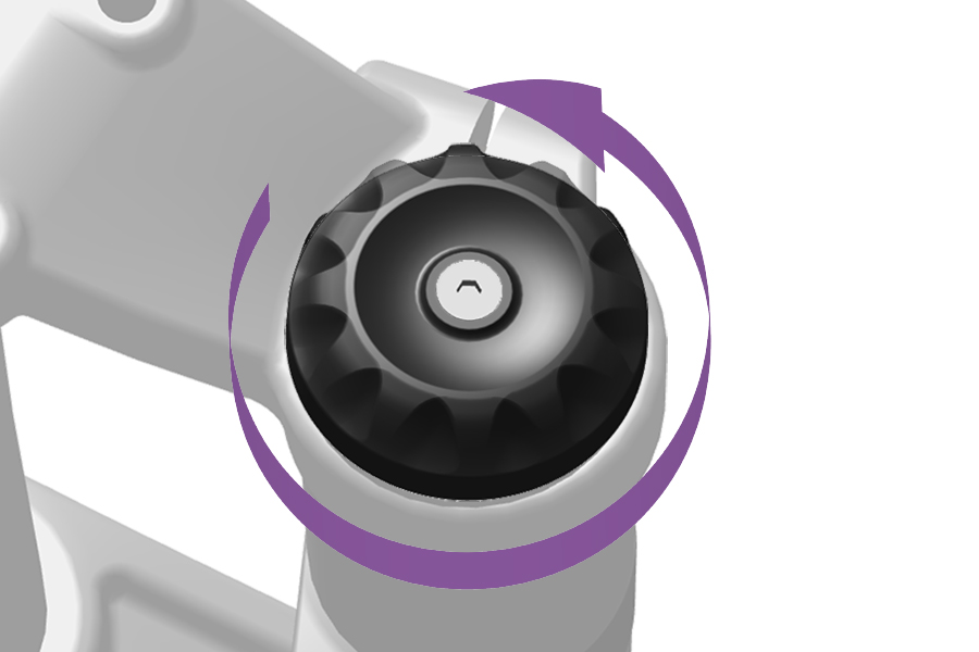
1-2. Before setting sag, set the dampers to the full open positions. Rotate the adjusters counterclockwise until they stop.
Remote: Set the compression damper to the open position.
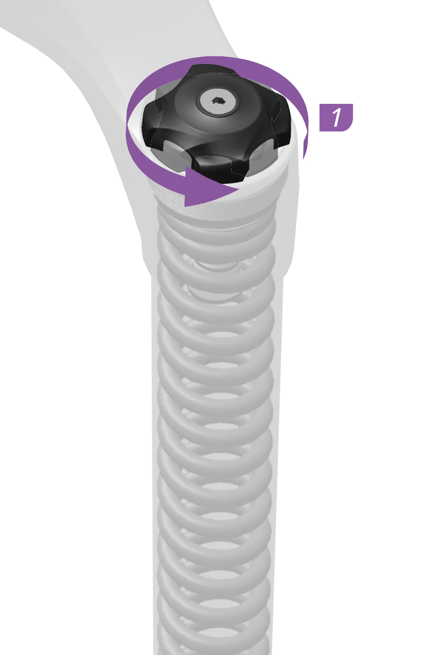
1. Turn the preload adjuster knob counterclockwise until it stops.
This is the least amount of spring preload, or the softest setting.
Dual Position Coil: Does not include a preload adjuster. Set the spring to full travel.
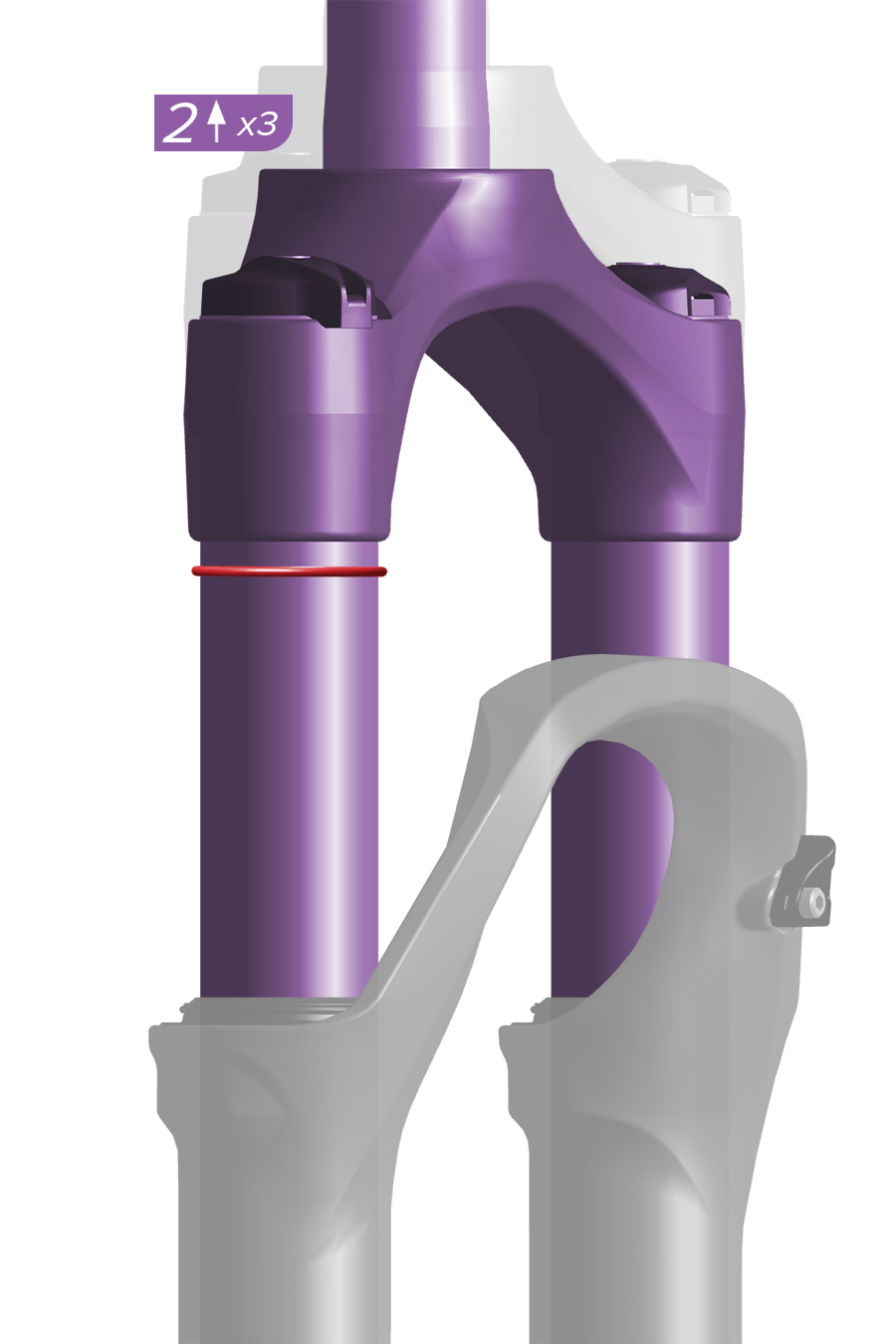
2. With riding gear on, and an assistant holding the bike, stand on the pedals, and compress the fork three times. Then sit or stand in your normal riding position.
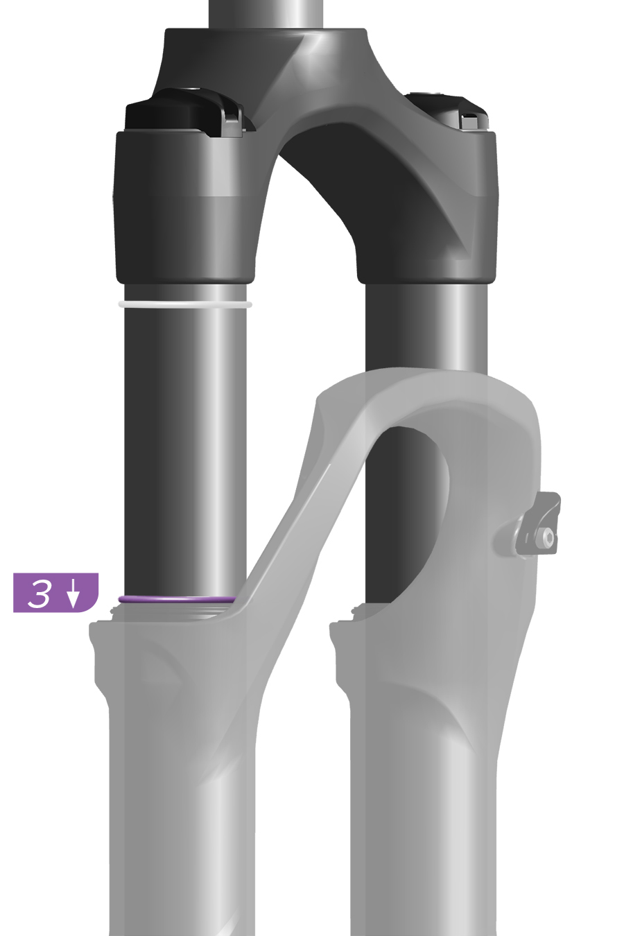
3. Have your assistant slide the sag o-ring down to the top of the dust seal.
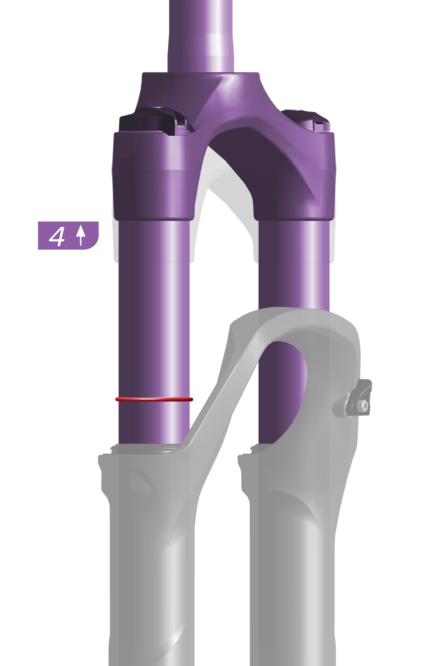
4. Gently step off the bicycle without compressing the fork any further.
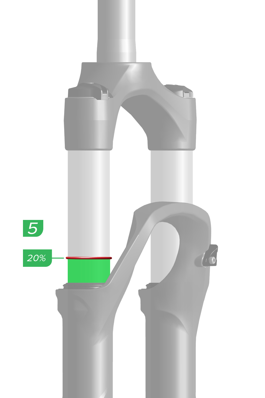
5. Note the sag percentage where the o-ring stopped.
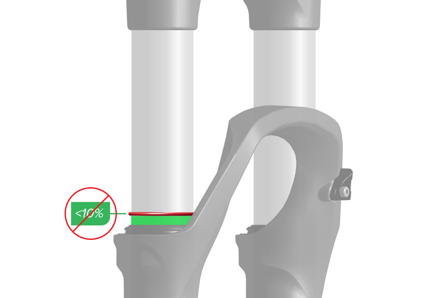
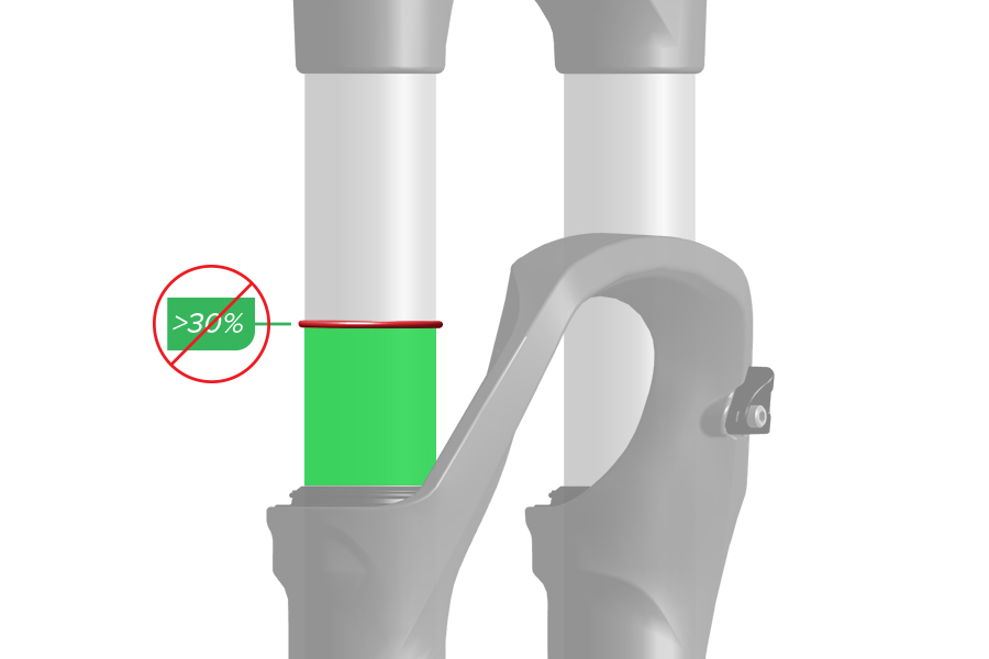
If your target sag percentage is not achieved, spring preload adjustment and/or coil spring replacement must be performed.
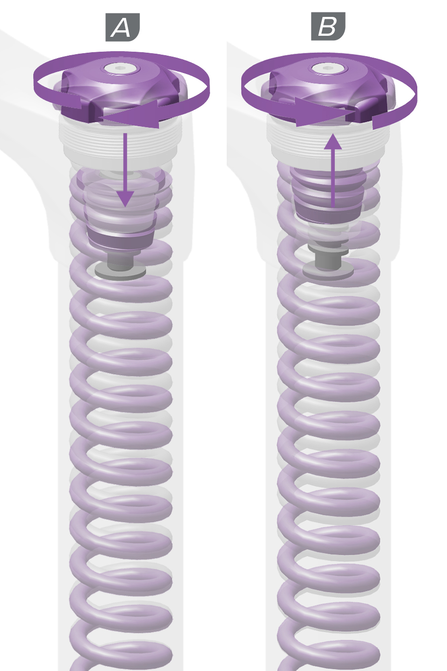
External spring preload adjustment compresses or decompresses the spring without initiating travel.
A. Turn the preload adjuster knob clockwise to increase spring preload and decrease sag.
B. Turn the preload adjuster knob counterclockwise to decrease spring preload and increase sag.
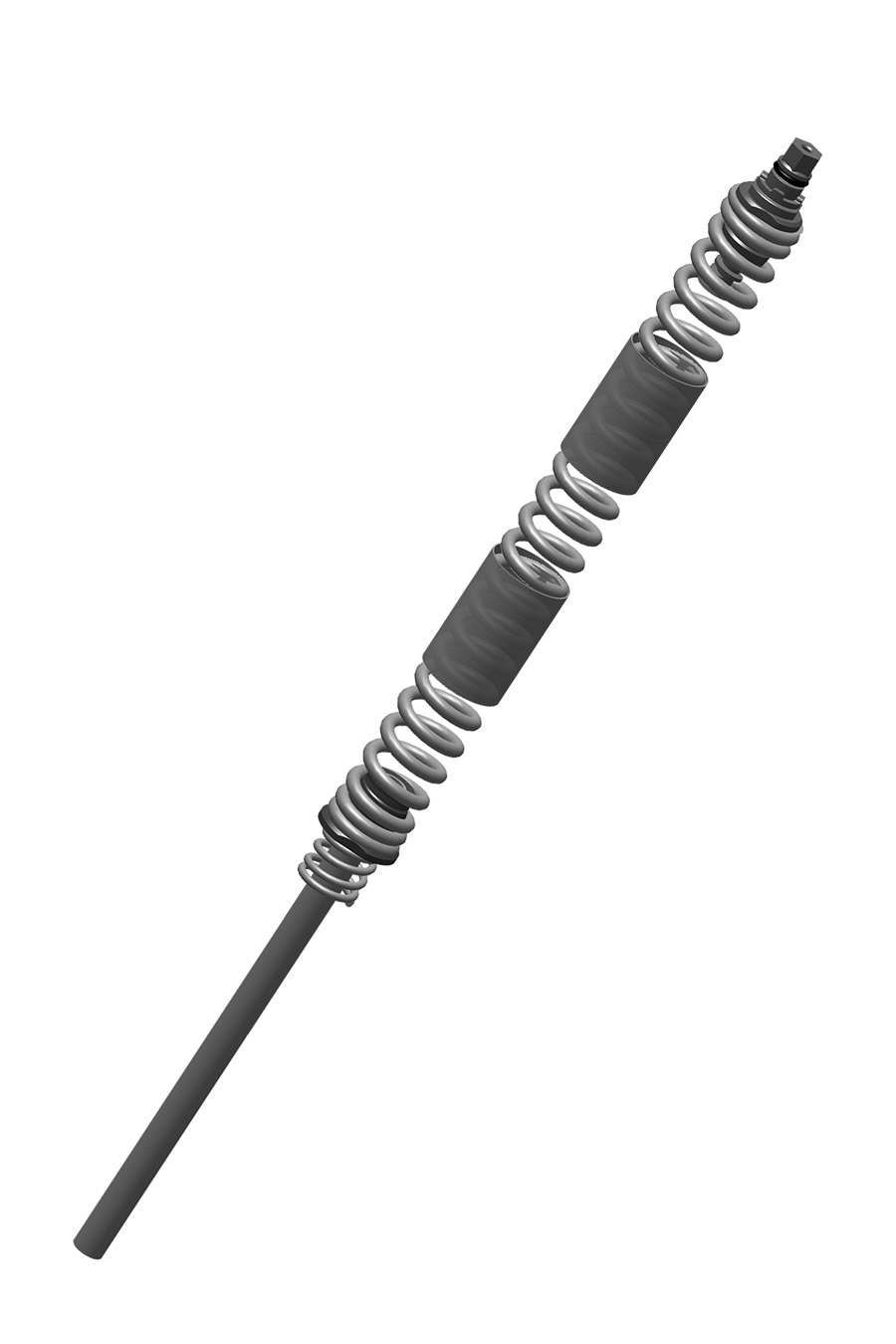
Spring preload adjustment can be used to fine tune sag, but preload does not change spring rate and is not a substitute for the proper coil spring weight.
If the proper sag cannot be achieved after external preload adjustment, the coil spring assembly must be replaced with a softer or firmer spring.
To increase sag, install a softer coil spring assembly.
To decrease sag, install a firmer coil spring assembly.
Repeat the sag process until your target sag percentage is achieved.
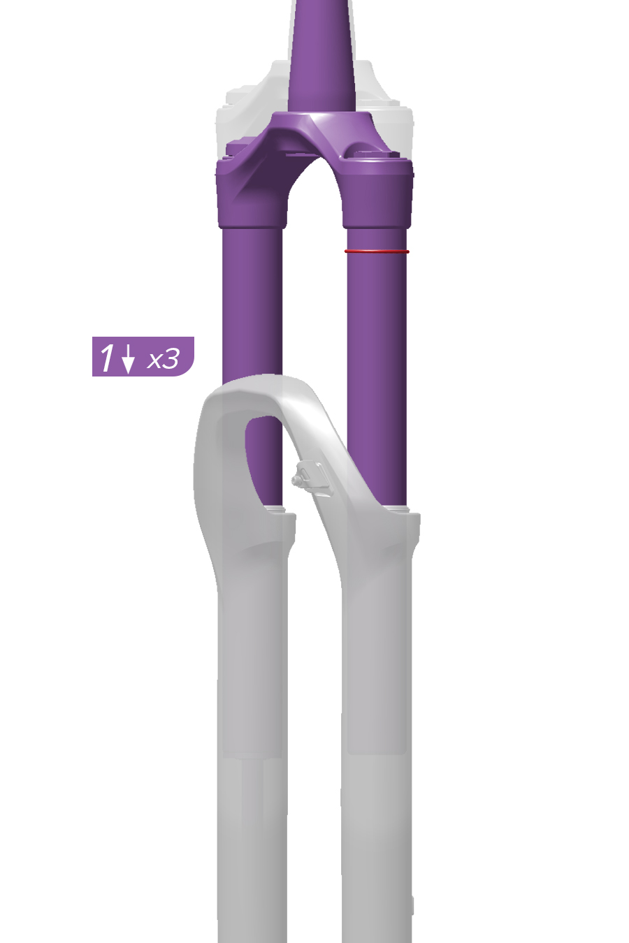
1. With riding gear on, and an assistant holding the bike, stand on the pedals, and compress the fork three times. Then sit or stand in your normal riding position.
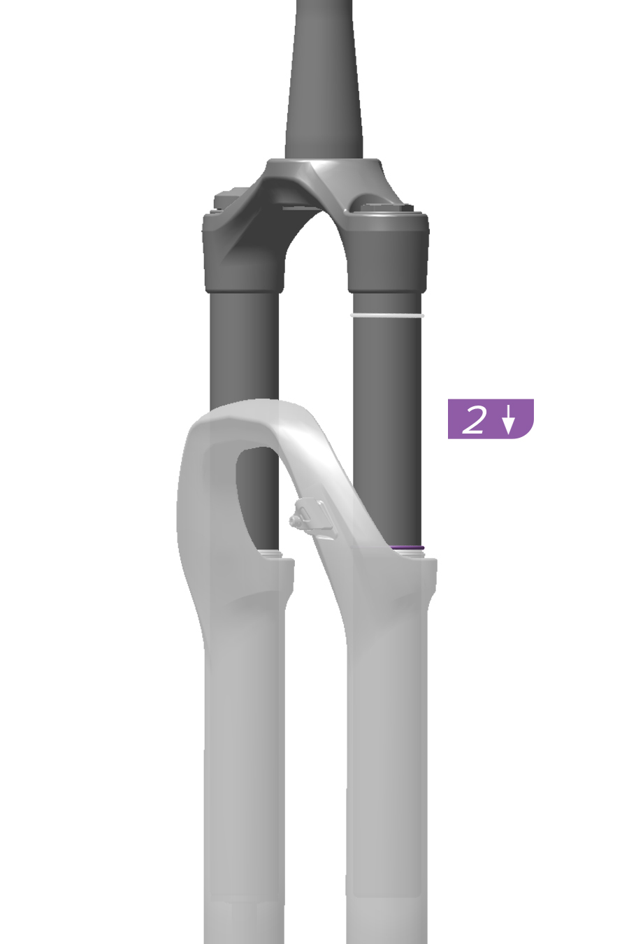
2. Have your assistant slide the sag o-ring down to the top of the dust seal.
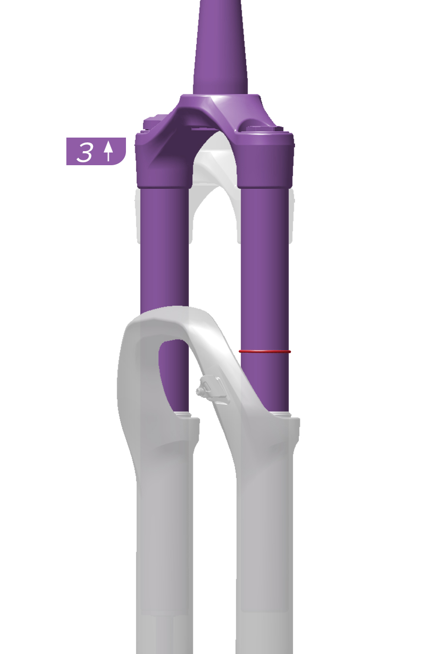
3. Gently step off the bicycle without compressing the fork any further.
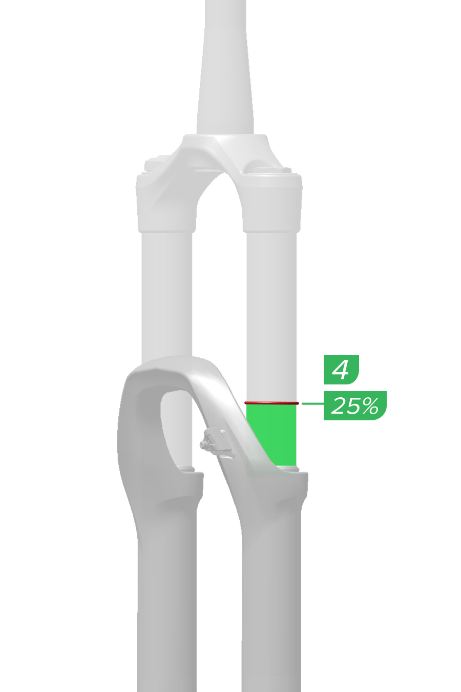
4. Note the sag percentage where the o-ring stopped.
If your target sag percentage is not achieved, spring preload adjustment and/or coil spring replacement must be performed.
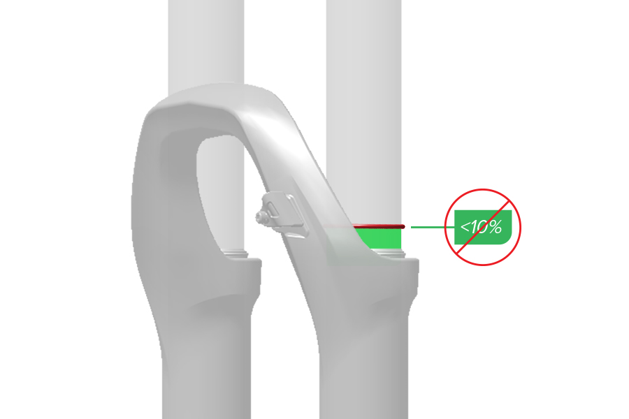
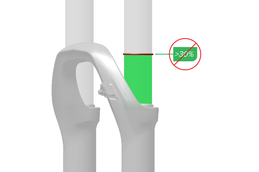
Preload spacers compress or decompress the spring without initiating travel.
The coil spring can be preloaded with the maximum number of preload spacers specified for the fork model. Refer to the Service Manual for your fork for more information.
Remove preload spacers to decrease preload and increase sag.
Install preload spacers to increase preload and decrease sag.
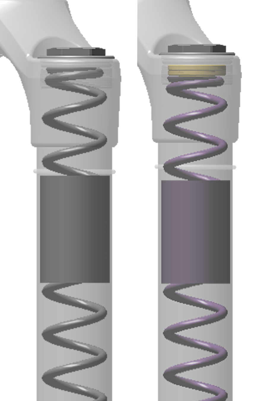
Spring preload can be used to fine tune sag, but preload does not change coil spring rate and is not a substitute for the proper coil spring.
If your target sag cannot be achieved with the maximum number of preload spacers, replace the coil spring with a firmer spring.
If your target sag cannot be achieved with zero preload spacers, replace the coil spring with a softer spring.
Repeat the sag process until your target sag percentage is achieved.
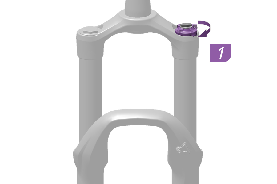
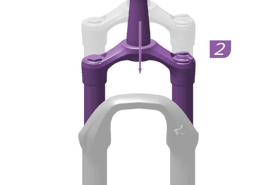
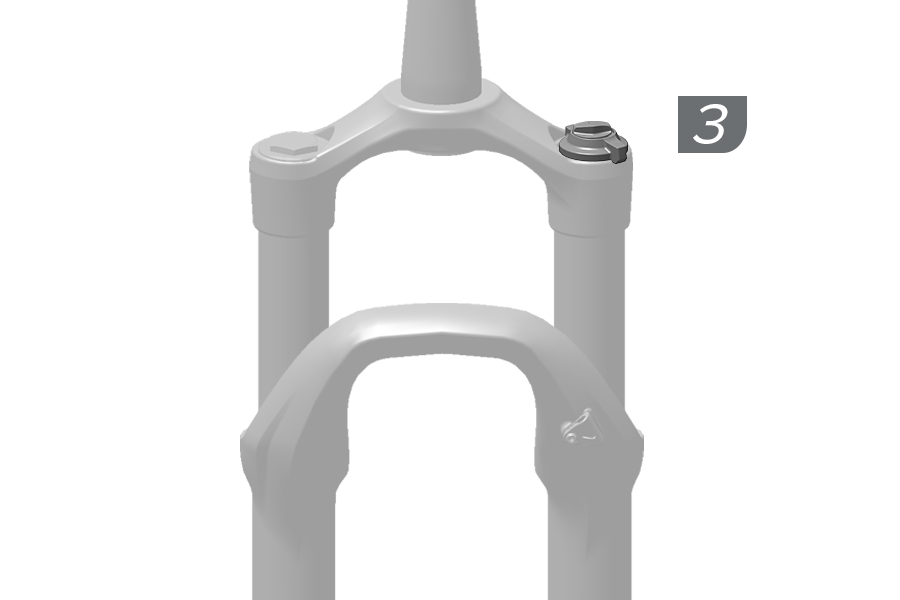
REDUCE TRAVEL
1. To reduce travel, rotate the adjuster knob to the minimum travel position.
2. Compress the fork until spring travel change engagement is felt. Continue to compress then release and allow the fork to extend and lock into the minimum travel position.
3. The fork is now set to the minimum travel position.
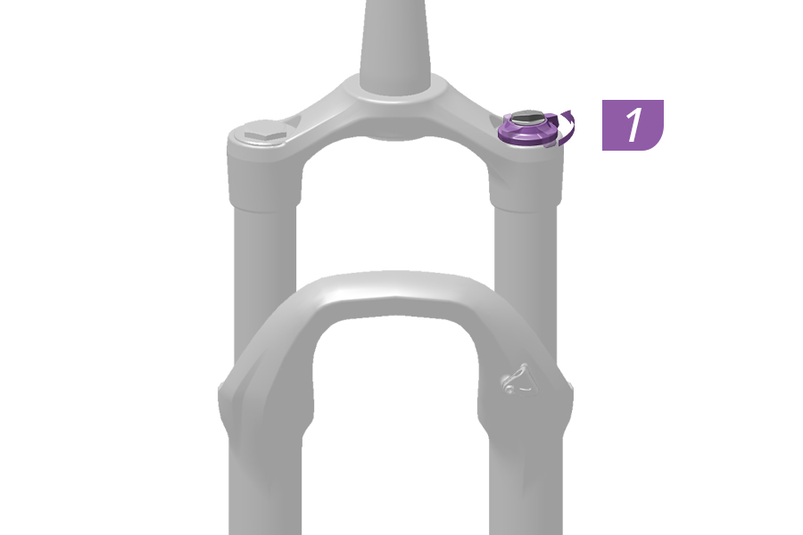
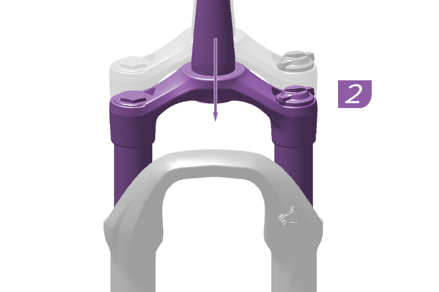
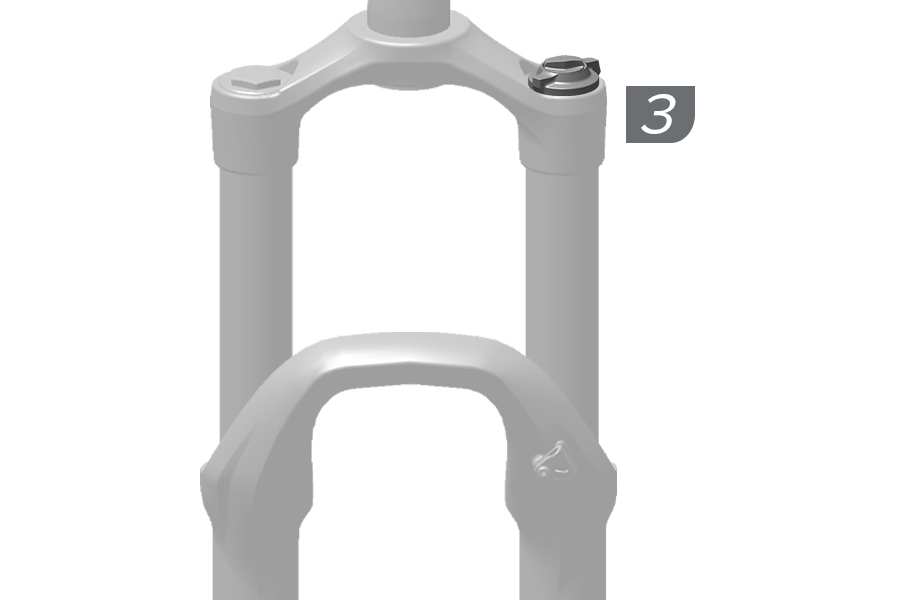
INCREASE TRAVEL
1. To increase travel, rotate the adjuster knob to the maximum travel position.
2. Compress the fork until spring travel change engagement is felt. Continue to compress, then release and unweight the fork slightly to allow the fork to extend and lock into the maximum travel position.
3. The fork is now set to the maximum travel position.
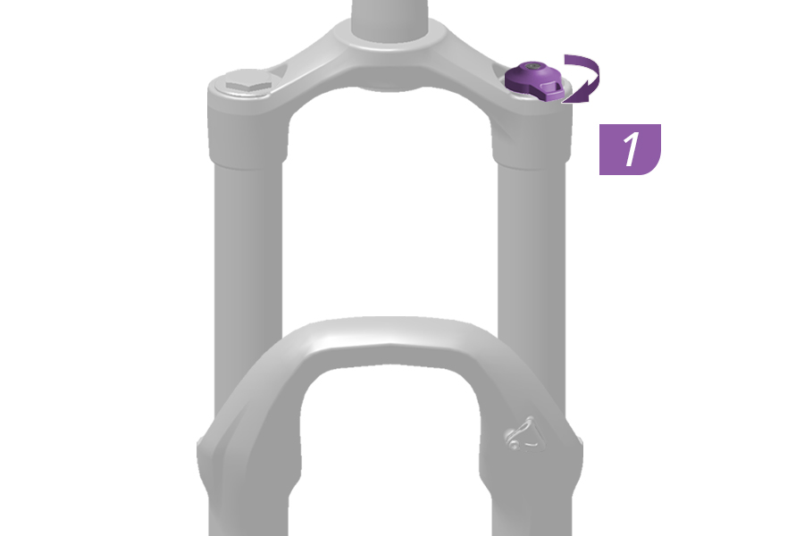
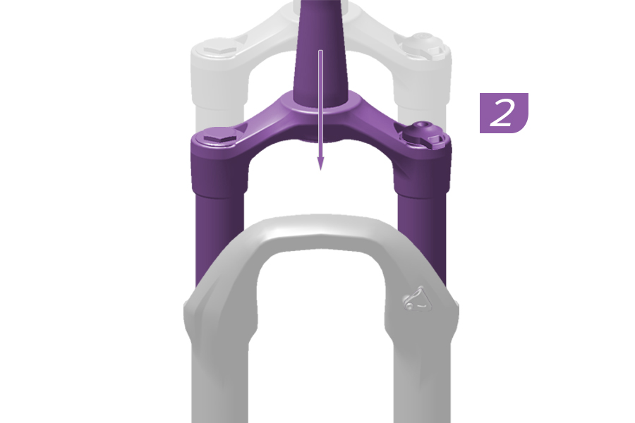
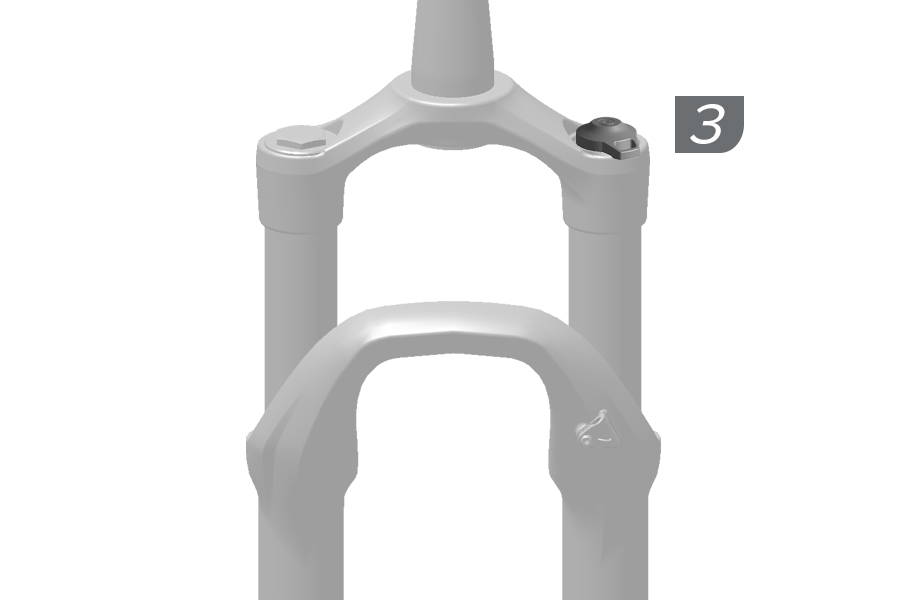
REDUCE TRAVEL
1. To reduce travel, rotate the adjuster knob to the minimum travel position.
2. Compress the fork until spring travel change engagement is felt. Continue to compress then release and allow the fork to extend and lock into the minimum travel position.
3. The fork is now set to the minimum travel position.
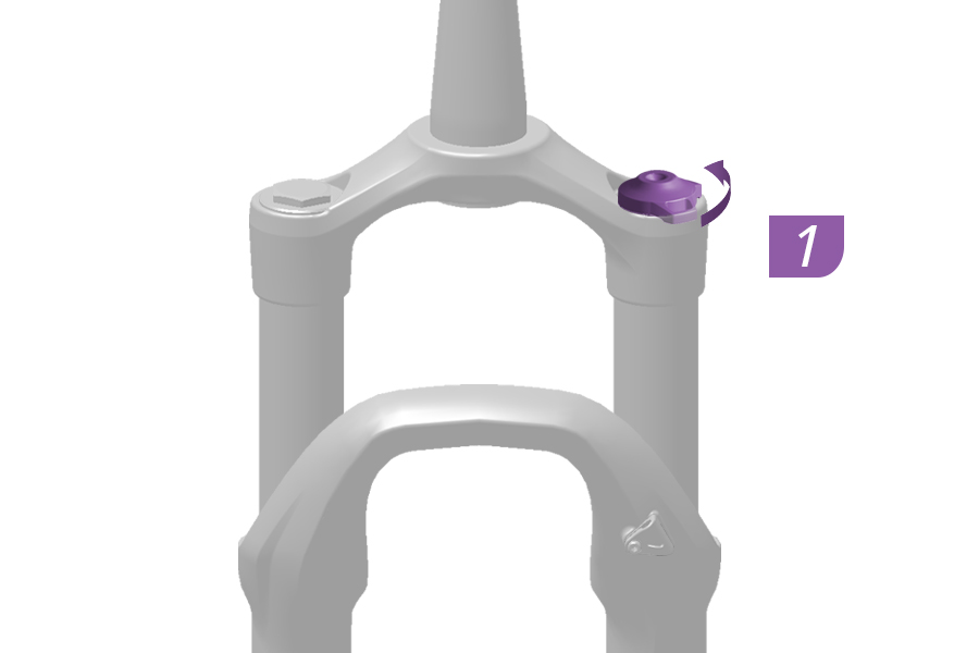
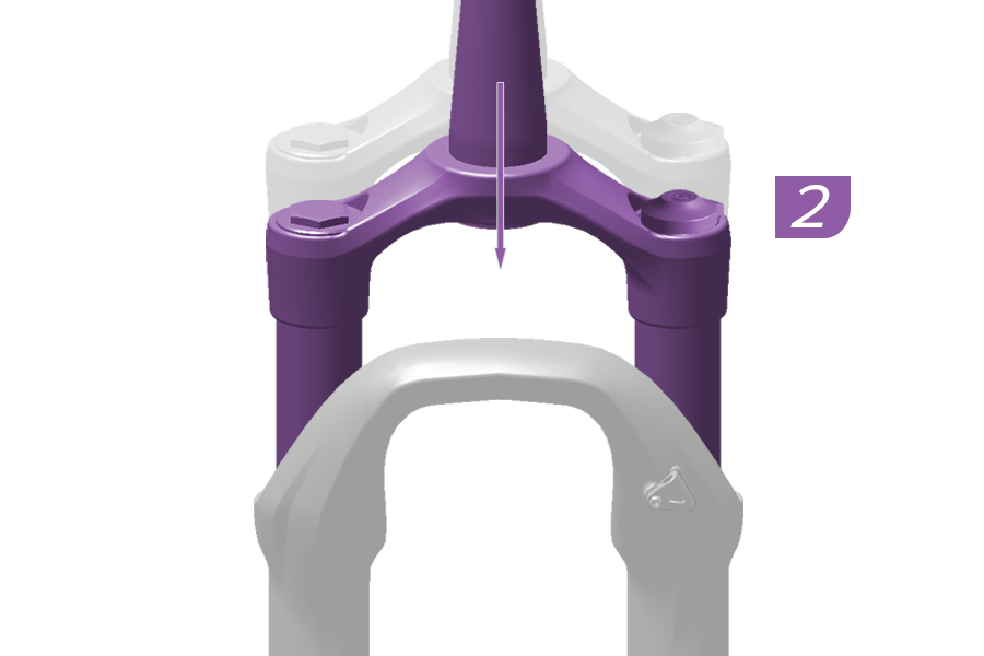
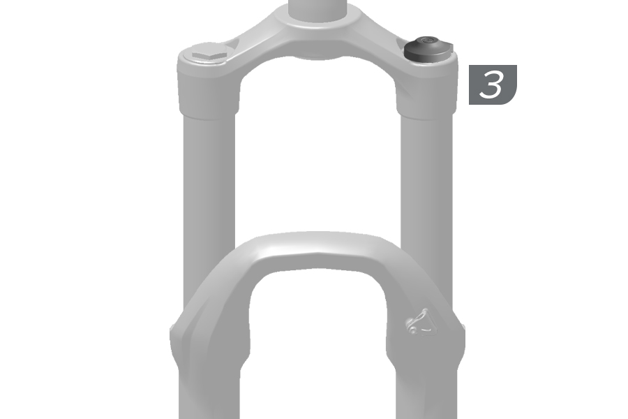
INCREASE TRAVEL
1. To increase travel, rotate the adjuster knob to the maximum travel position.
2. Compress the fork until spring travel change engagement is felt. Continue to compress, then release and unweight the fork slightly to allow the fork to extend and lock into the maximum travel position.
3. The fork is now set to the maximum travel position.
To adjust air spring pressure:
1. Adjust all damper adjusters to the open position.
2. Remove the air cap.
3. Attach a high-pressure shock pump to the air inflation valve and inflate to the desired pressure.
4. Remove the shock pump from the shock.
5. Install the air cap.
See the Set Sag - Air Rear Suspension section for more details.
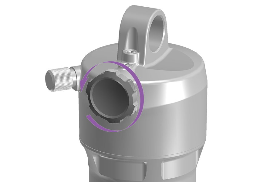

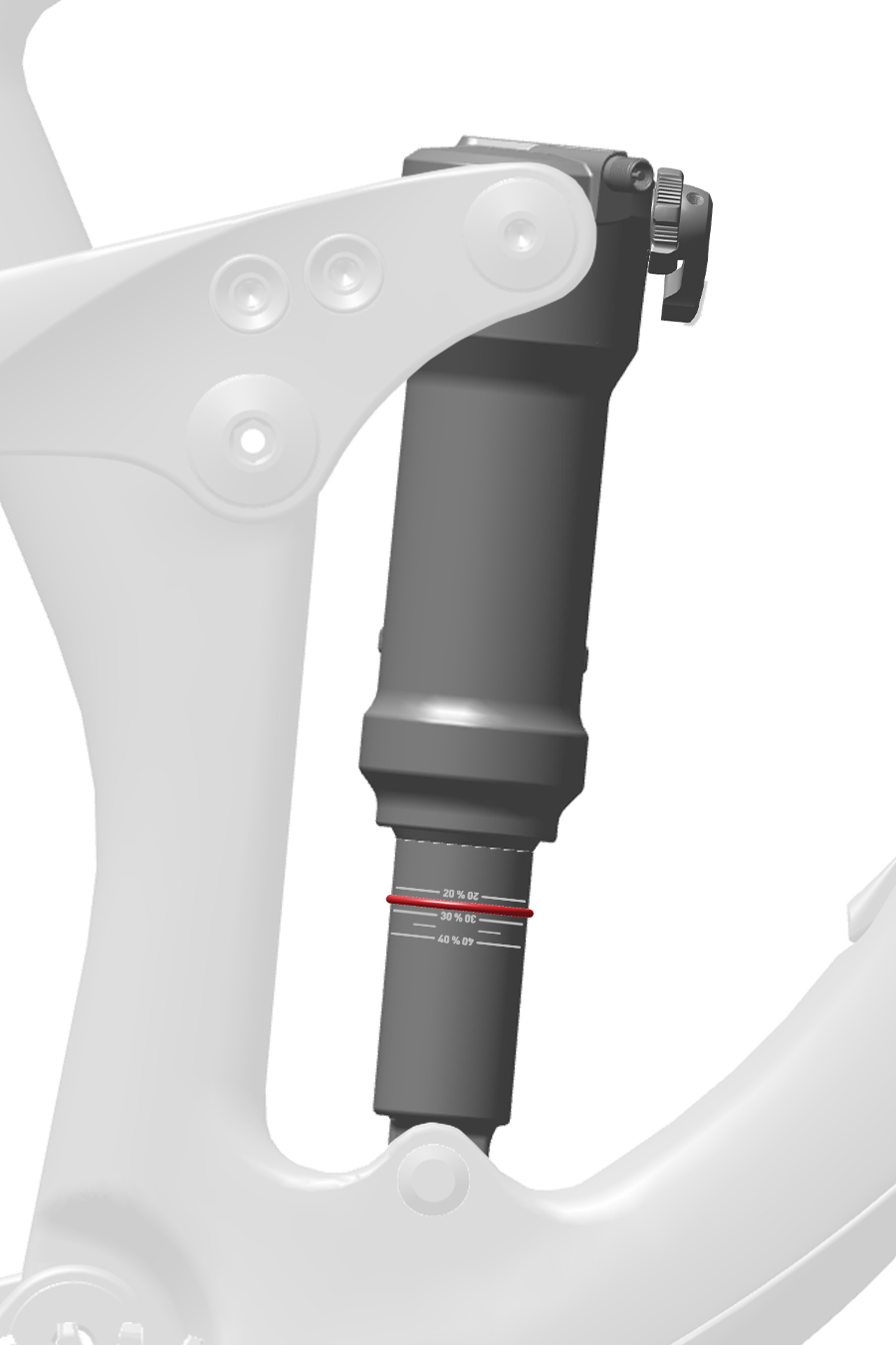
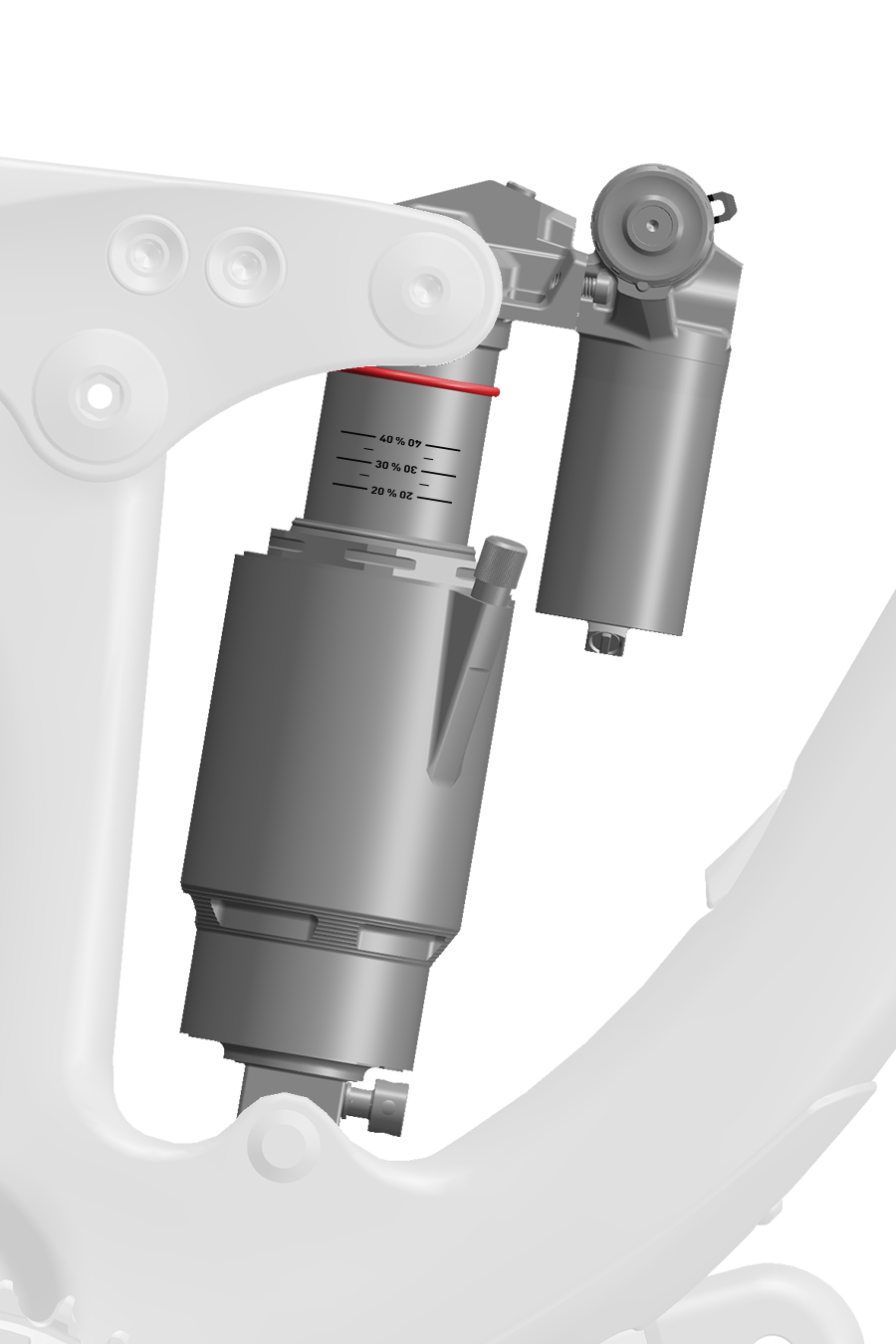
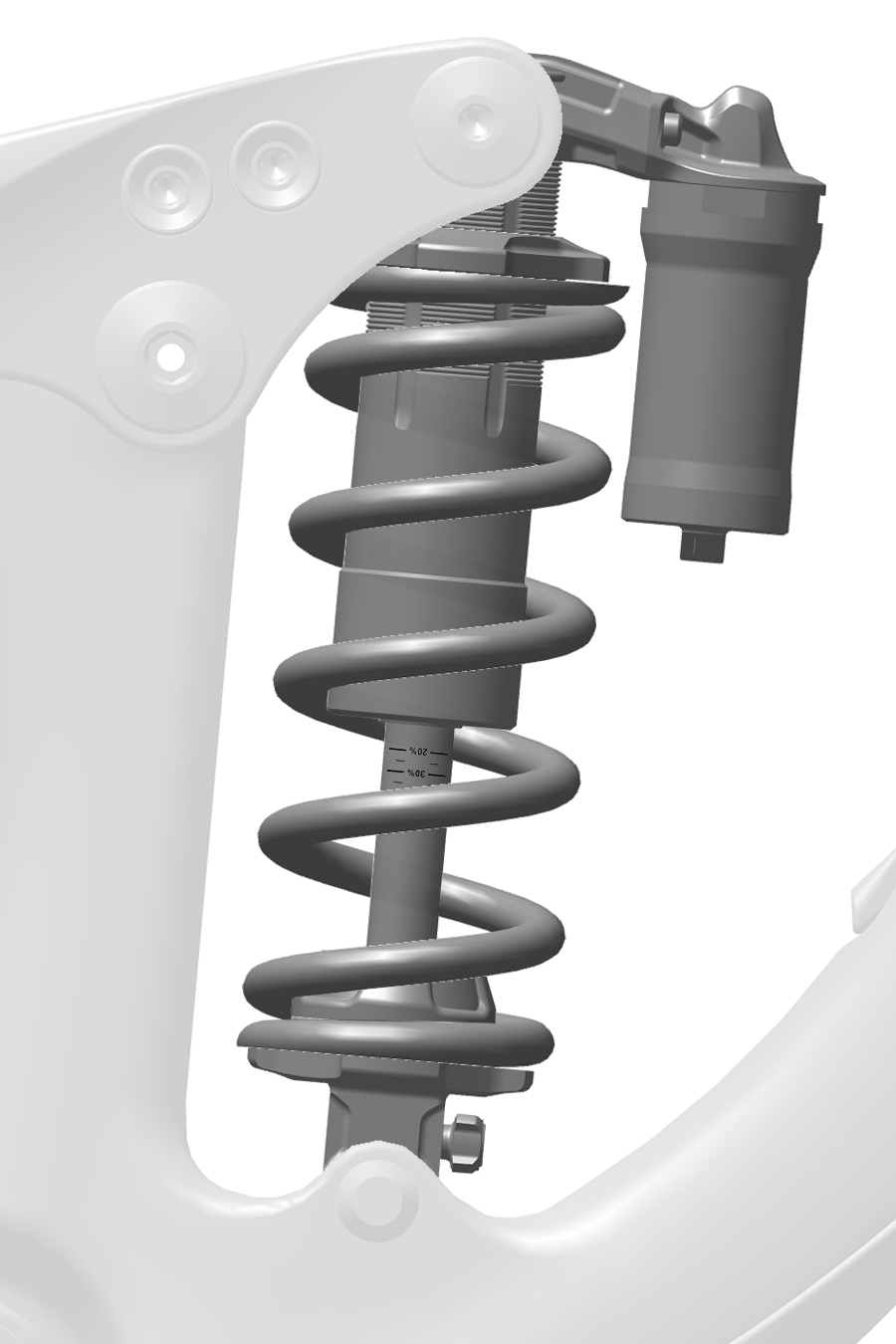
Suspension sag is the percentage of full travel that the suspension compresses when the rider, including gear, is on the bicycle in a normal riding position. Setting the correct sag allows the suspension to perform effectively. Optimal suspension sag is the result of setting the proper suspension spring rate.
More sag (20% - 30%) increases bump sensitivity and suspension movement. More bump sensivity results in a smoother ride and is typically preferred on longer travel bicycles.
Less sag (10% - 20%) decreases bump sensitivity and suspension movement. Less bump sensitivity results in a more firm, efficient ride and is typically preferred on shorter travel bicycles.
Too much sag is an indicator that the spring rate should be increased by either increasing air spring pressure or changing the coil spring to a stiffer spring.
Sag Gradients: Many RockShox forks and rear shocks include sag percentage gradients and a sag o-ring on one upper tube, or the rear shock body or shaft. If a sag o-ring is not on your suspension, install a plastic cable tie around the upper tube, shock body or shock shaft, just tight enough so it does not move. Remove the cable tie before riding.
If your fork or rear shock does not have sag percentage gradients, to calculate target sag, multiply the target sag percentage by the total amount of suspension travel. Use a ruler to measure the length of exposed upper tube, damper body or shock shaft above the wiper seal to the sag o-ring.
If your suspension's travel is unknown, before sag is measured, fully compress the suspension to bottom out. Release and use a ruler to measure the length of exposed upper tube, damper body, or shock shaft below the sag o-ring or stopping point of the wiper seal.
Getting Started:
Rear shocks are available with an air spring or coil spring. Due to the specificity of frame designs, it is best to follow the Set Sag - Rear Suspension (Air or Coil) procedure to determine the correct spring rate. Rear shock coil springs are available in a number of spring rates based on the eye-to-eye shock length and compression stroke dimensions of your shock. Refer to the (RockShox) Spare Parts Catalog for available springs.
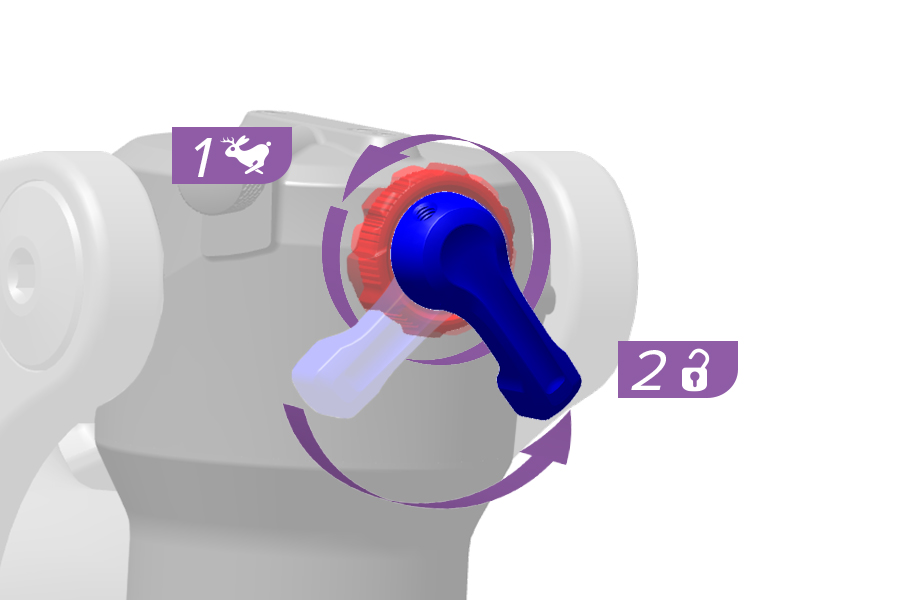
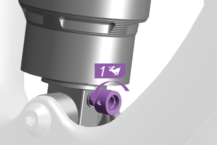
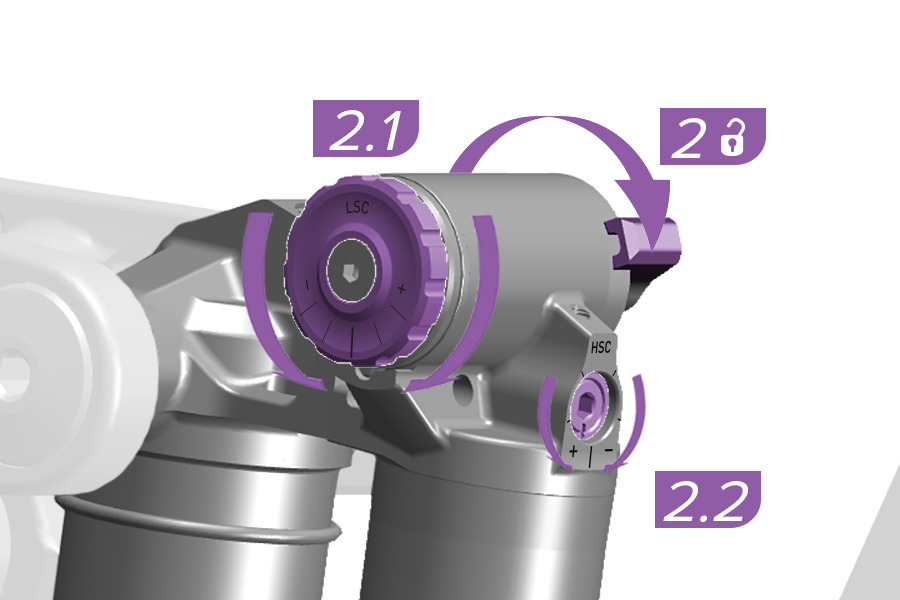
1-2. Before setting sag, set the adjusters to the unlocked or full open positions. Rotate the adjusters counterclockwise until they stop, to the unlocked or full open setting.
Vivid Air (Gen C): Before setting sag, rotate the Low Speed Compression (2.1) and High Speed Compression (2.2) adjusters to the middle setting.
Remote: Set the shock to the open position.
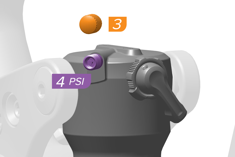
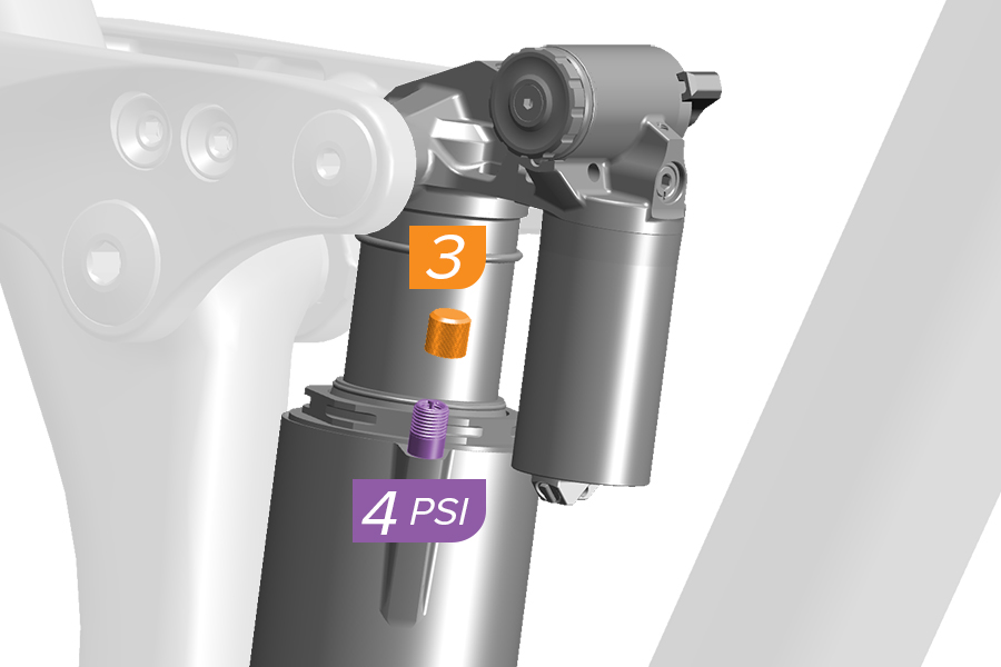
3. Remove the air cap.
4. Beginning with the shock fully deflated, pressurize the air spring chamber to 100 psi.
Vivid Air (Gen C): Beginning with the shock fully deflated, pressurize the air spring chamber to 50 psi.
Remove the pump. Do not compress the suspension with the pump attached.
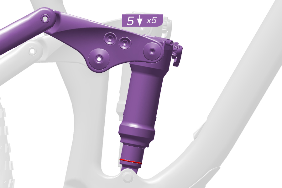
5. Fully compress the shock five times to equalize the positive and negative air springs. Air pressure equalization ensures the air spring is accurately pressurized.
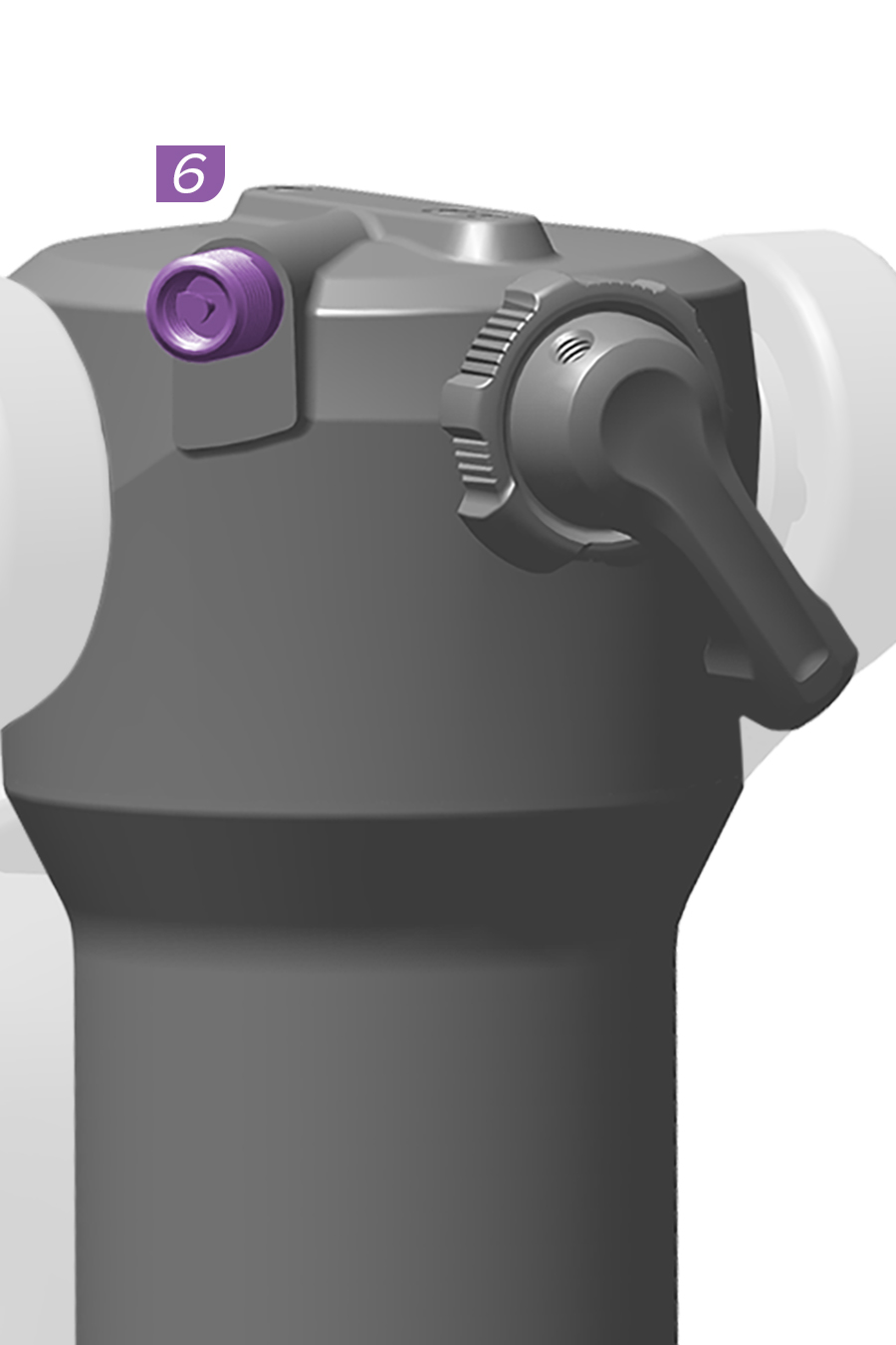
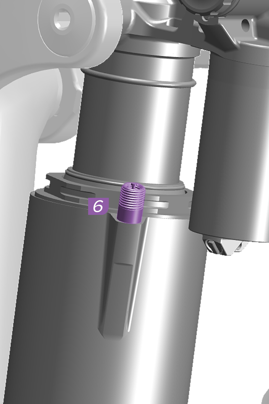
6. Pressurize the shock (PSI) to the equivalent of the rider's total weight (lbs), including gear. Example: 160 lbs = 160 PSI
Vivid Air (Gen C): Repeat steps 4 and 5 in 50 PSI increments up to the rider's total weight (lbs), including riding gear.
Remove the pump. Do not compress the suspension with the pump attached.
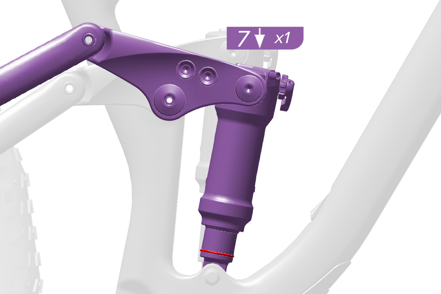
7. Compress the shock once more to equalize air pressure.
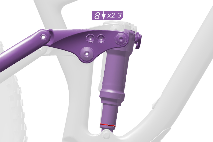
8. With riding gear on, and an assistant holding the bike, step onto the bicycle and lightly cycle the shock two to three times while in the standing position on the pedals.
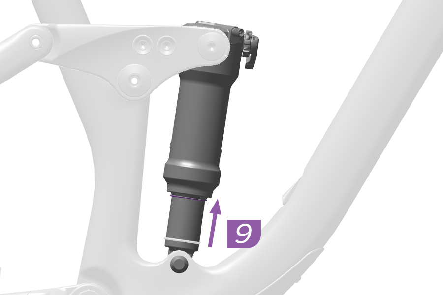
9. While seated on the bicycle, have an assistant slide the sag o-ring against the wiper seal.
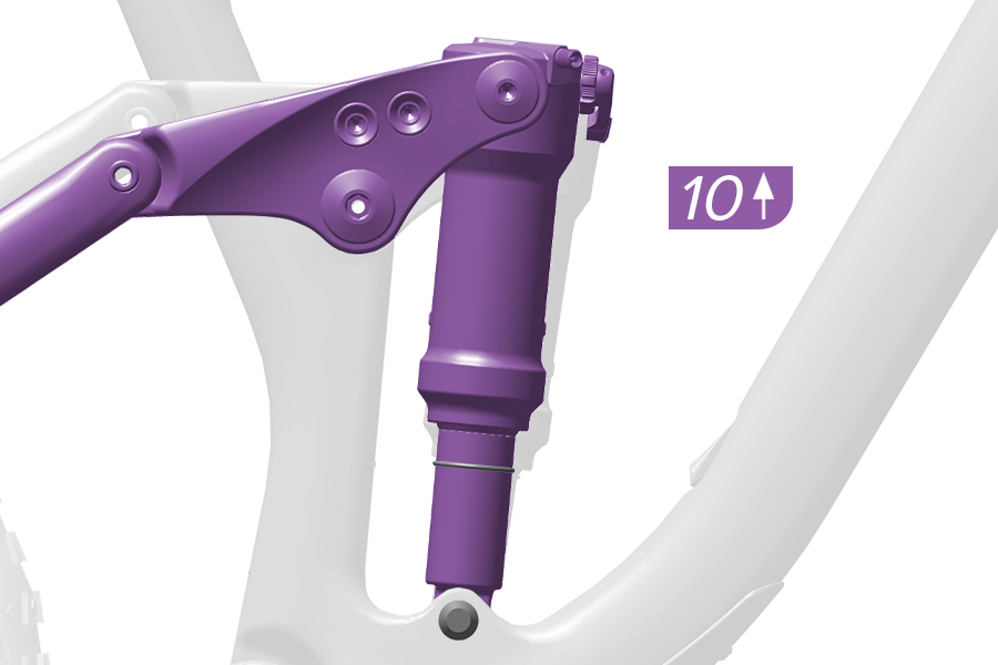
10. Gently step off the bicycle without compressing the shock.
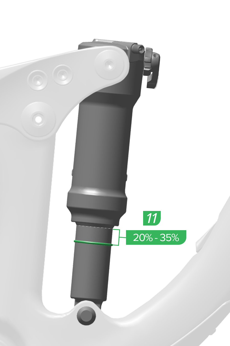
11. Note the sag percentage where the o-ring stopped.
Correct sag percentage for Solo Air shocks is ≈25%. Correct sag percentage for DebonAir shocks is ≈30%.
Sag can be set ±5% as preferred. Adjust pressure and retest sag as needed.
If your target sag percentage is not achieved, air pressure must be adjusted.
Increase air pressure to decrease sag.
Decrease air pressure to increase sag.
Refer to Coil Spring Installation for coil spring removal and installation procedures.
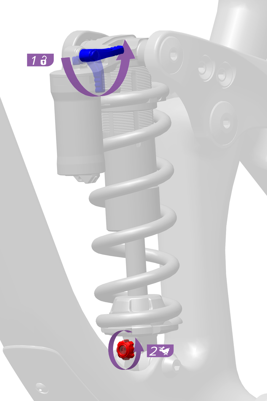
1-2. Set the rebound, compression, and threshold settings to the full open position.
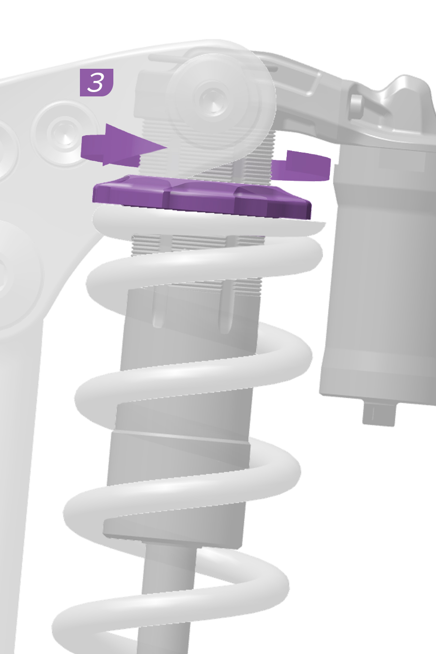
3. Turn the spring preload adjuster counterclockwise until there is no resistance.
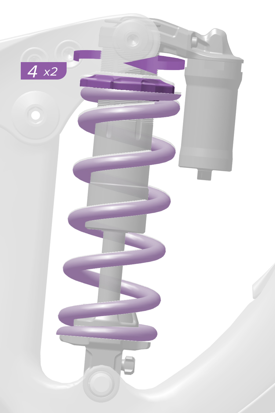
4. Turn the preload adjuster clockwise two full turns and stop.
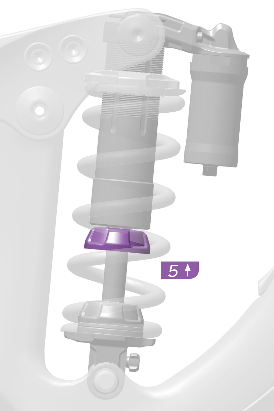
5. Slide the bottom out bumper to the shock body.
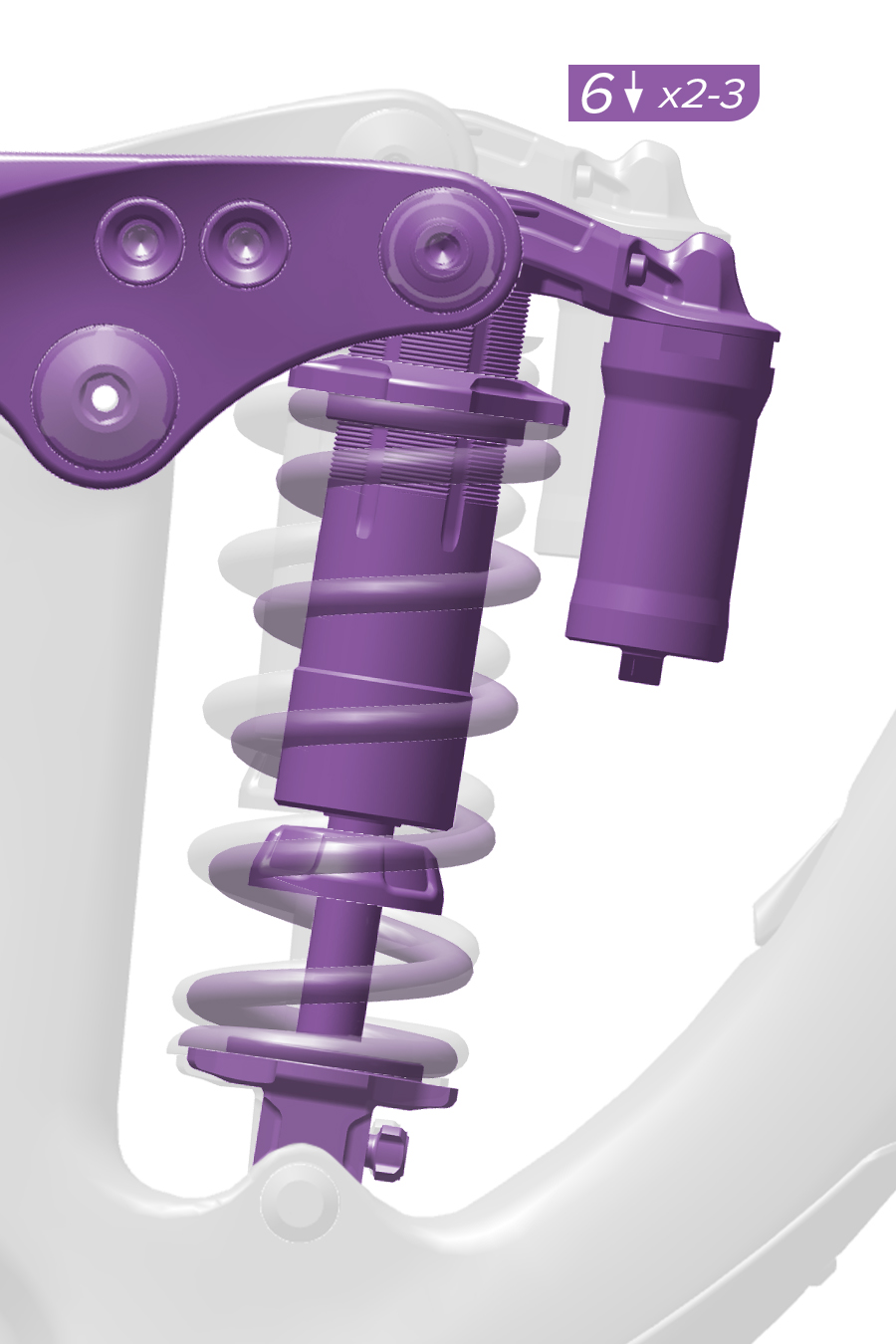
6. With riding gear on, and an assistant holding the bike, step onto the bicycle and lightly cycle the shock two to three times.
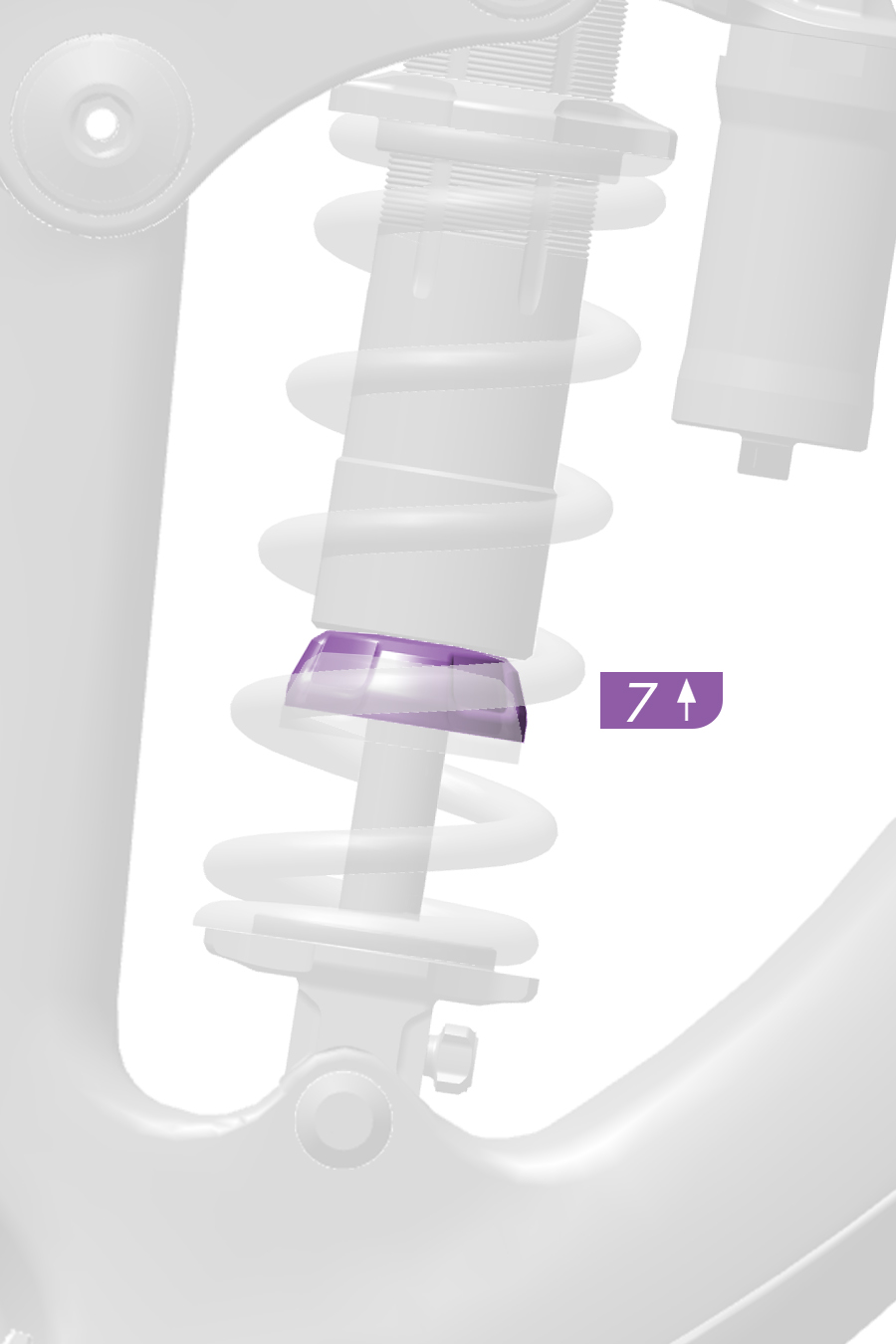
7. While seated on the bicycle, have an assistant slide the bottom out bumper against the wiper seal.
To avoid injury, use a non-metallic tool to slide the bumper. Do not use your finger.
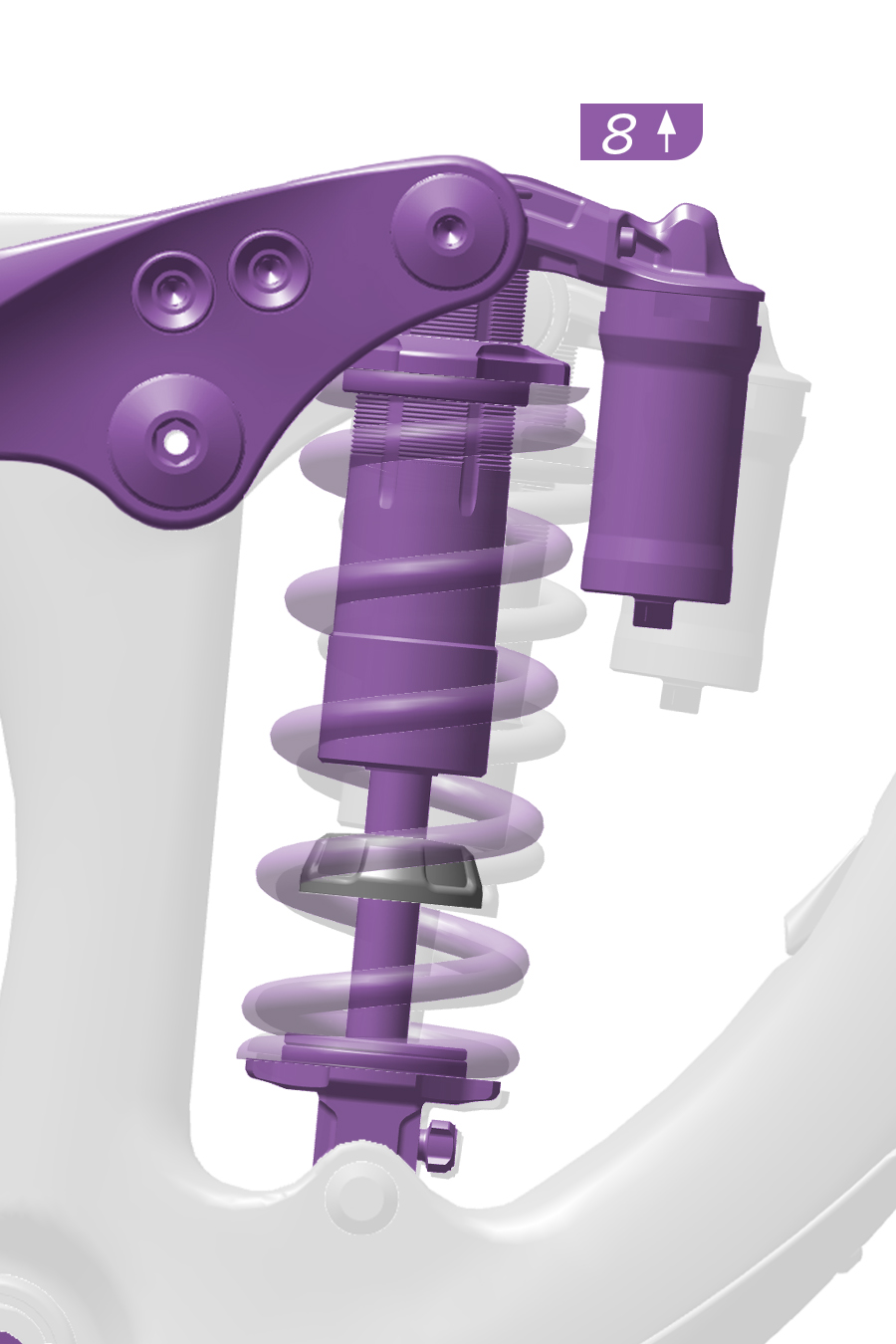
8. Gently step off of the bicycle without compressing the rear shock.
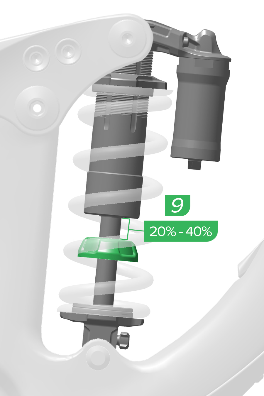
9. Check the top of the bottom out bumper position on the shock shaft and note the sag percentage marking.
If the shaft does not include markings measure the shaft length with a ruler.
Correct sag should be between 25% and 35%. Depending on your riding style and terrain, sag can be set 5% more or less than the recommended amount.
If the sag value is not at the desired level, turn the preload adjuster ring and repeat the measuring process until the desired sag value is achieved.
If the sag value is not at the desired level after five full clockwise turns, a heavier spring must be installed, and the sag setting procedure must be repeated.
Do not exceed five full turns of preload adjustment.
Ending stroke air spring ramp, or bottom out resistance, can be tuned on select RockShox air spring forks compatible with air spring volume reducing Bottomless Tokens, as well as select RockShox air spring rear shocks compatible with air spring volume reducer Bottomless Tokens and Rings.
Bottomless Tokens and Rings reduce air spring volume and increase bottom out resistance. Reduced volume, with the correct sag set, increases mid to ending stroke spring ramp without significantly affecting sag and small to medium bump sensitivity. Increased spring ramp at bottom out can be beneficial on larger drops or fast bumpy trails where the fork uses most of its travel.
If sag is set correctly and the suspension bottoms out quickly and often, try adding compatible Bottomless Tokens, or Rings, until you find the preferred bottom out feel.
It is recommended that you repeat the Sag process and make damping adjustments after volume reducers have been installed or removed. Adding volume reducers may cause the suspension to rebound quicker. Rebound damping may need to be increased to compensate.
To avoid damaging the fork or rear shock, the maximum number of Bottomless Tokens or Rings installed should not be exceeded. For suspension forks, refer to the appropriate model year RockShox Front Suspension Oil, Air, Coil, Token, and Specification document for the maximum number of Bottomless Tokens compatible with your fork. For rear shocks, refer to the Service Manual for your rear shock, for the maximum number of Bottomless Tokens and Rings.
For a complete list of available Bottomless Tokens and Rings consult the (RockShox) Spare Parts Catalog. For volume reducer installation and removal procedures, consult the service manual for your fork or rear shock. All related technical documents can be found at sram.com/service.
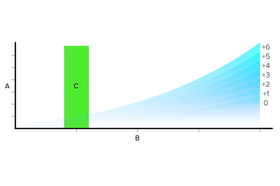
A | Compression Force |
B | Compression Stroke-Travel |
C | Sag 20%-30% |
0 through +6 | Token Count |
Additional rings or tokens increase bottom out resistance. Removing rings or tokens decrease bottom out resistance.
Front Suspension: Refer to the product Service Manual or the RockShox Front Suspension Oil, Air, Coil, Token, and Specification document for the maximum number of Bottomless Tokens.
Rear Suspension: Refer to the product Service Manual for the maximum number of Bottomless Tokens and Rings.
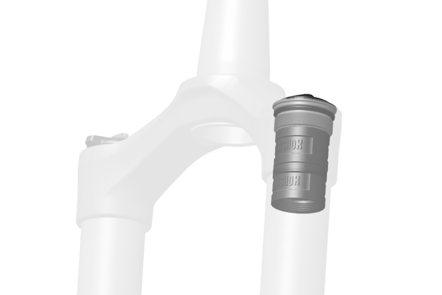
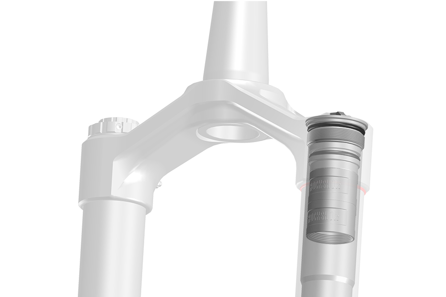
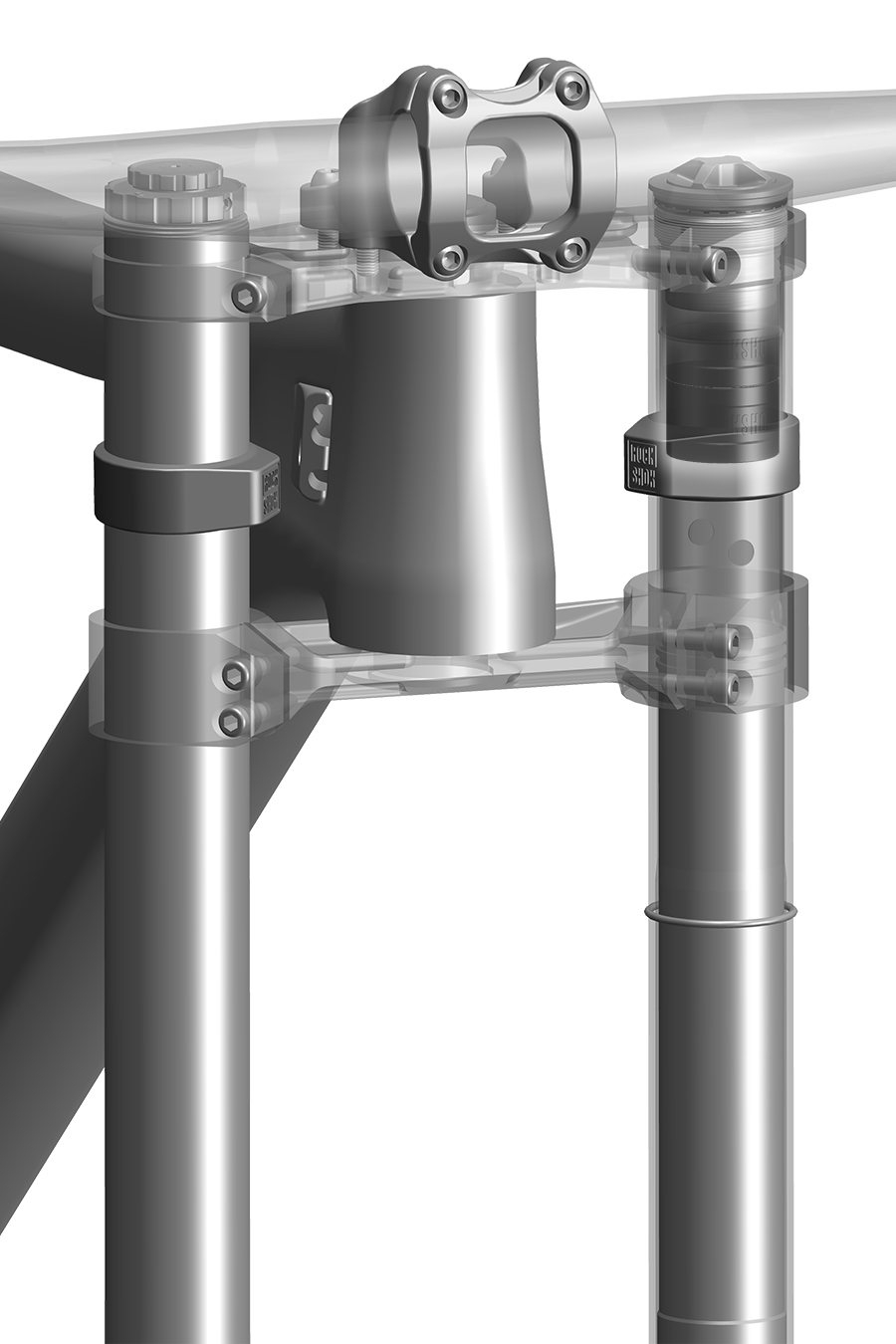
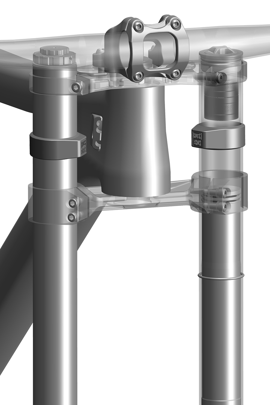
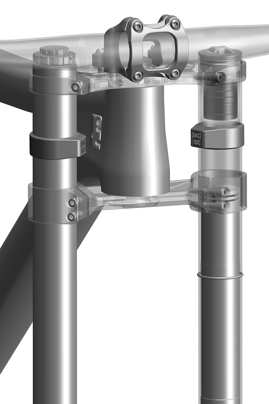
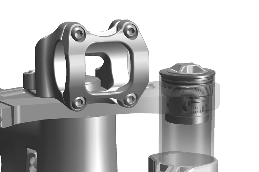
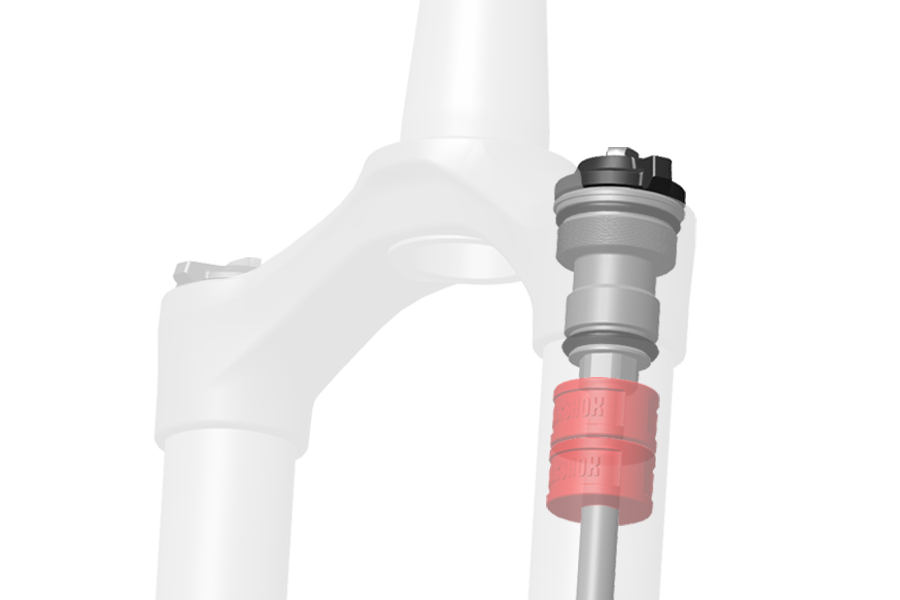
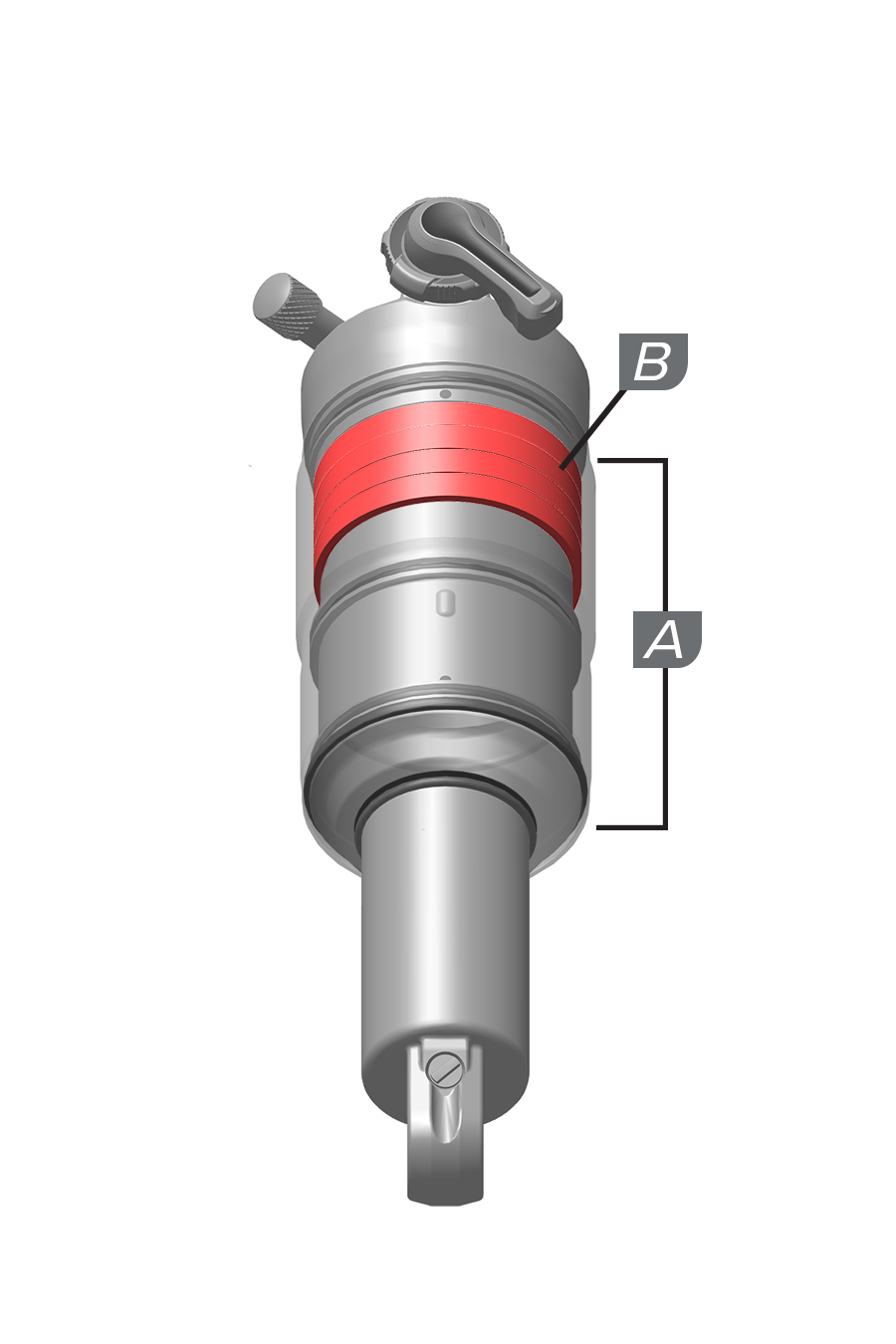
Shock Stroke | Volume Reducer | Quantity (Minimum-Maximum) |
|---|---|---|
38.1 mm (A) | Bottomless Ring | 0-4 (B) |
44.5 mm (A) | Bottomless Ring | 0-5 (B) |
50.8 mm (A) | Bottomless Ring | 0-8 (B) |
57.1 mm (A) | Bottomless Ring | 0-8 (B) |
63.5 mm (A) | Bottomless Ring | 0-8 (B) |
66.0 mm (A) | Bottomless Ring | 0-9 (B) |
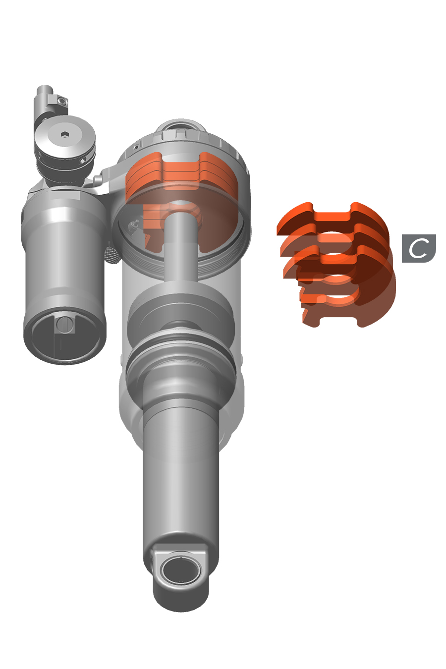
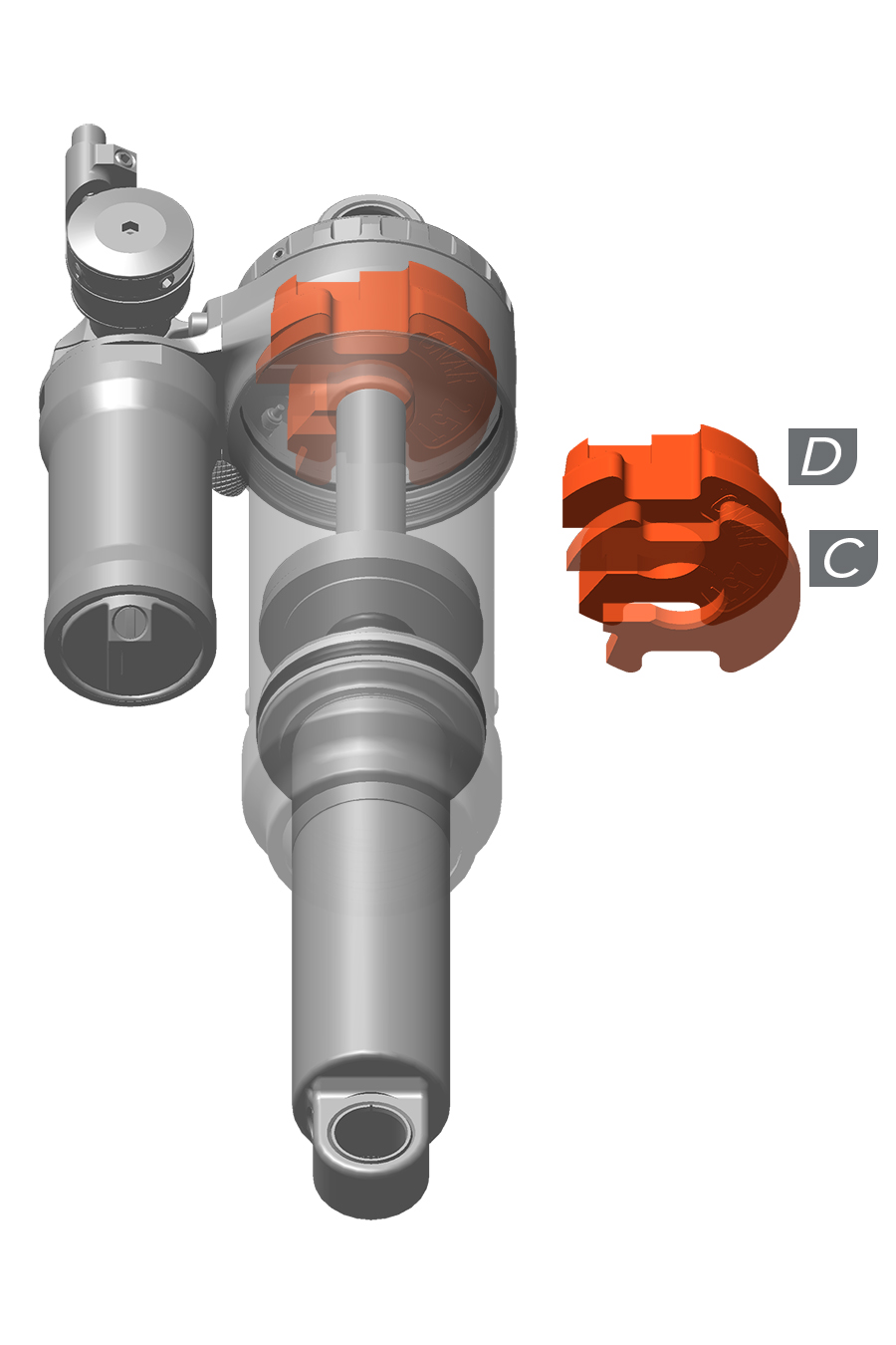
Volume Reducer | Quantity Option 1 (Minimum-Maximum) | Quantity Option 2 (Minimum-Maximum) |
|---|---|---|
Bottomless Token (C) & (D) | 0-3 (C) | 1 or 2 (C) + 1 (D) |
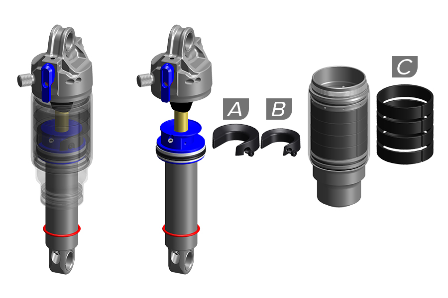
SEALHEAD / FIXED PISTON VOLUME REDUCER (1 Large = 2 Small) | QUANTITY INSTALLED (MINIMUM - MAXIMUM) | LINEAR XL AIR CAN VOLUME REDUCER | QUANTITY INSTALLED (MINIMUM - MAXIMUM) | NET TOTAL MAXIMUM QUANTITY INSTALLED |
|---|---|---|---|---|
Bottomless Token Large (A) | 0-1 | Air Sleeve Bottomless Token (C) | 0-4 | 6 |
Bottomless Token Small (B) | 0-1 | Air Sleeve Bottomless Token (C) | 0-4 | 5 |
Volume reducers can be installed onto the sealhead/ fixed piston and/or on the Linear XL air can to achieve the same effect.
1 Bottomless Token Large (A) equals 2 Linear XL air can Sleeve Tokens (C).
1 Bottomless Token Small (B) equals 1 Linear XL air can Sleeve Token (C).
SEALHEAD / FIXED PISTON VOLUME REDUCER (1 Large = 2 Small) | QUANTITY INSTALLED | LINEAR XL AIR CAN VOLUME REDUCER | QUANTITY INSTALLED | NET TOTAL QUANTITY INSTALLED |
|---|---|---|---|---|
Bottomless Token Large (A) | 0 | Air Sleeve Bottomless Token (C) | 0 | 0 |
Bottomless Token Large (A) | 0 | Air Sleeve Bottomless Token (C) | 1 | 1 |
Bottomless Token Large (A) | 0 | Air Sleeve Bottomless Token (C) | 2 | 2 |
Bottomless Token Large (A) | 0 | Air Sleeve Bottomless Token (C) | 3 | 3 |
Bottomless Token Large (A) | 0 | Air Sleeve Bottomless Token (C) | 4 | 4 |
Bottomless Token Large (A) | 1 | Air Sleeve Bottomless Token (C) | 0 | 2 |
Bottomless Token Large (A) | 1 | Air Sleeve Bottomless Token (C) | 1 | 3 |
Bottomless Token Large (A) | 1 | Air Sleeve Bottomless Token (C) | 2 | 4 |
Bottomless Token Large (A) | 1 | Air Sleeve Bottomless Token (C) | 3 | 5 |
Bottomless Token Large (A) | 1 | Air Sleeve Bottomless Token (C) | 4 | 6 |
Bottomless Token Small (B) | 0 | Air Sleeve Bottomless Token (C) | 0 | 0 |
Bottomless Token Small (B) | 0 | Air Sleeve Bottomless Token (C) | 1 | 1 |
Bottomless Token Small (B) | 0 | Air Sleeve Bottomless Token (C) | 2 | 2 |
Bottomless Token Small (B) | 0 | Air Sleeve Bottomless Token (C) | 3 | 3 |
Bottomless Token Small (B) | 0 | Air Sleeve Bottomless Token (C) | 4 | 4 |
Bottomless Token Small (B) | 1 | Air Sleeve Bottomless Token (C) | 0 | 1 |
Bottomless Token Small (B) | 1 | Air Sleeve Bottomless Token (C) | 1 | 2 |
Bottomless Token Small (B) | 1 | Air Sleeve Bottomless Token (C) | 2 | 3 |
Bottomless Token Small (B) | 1 | Air Sleeve Bottomless Token (C) | 3 | 4 |
Bottomless Token Small (B) | 1 | Air Sleeve Bottomless Token (C) | 4 | 5 |
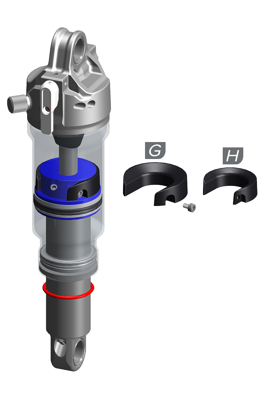
Volume Reducer | Quantity (Minimum-Maximum) |
|---|---|
Bottomless Token Large (G) | 1 Max (G) |
Bottomless Token Small (H) | 1 Max (H) |
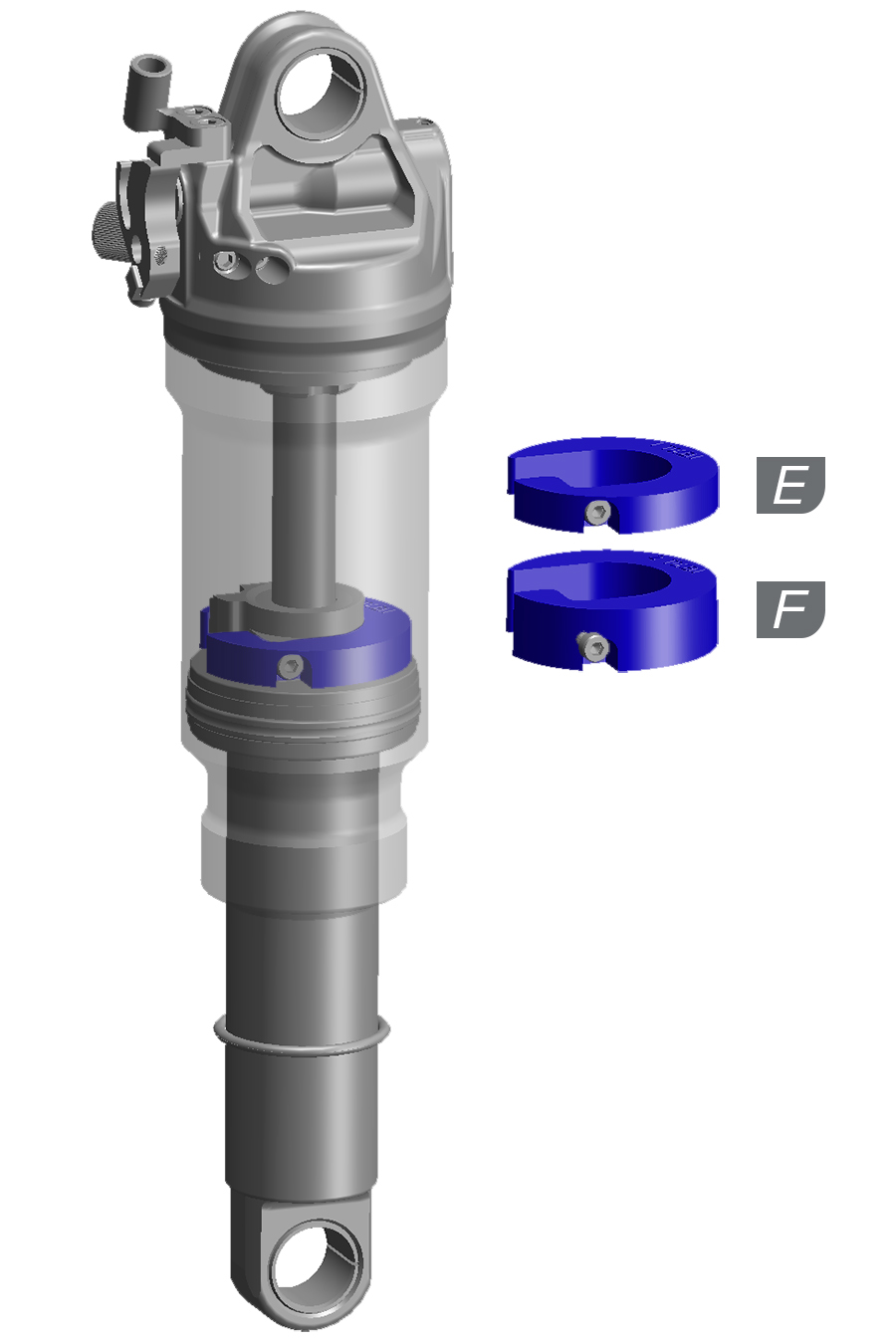
Volume Reducer | Quantity (Minimum-Maximum) |
|---|---|
Bottomless Token (E) | 1 Max (E) |
Bottomless Token (F) | 1 Max (F) |
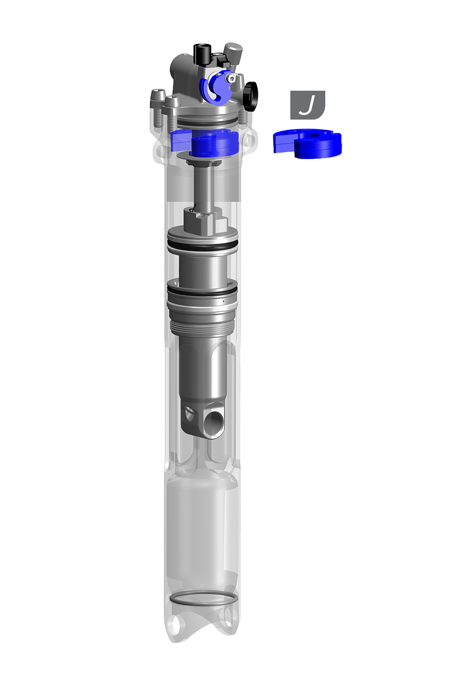
Volume Reducer | Quantity (Minimum-Maximum) |
|---|---|
Bottomless Token (J) | 2 Max (J) |
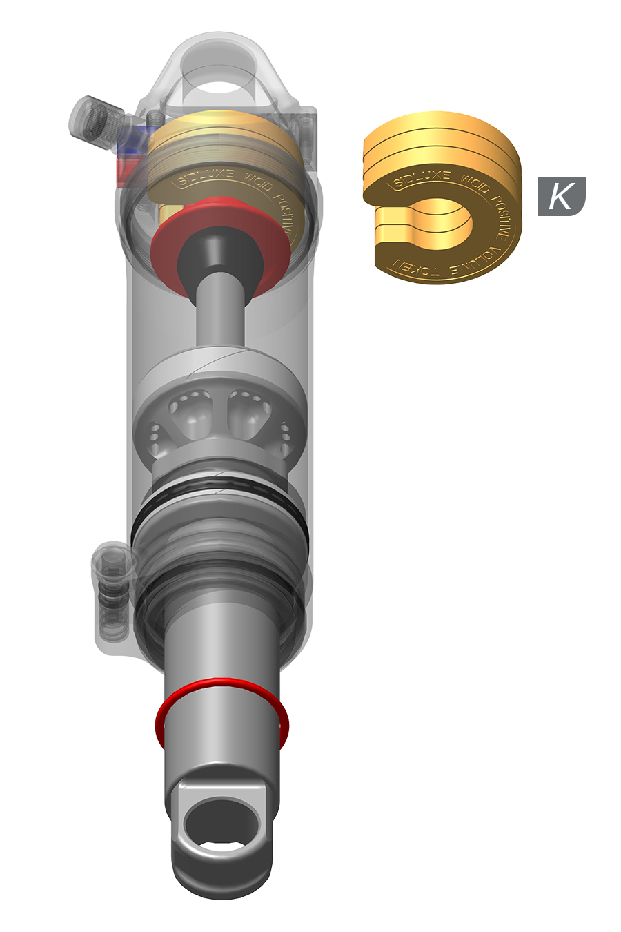
Volume Reducer | Quantity (Minimum-Maximum) |
|---|---|
Bottomless Token (K) | 3 Max (K) |
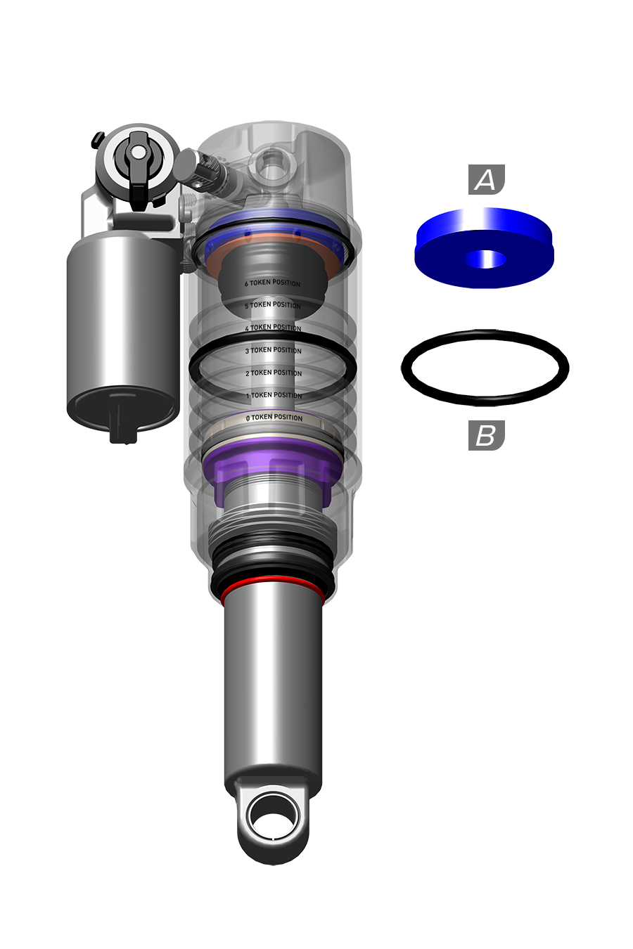
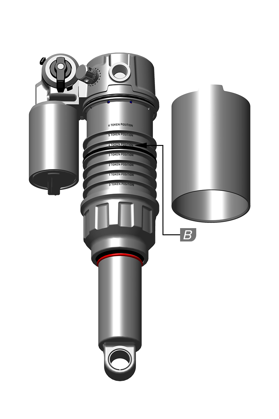
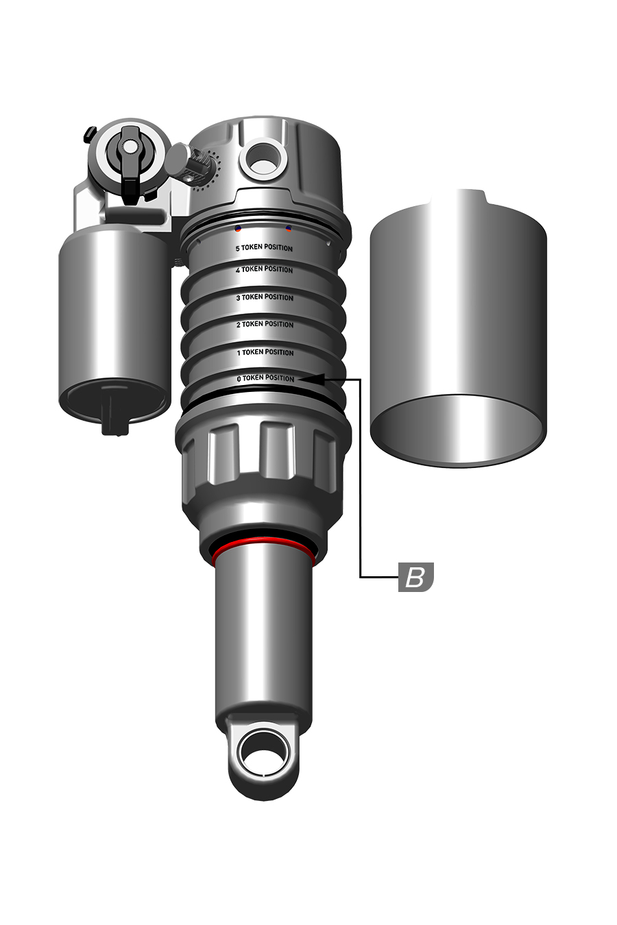
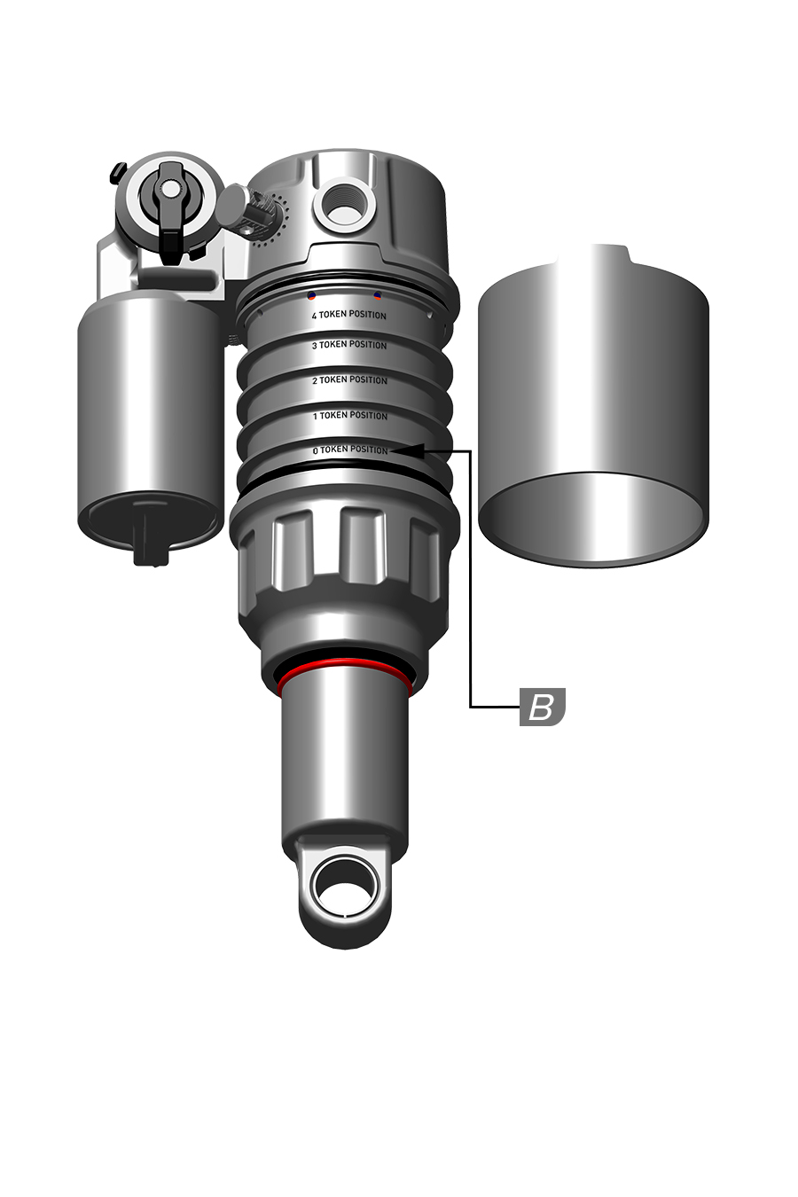
Shock Length (mm) | Shock Stroke (mm) | A. Travel Limiter x1 (mm) | B. Linear XL Air Can - O-Ring Token Position (minimum - maximum position) |
|---|---|---|---|
165, 190 | 37.5 | 7.5 | 0 - 4 |
165, 190 | 40 | 5 | 0 - 4 |
165, 190 | 42.5 | 2.5 | 0 - 4 |
165, 190 | 45 | 0 | 0 - 4 |
185, 210 | 47.5 | 7.5 | 0 - 5 |
185, 210 | 50 | 5 | 0 - 5 |
185, 210 | 52.5 | 2.5 | 0 - 5 |
185, 210 | 55 | 0 | 0 - 5 |
205, 230 | 57.5 | 7.5 | 0 - 6 |
205, 230 | 60 | 5 | 0 - 6 |
205, 230 | 62.5 | 2.5 | 0 - 6 |
205, 230 | 65 | 0 | 0 - 6 |
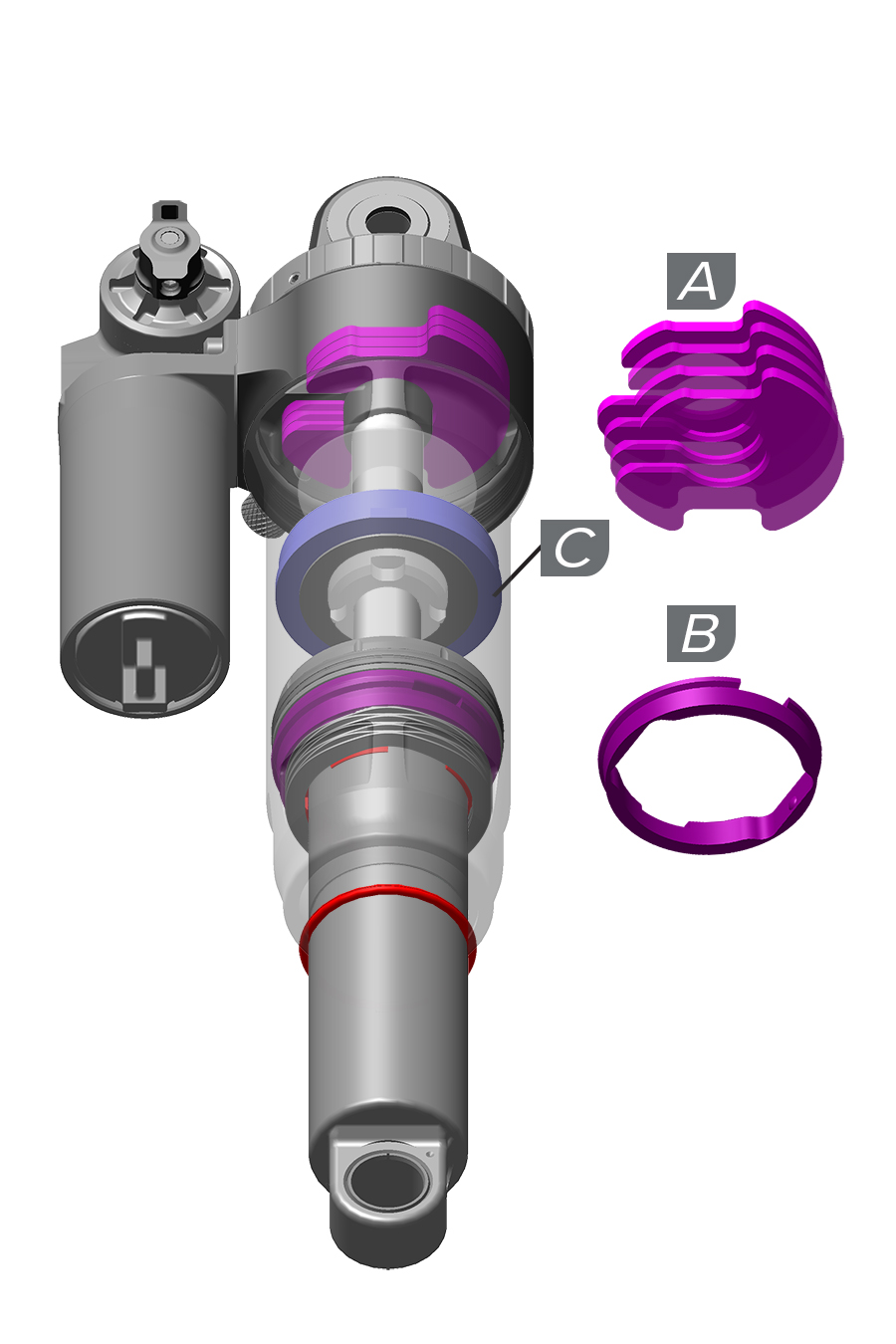
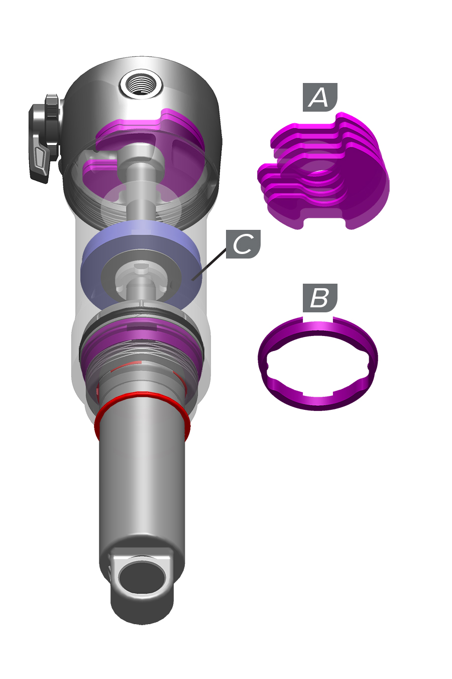
Volume Reducer | Quantity (Minimum-Maximum) |
|---|---|
Bottomless Token (A) | 0-4 |
Negative Volume Token (B) | 0-1 |
Travel Limiter (2.5 mm, 5 mm, 7.5 mm) (C) | 0-1 |
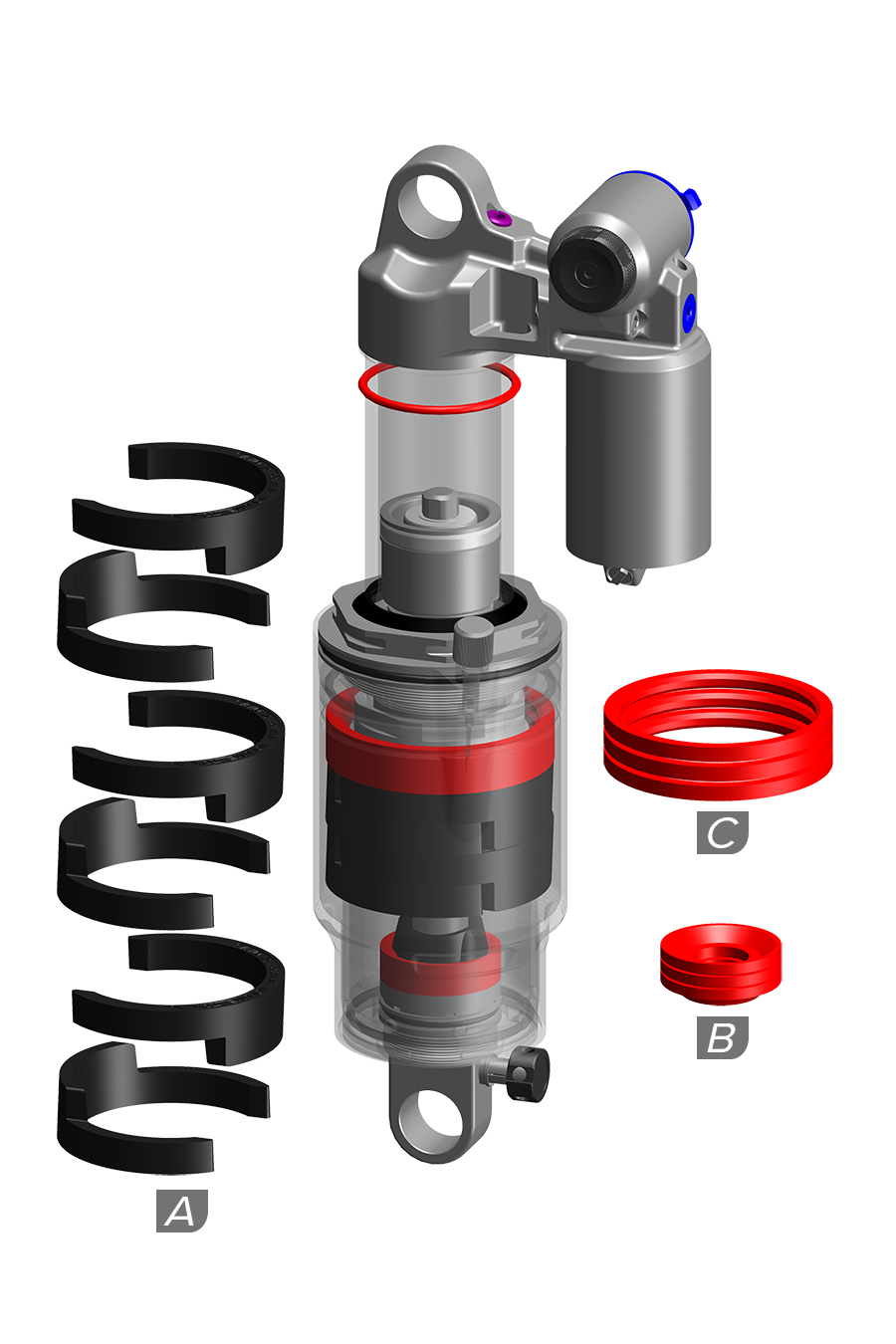
Shock Length (mm) (eye to eye) | Shock Stroke (mm) | Maximum PSI | Bottomless Token (A) |
|---|---|---|---|
185, 210 | 47.5-55 | 360 | 0-4 |
185, 210 | 47.5-55 | 300 | 5-6 |
205, 230 | 57.5-65 | 360 | 0-4 |
205, 230 | 57.5-65 | 300 | 5-6 |
225, 250 | 67.5-75 | 300 | 0-4 |
Shock Length (mm) (eye to eye) | Shock Stroke (mm) | Eyelet Travel Reducer (B) | Air Can Travel Volume Reducer (C) |
|---|---|---|---|
185, 210 | 47.5 | 3 | 3 |
185, 210 | 50 | 2 | 2 |
185, 210 | 52.5 | 1 | 1 |
185, 210 | 55 | 0 | 0 |
205, 230 | 57.5 | 3 | 3 |
205, 230 | 60 | 2 | 2 |
205, 230 | 62.5 | 1 | 1 |
205, 230 | 65 | 0 | 0 |
225, 250 | 67.5 | 3 | 3 |
225, 250 | 70 | 2 | 2 |
225, 250 | 72.5 | 1 | 1 |
225, 250 | 75 | 0 | 0 |
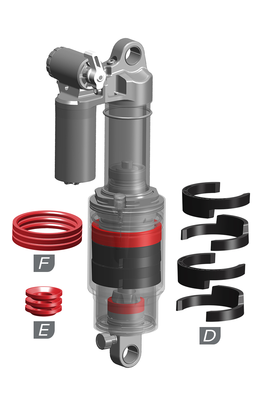
Shock Length (eye to eye) | Shock Stroke | Bottomless Token (D) - 360 MAX PSI |
|---|---|---|
165, 190 | 37.5-45 | 0-4 |
185, 210 | 47.5-55 | 0-4 |
185, 210 | 57.5-65 | 5-6 |
205, 230 | 57.5-65 | 0-4 |
205, 230 | 57.5-65 | 5-6 |
225, 250 | 67.5-75 | 0-4 |
Shock Length (eye to eye) | Shock Stroke | Eyelet Travel Reducer (E) | Air Can Travel Volume Reducer (F) |
|---|---|---|---|
165, 190 | 37.5 | 3 | 3 |
165, 190 | 40 | 2 | 2 |
165, 190 | 42.5 | 1 | 1 |
165, 190 | 45 | 0 | 0 |
185, 210 | 47.5 | 3 | 3 |
185, 210 | 50 | 2 | 2 |
185, 210 | 52.5 | 1 | 1 |
185, 210 | 55 | 0 | 0 |
205, 230 | 57.5 | 3 | 3 |
205, 230 | 60 | 2 | 2 |
205, 230 | 62.5 | 1 | 1 |
205, 230 | 65 | 0 | 0 |
225, 250 | 67.5 | 3 | 3 |
225, 250 | 70 | 2 | 2 |
225, 250 | 72.5 | 1 | 1 |
225, 250 | 75 | 0 | 0 |
To achieve maximum suspension performance, proper setup and tuning is essential.
Tuning sections in this manual will help to identify and understand the features and adjustments that may be included on your RockShox suspension, as well as guide you through spring setup, damper adjustments and tuning, and air spring bottom out tuning.
Tuning suggestions are starting points. It may take trying various adjustments to find the settings that work best for each individual rider, bicycle, and trail condition.
The Quarq ShockWiz suspension tuning device can be used for more detailed ride data analysis and setting suggestions. Go to sram.com/en/quarq for more information.
Go to RockShox Trailhead for suggested air spring pressure and rebound damper settings for your front suspension.
Go to sram.com/service for additional product and technical information.
Front suspension air spring pressure and coil spring tables are available in the RockShox Front Suspension Oil, Air, Coil, Token, and Specification documents.
For a complete list of available front and rear suspension coil springs, and Bottomless Tokens and Rings, consult the (RockShox) Spare Parts Catalog.
Consult the RockShox Service Manual for your suspension for complete disassembly and assembly, as well as Bottomless Token and coil spring removal and installation procedures.
Your product's appearance may differ from the images in this publication.
Setup procedures may picture the fork or rear shock only. Perform actual sag and tuning on a complete, assembled bicycle.
Performance examples illustrated are for conceptual purposes and may vary from actual performance.
Rebound damping controls suspension rebound speed after compression.
Suspension rebound speed affects wheel contact with the ground, which affects control and efficiency. The suspension fork should rebound quickly enough to maintain wheel traction without feeling 'bouncy'. Too much rebound damping will not allow the fork to rebound quickly enough for the next bump.
To increase rebound damping, and decrease rebound speed, rotate the knob clockwise.
To decrease rebound damping, and increase rebound speed, rotate the knob counterclockwise.
Visit RockShox Trailhead for recommended starting rebound settings.
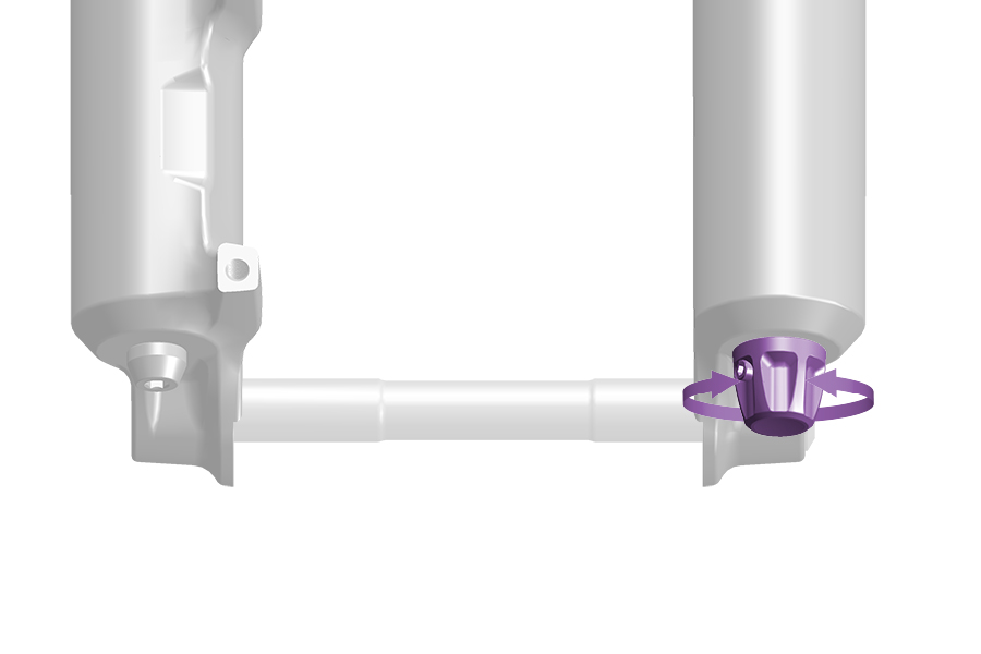
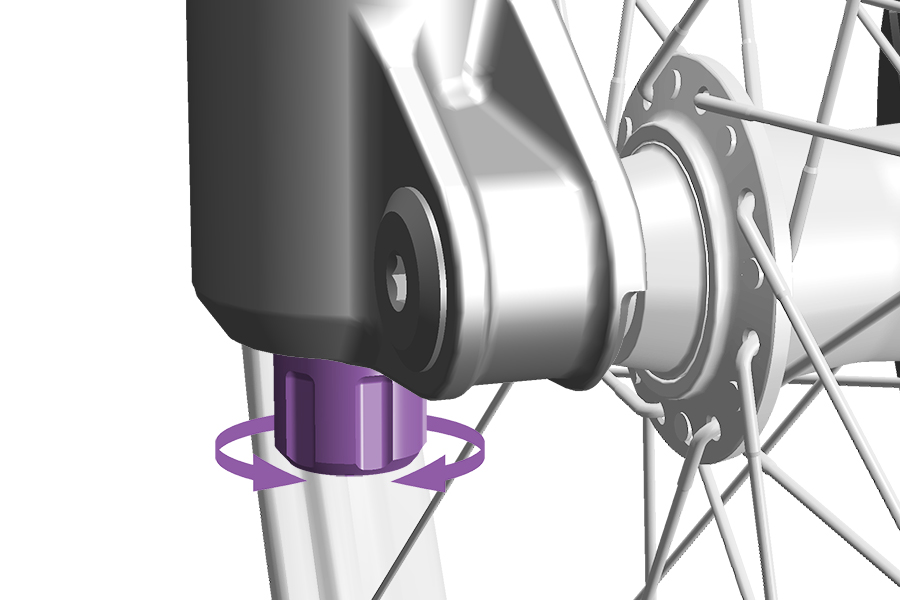
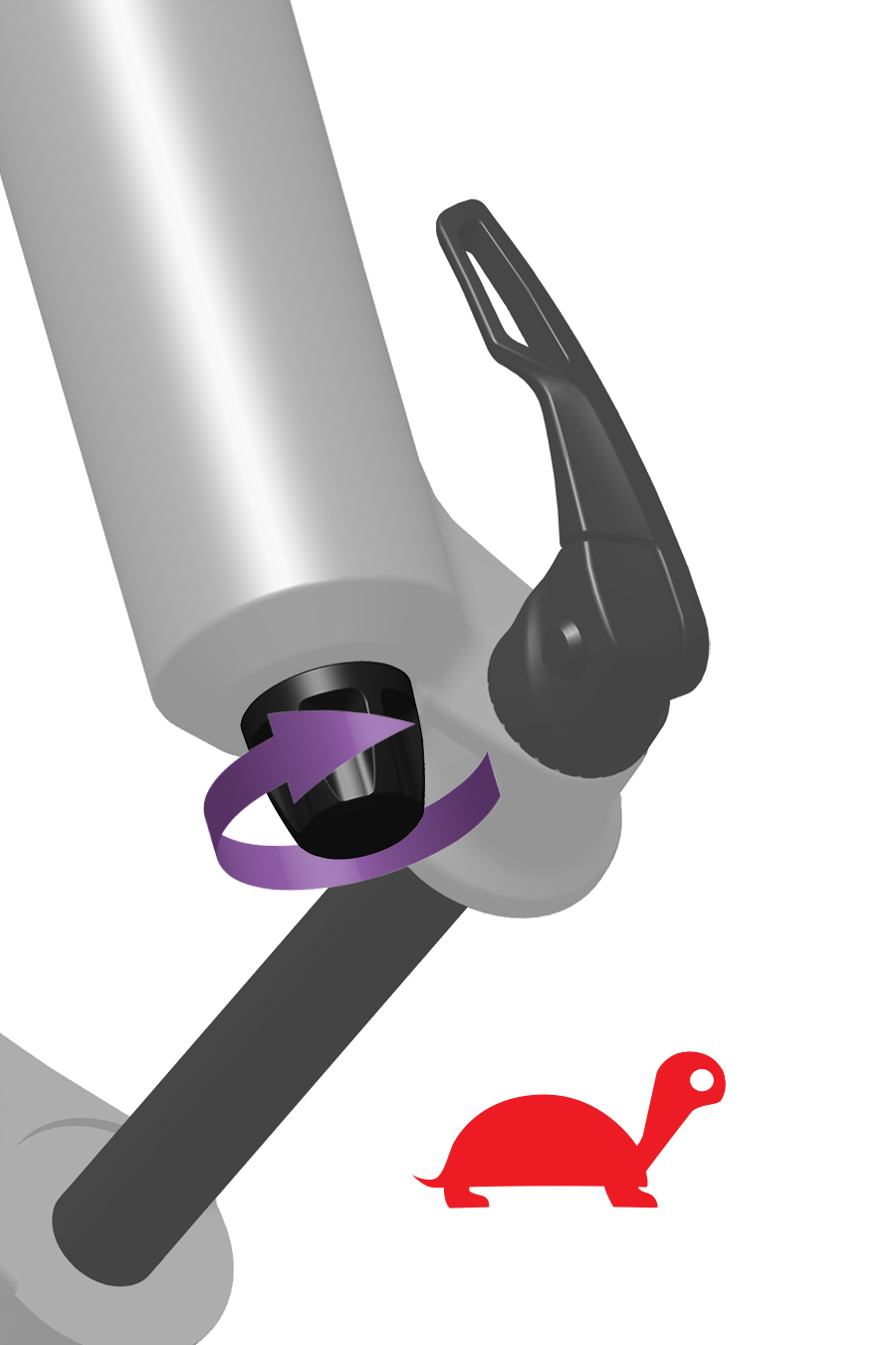
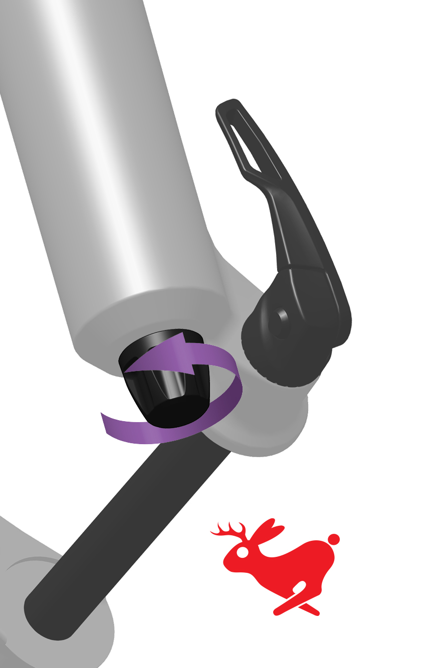
Rebound damping controls suspension fork extension/return speed which affects traction and control.
Optimal rebound damping allows the fork to extend at a controlled speed and maintain traction and control.
Rebound that is too fast allows the fork to extend too quickly which causes the wheel to bounce off of objects and the ground resulting in a 'pogo' effect.
Rebound that is too slow prevents the fork from extending quickly enough to regain contact with the ground or prepare for the next impact.
Rebound damping can be tuned to rider weight, spring rate and travel, as well as for terrain and rider preference.
As air pressure or spring rate increases, extension/return speed increases. To achieve the optimal setting, rebound damping may need to be increased when air pressure or spring rate increases.
For recommended rebound settings refer to RockShox Trailhead. After setting air pressure (DebonAir+) or sag, adjust the rebound damper, go for a test ride, and adjust again as preferred.
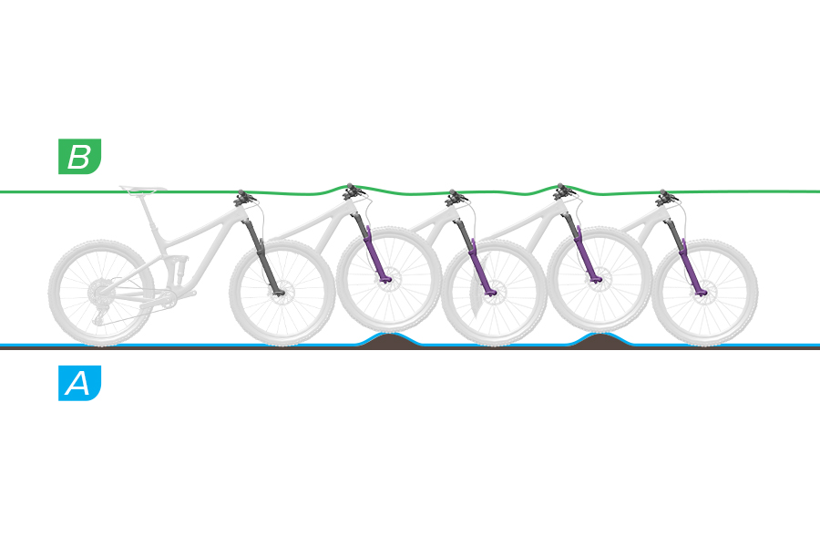
A: The fork rebounds at a controlled speed and the wheel maintains contact with the ground.
B: The fork crown, handlebars, and rider are more level with the ground over each bump. Suspension movement is predictable and controlled.
Adjustment: No adjustment is needed.
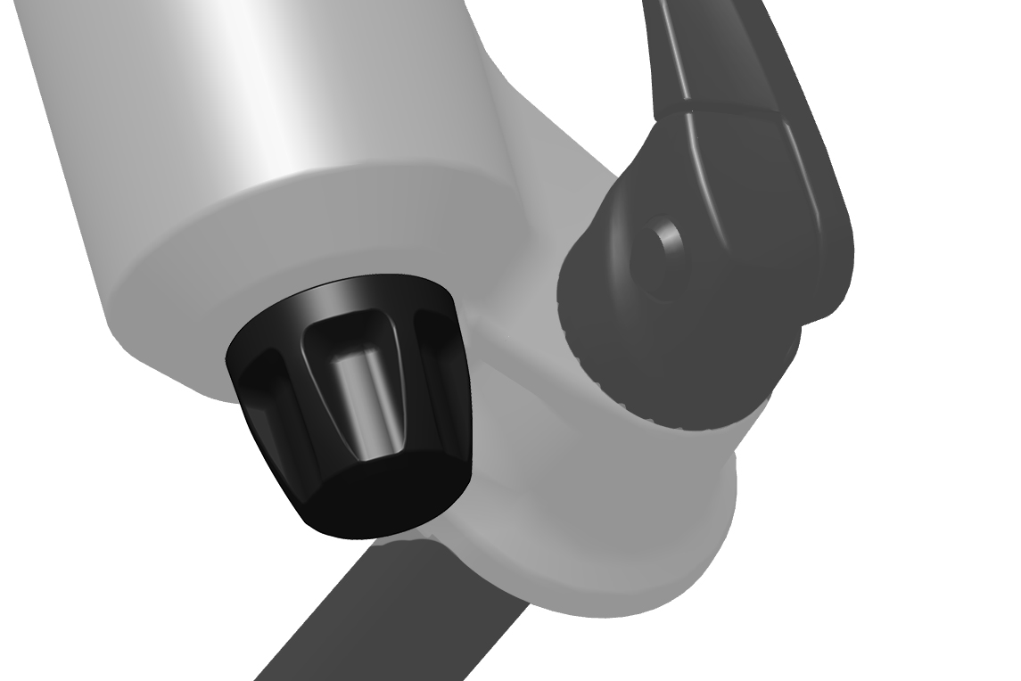
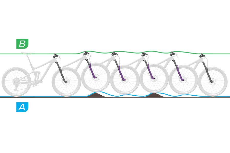
A: The fork rebounds too quickly causing a 'pogo' effect where the wheel bounces off of the terrain unpredictably. Traction and control are decreased.
B: The fork crown and handlebars are forced upward after the wheel bounces off of the ground. Rider weight may shift upward and back uncontrollably.
Adjustment: Turn the rebound adjuster clockwise to decrease rebound speed, and increase traction and control.
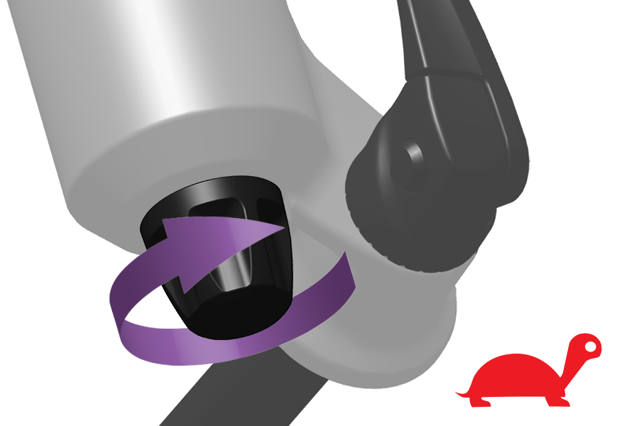
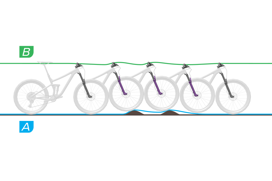
A: The fork does not extend quickly enough after absorbing a bump. The fork stays compressed through successive bumps, reducing travel and increasing impact firmness. Available travel, traction and control are decreased.
B: The fork stays in a compressed state which puts the crown and handlebars in a lowered position. Rider weight may shift forward at impact.
Adjustment: Turn the rebound adjuster knob counterclockwise to increase rebound speed and improve bump performance.
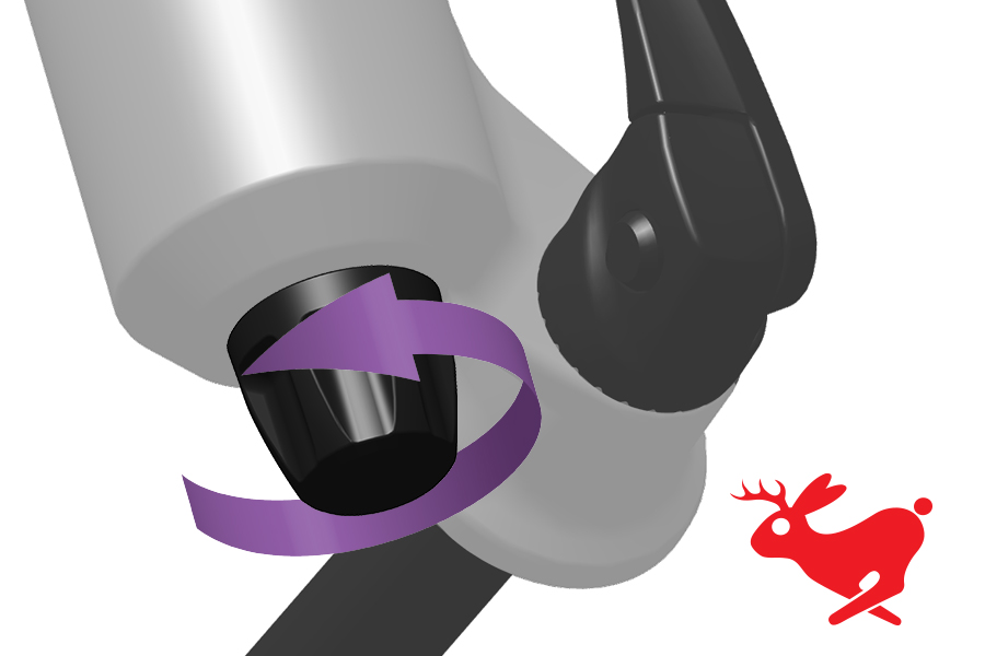
Rebound damping controls suspension rebound speed after compression.
Suspension rebound speed affects wheel contact with the ground, which affects control and efficiency. The shock should rebound quickly enough to maintain wheel traction without feeling 'bouncy'. Too much rebound damping will not allow the shock to rebound quickly enough for the next bump.
To increase rebound damping, and decrease rebound speed, rotate the knob clockwise.
To decrease rebound damping, and increase rebound speed, rotate the knob counterclockwise.
.jpg)
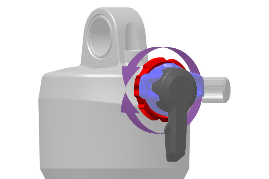
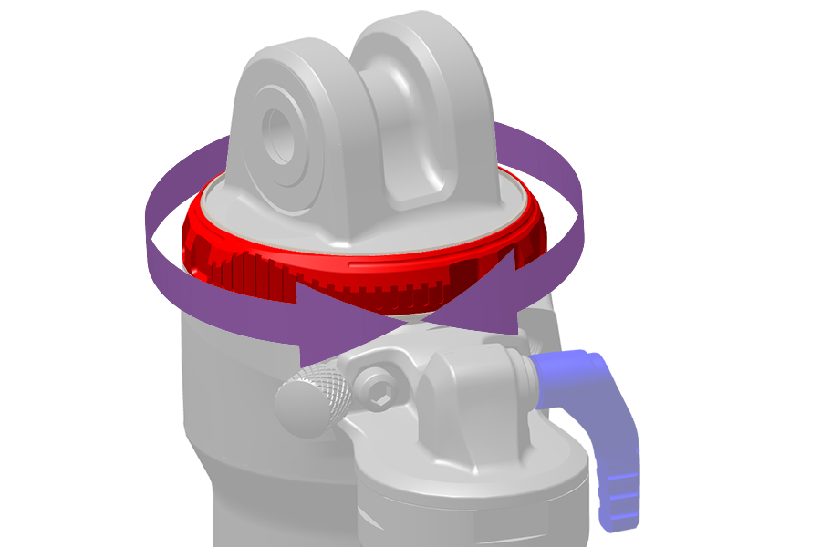
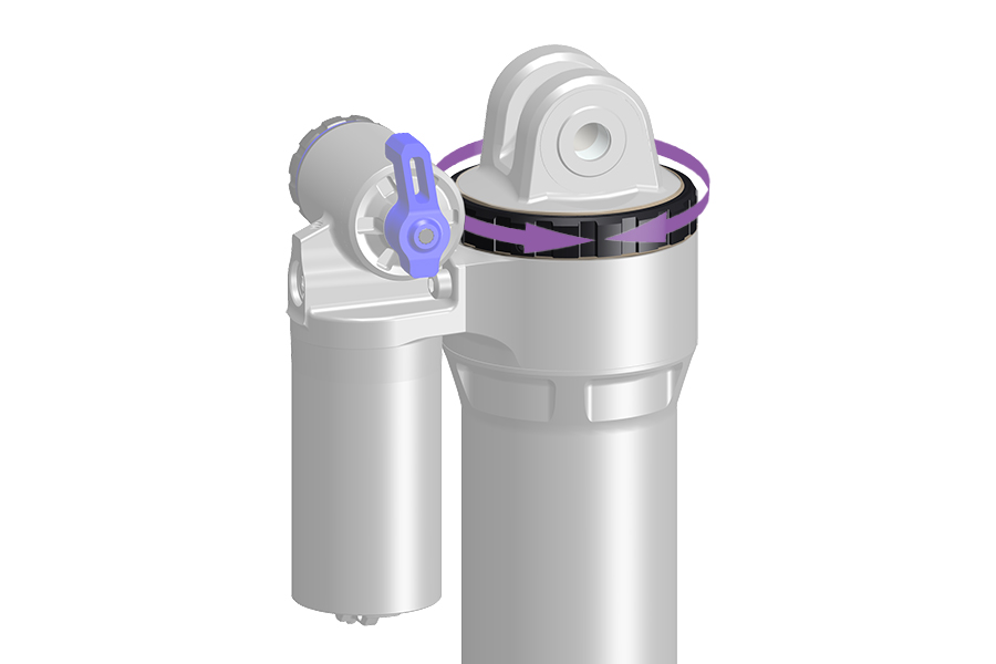
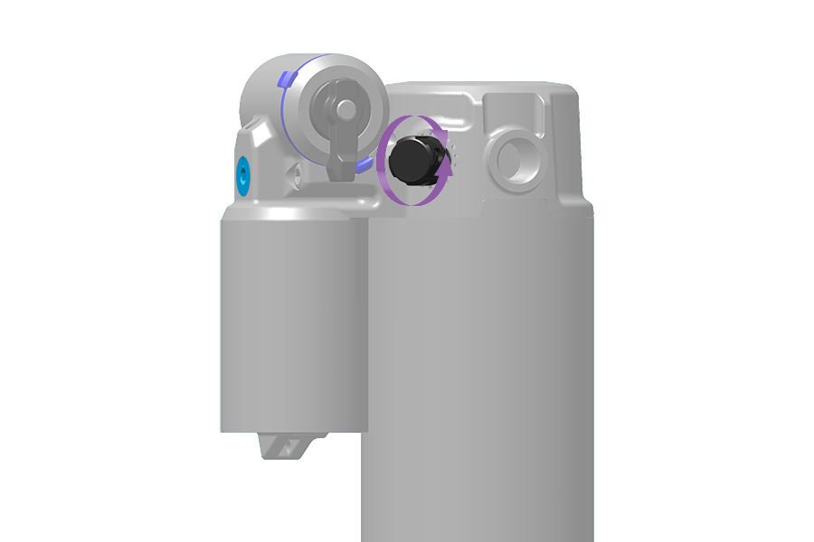
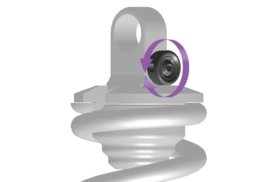
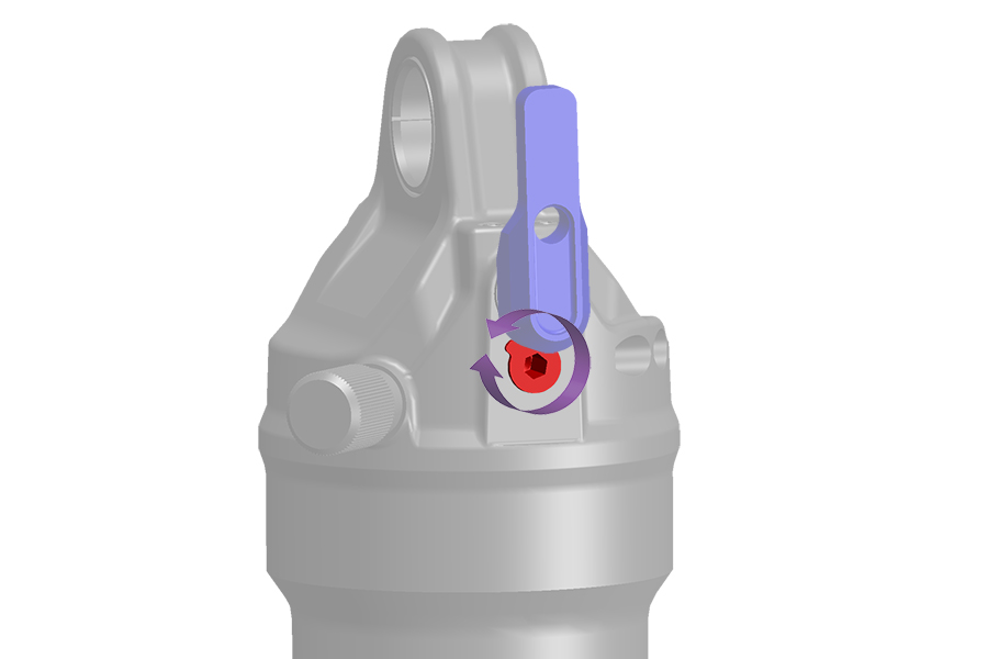
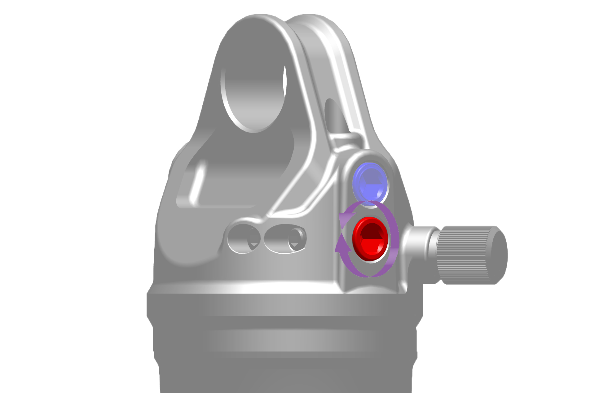
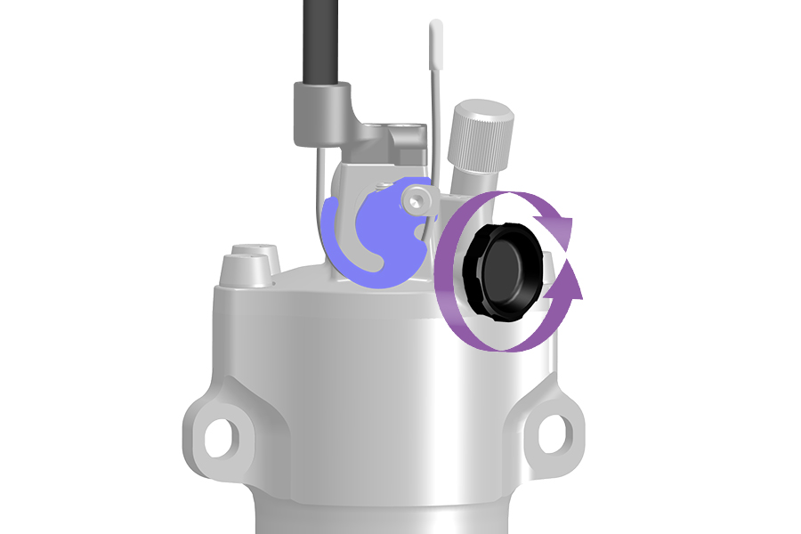
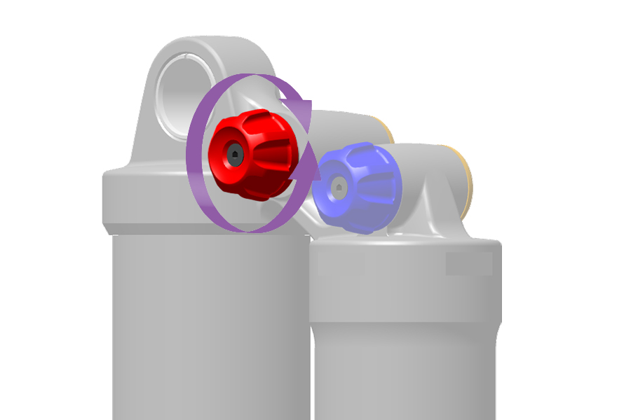
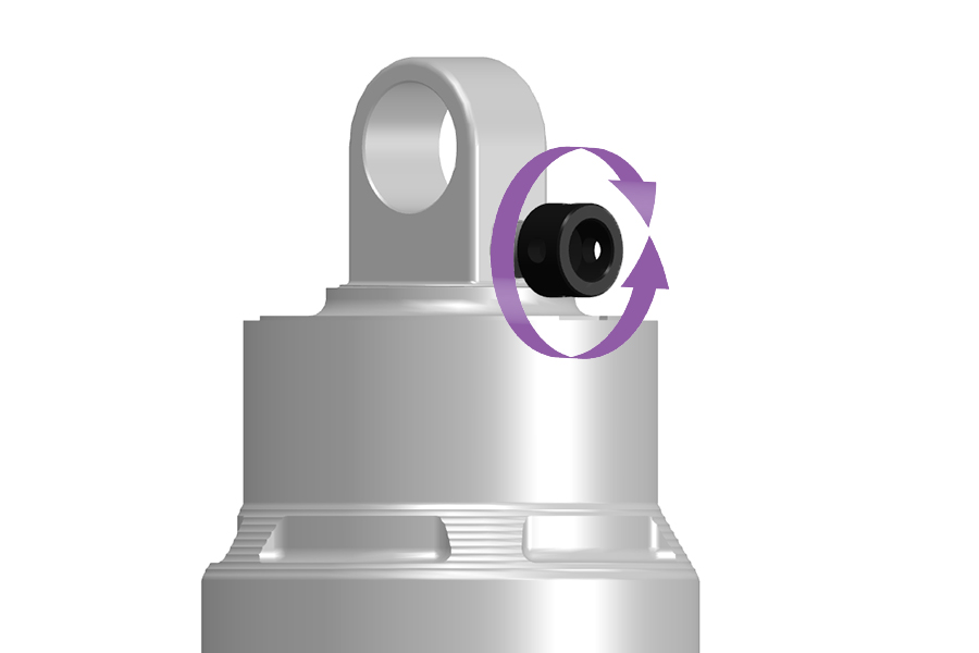
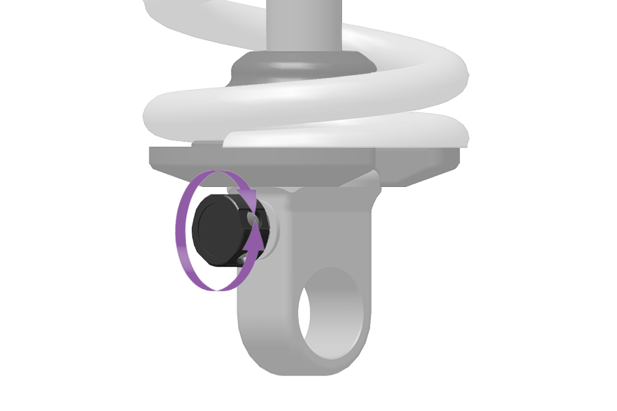
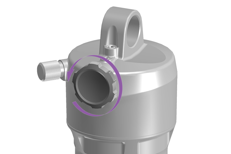
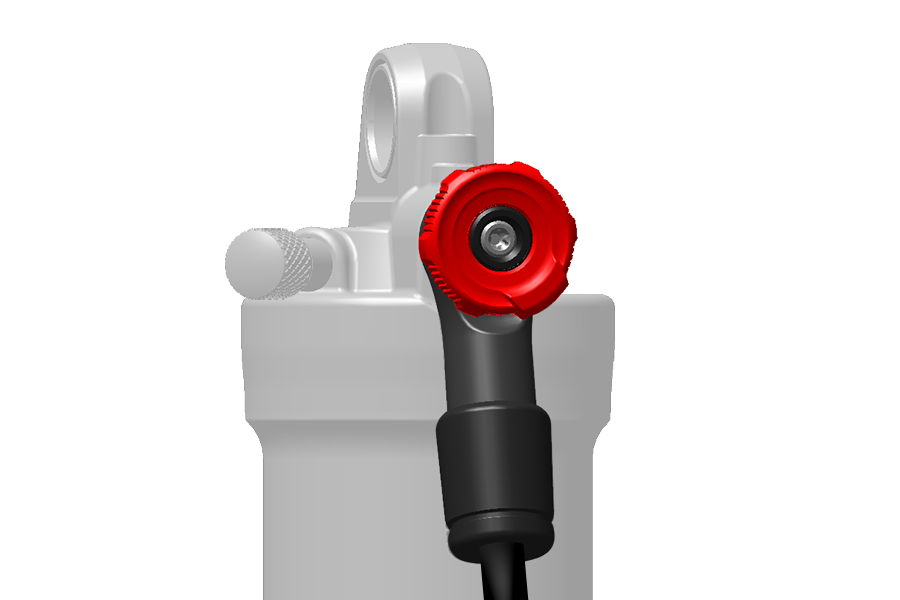
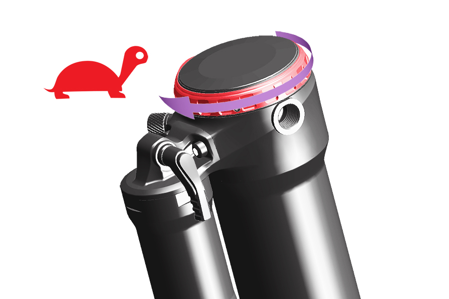
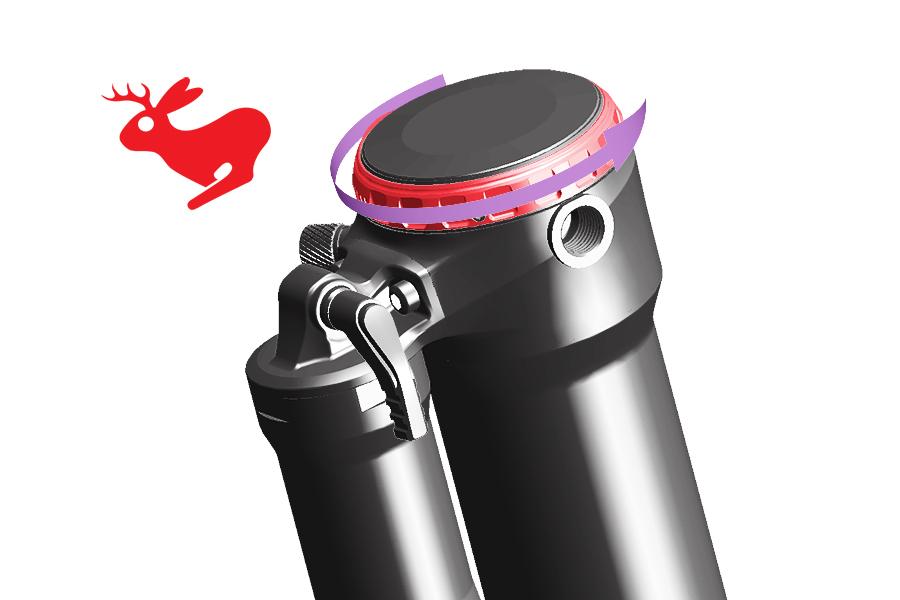
Rebound damping controls rear shock extension/return speed which affects traction and control.
Optimal rebound damping allows the shock to extend at a controlled speed, support the rider's weight through and after the bump, and maintain traction and control.
Rebound that is too fast causes the shock to extend too quickly after the shock compresses which can cause the bicycle and rider to bounce or pitch forward. This can result in loss of control and stability.
Rebound that is too slow prevents the shock from extending quickly enough to regain contact with the ground or prepare for the next impact. The shock remains in a more compressed state into the next bump which reduces available suspension travel and bump absorption.
Rebound damping can be tuned to rider weight, spring rate, and travel, as well as for terrain and rider preference.
As air pressure or spring rate increases, extension/return speed increases. To achieve the optimal setting, rebound damping may need to be increased when air pressure or spring rate increases. After setting sag, adjust the rebound damper, go for a ride, and adjust again as preferred.
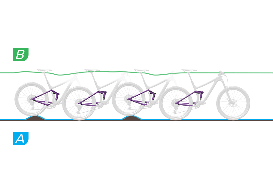
A. The shock rebounds at a controlled speed. The rear wheel does not bounce off the bump or ground and maintains contact with the ground.
B. The saddle rises slightly as the bump is absorbed, and drops slightly as the suspension compresses when the wheel contacts the ground after the bump. The shock rebounds in a controlled manner keeping the rider level with the ground as the next bump is absorbed. Suspension movement is predictable and controlled and the rider is not pitched upward or forward.
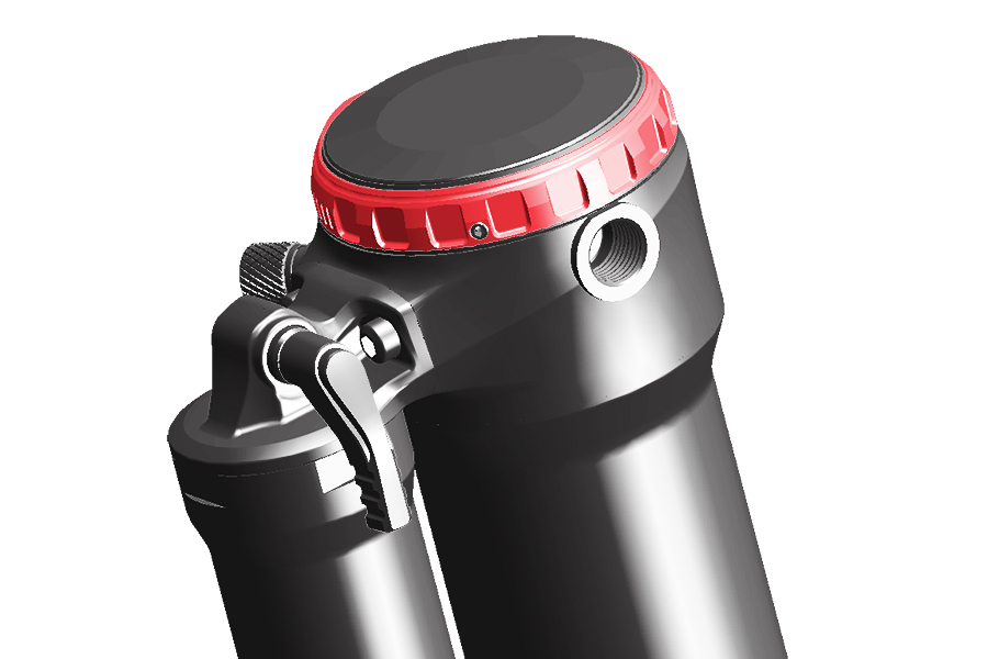
Adjustment: No adjustment is needed.
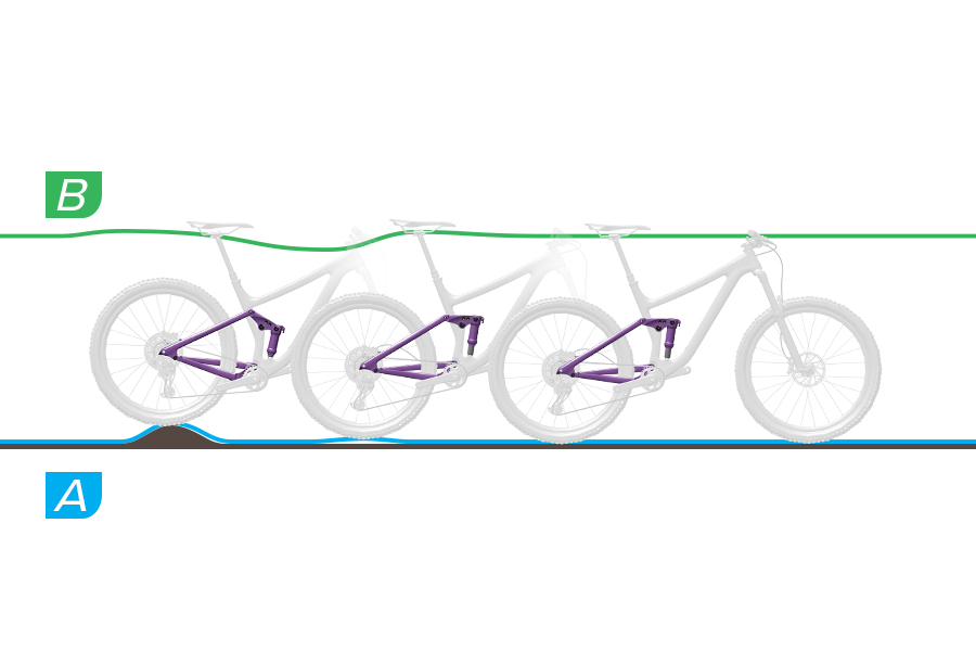
A. The shock rebounds too quickly causing a 'pogo' or bounce effect after the wheel hits a bump and lands back on the ground. Traction and control are decreased due to the uncontrolled speed with which the shock extends after compression.
B. The saddle and rider are forced upward after the wheel bounces off of a bump or the ground. Rider weight may shift upward and forward as the shock returns to full extension too quickly.
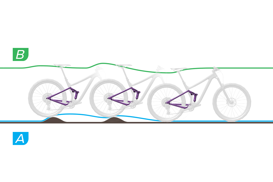
A. The shock does not extend quickly enough after absorbing a bump to reset for the next bump. The shock stays compressed through successive bumps, which reduces travel and contact with the ground, and increases firmness at the next impact. The rear wheel bounces off of the second bump because the shock does not extend quickly enough to regain contact with the ground and reset. Available travel and traction are decreased.
B. The shock stays in a compressed state after contacting the first bump. When the rear wheel contacts the second bump the saddle follows the path of the rear wheel rather than remaining level with the ground. Available travel and bump absorption are reduced causing instability and control through successive bumps.
High Speed Compression (HSC) damping controls compression speed during quick compression stroke scenarios such as large and square-edge bumps, and drops.
Increased HSC damping can prevent harsh compression stroke bottom out. Too much HSC damping can increase harshness over moderate size bumps.
To increase or decrease HSC damping, rotate the knob in the direction indicated on the knob.
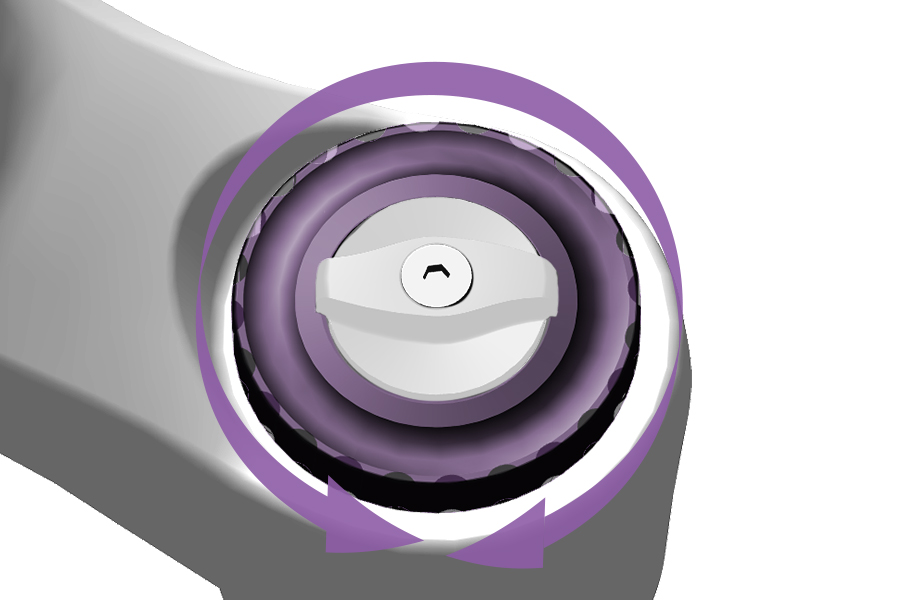
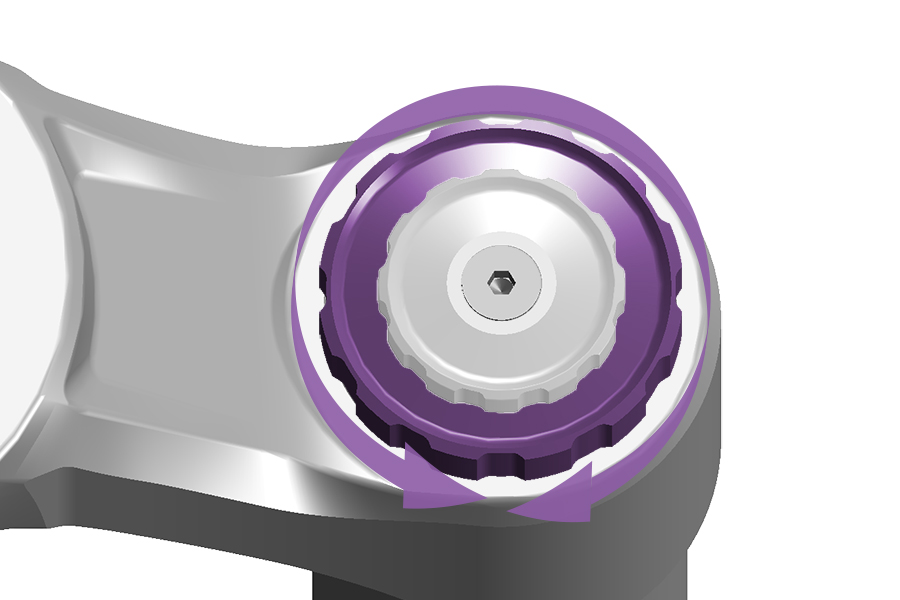
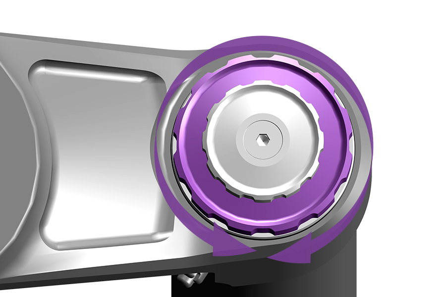
Start with the MIDDLE HSC setting and adjust as preferred.
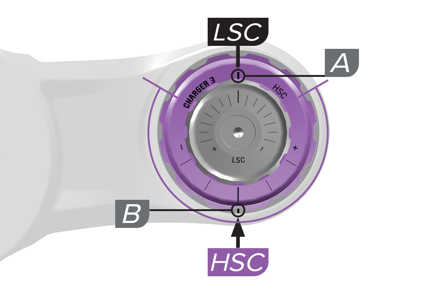
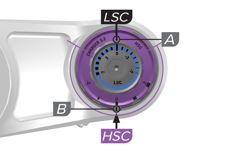
Charger 3, 3.1, 3.2 RC2: There are two etched lines that indicate LSC and HSC compression settings. The (A) LSC indicator line is etched on the large HSC knob. The (B) HSC indicator line is etched on a plate under the HSC knob.
Rotate the large HSC knob and align the adjustment setting line on the knob with the HSC indicator line on compression adjuster detent plate.
When the HSC knob is rotated, the LSC knob rotates with it, however the LSC setting does not change.
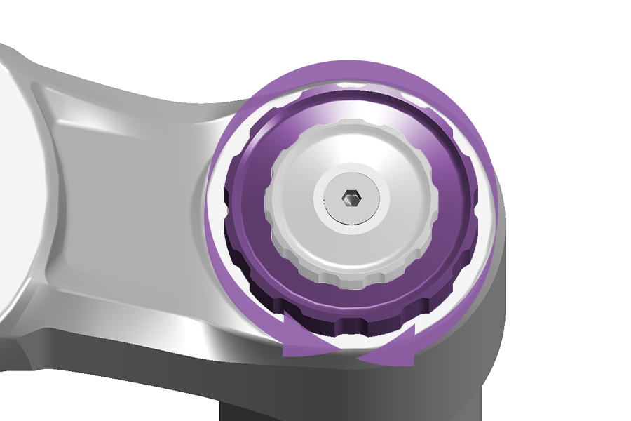
DebonAir+ Charger 3 RC2, Charger 3.1 RC2: Start with the middle HSC setting and adjust as preferred.
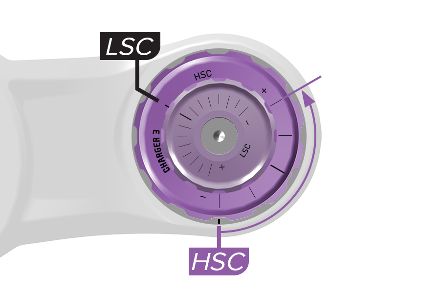
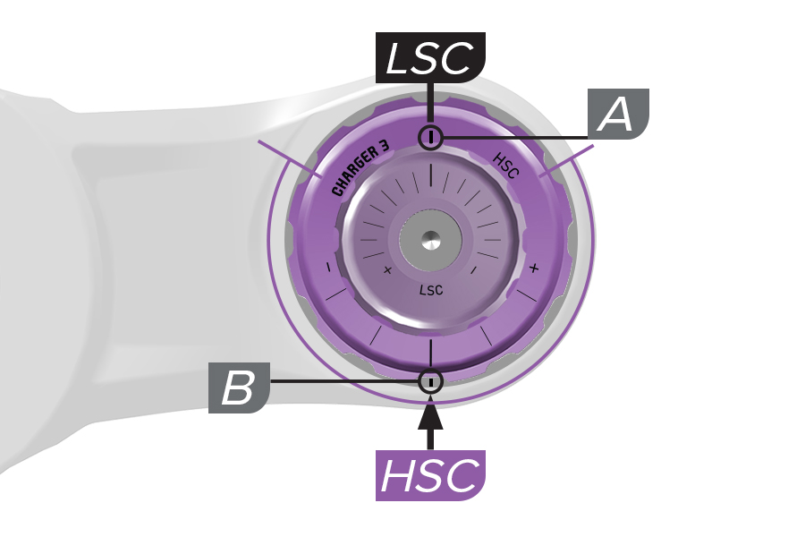
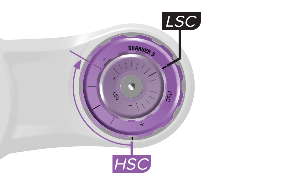
Charger 3 RC2, Charger 3.1 RC2: There are two etched lines that indicate LSC and HSC compression settings. The (A) LSC indicator line is etched on the large HSC knob. The (B) HSC indicator line is etched on a plate under the HSC knob.
Rotate the large HSC knob and align the adjustment setting line on the knob with the HSC indicator line on compression top cap.
When the HSC knob is rotated, the LSC knob rotates with it, however the LSC setting does not change.
High Speed Compression (HSC) damping controls compression speed during quick compression stroke scenarios such as large and square-edge bumps, and drops.
Increased HSC damping can prevent harsh compression stroke bottom out. Too much HSC damping can increase harshness over moderate size bumps.
To increase or decrease HSC damping, rotate the knob in the direction indicated on the knob.
DebonAir+ Charger 3 RC2: Start with the middle HSC setting and adjust as preferred.
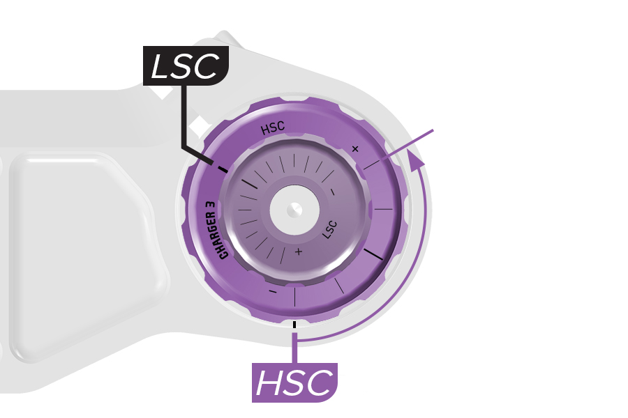
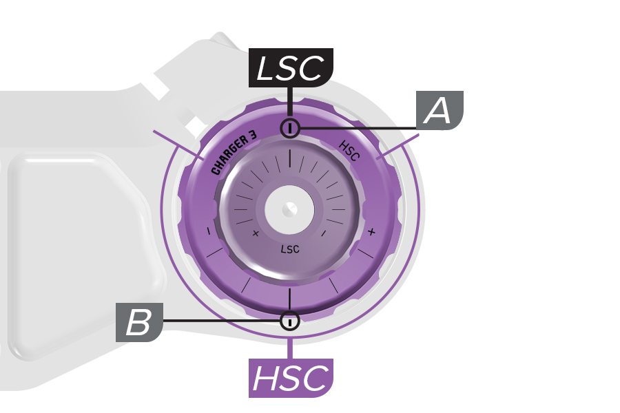
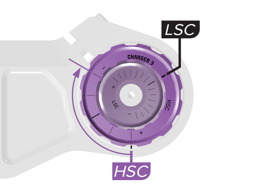
Charger 3 RC2: There are two etched lines that indicate LSC and HSC compression settings. The (A) LSC indicator line is etched on the large HSC knob. The (B) HSC indicator line is etched on a plate under the HSC knob. Rotate the large HSC knob and align the adjustment setting line on the knob with the HSC indicator line on compression top cap. When the HSC knob is rotated, the LSC knob rotates with it, however the LSC setting does not change.
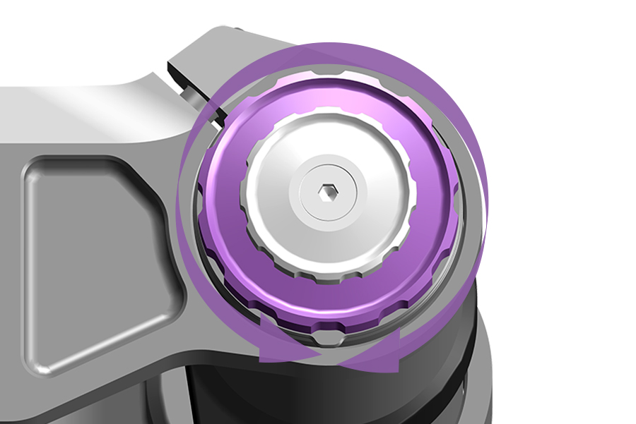
Start with the MIDDLE HSC setting and adjust as preferred.
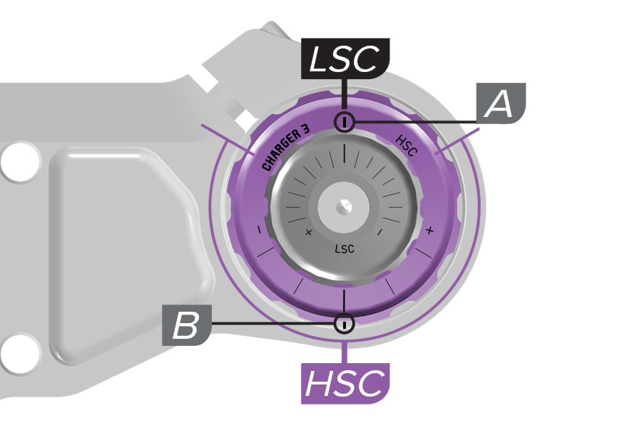
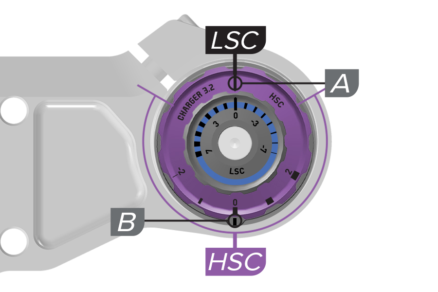
Charger 3, 3.1, 3.2 RC2: There are two etched lines that indicate LSC and HSC compression settings. The (A) LSC indicator line is etched on the large HSC knob. The (B) HSC indicator line is etched on a plate under the HSC knob.
Rotate the large HSC knob and align the adjustment setting line on the knob with the HSC indicator line on compression adjuster detent plate.
When the HSC knob is rotated, the LSC knob rotates with it, however the LSC setting does not change.
High Speed Compression (HSC) damping adjustment controls compression stroke speed, or the rate at which the fork compresses, during quick compression scenarios. HSC affects bump impact absorption and efficiency over large and square edge bumps, and down drops.
Bump size and shape, as well as riding speed, can affect compression stroke speed. Large or square edge/sharp bumps will cause the fork to compress suddenly and quickly. Impacts of any size and shape will compress quicker when impacted at increased riding speed.
Increased HSC damping: Suspension travel used on bumpier terrain may be limited and may vary depending on bump or drop size. This can prevent premature bottom out when riding over and through larger impacts. Suspension compression may feel more firm on bumpier terrain.
Decreased HSC damping: Allows the suspension to compress easily at higher compression stroke speeds. This may help the rider maintain speed and momentum on moderately bumpy terrain. May allow quick bottom out when riding quickly over and through larger bumps and drops. Suspension compression may feel less firm on bumpier terrain.
HSC damping adjustments have less effect during Low Speed Compression stroke scenarios. Rider weight shifts, transitions, cornering, more gradual impacts, and braking do not create enough force to enter the HSC damper's effective range of control.
Increase HSC damping to reduce High Speed Compression stroke speed on moderate to larger impacts and very aggressive terrain.
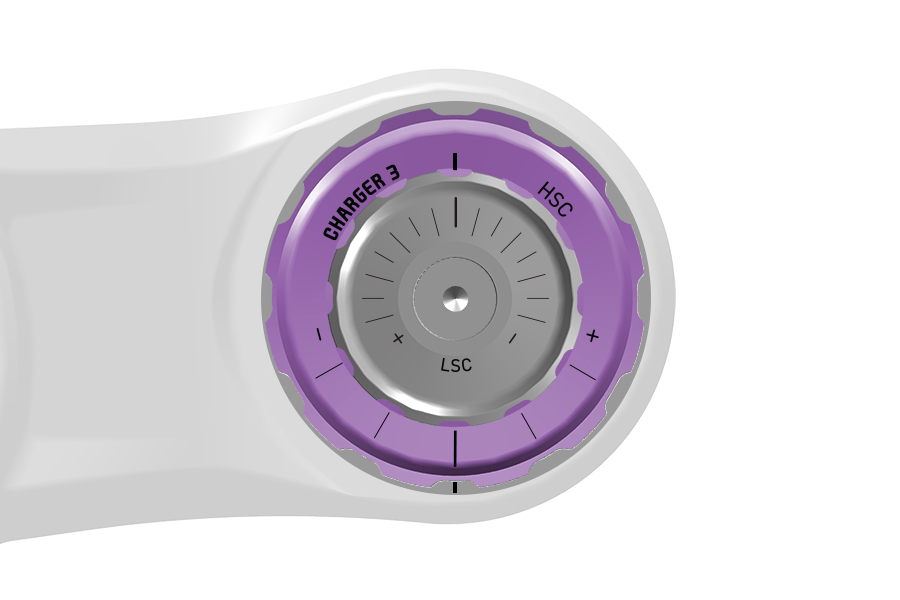
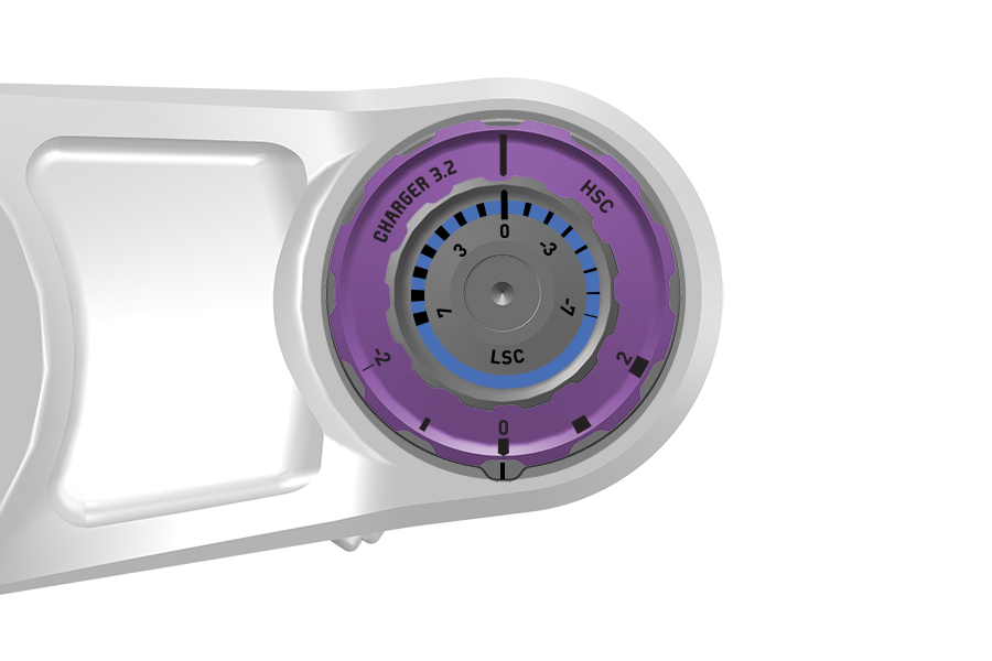
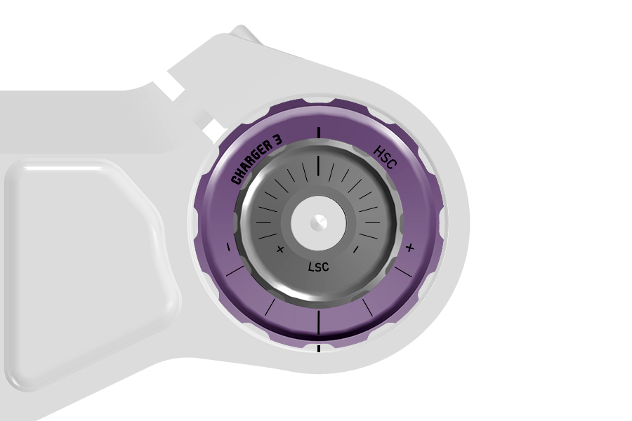
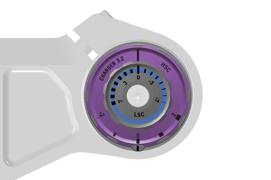
To increase (+) High Speed Compression damping (firm), turn the HSC adjuster knob clockwise.
To decrease (-) High Speed Compression damping (soft), turn the HSC adjuster knob adjuster counterclockwise.
DebonAir+ Charger 3 RC2, Charger 3.1 RC2: Start with the middle HSC setting and adjust as preferred.
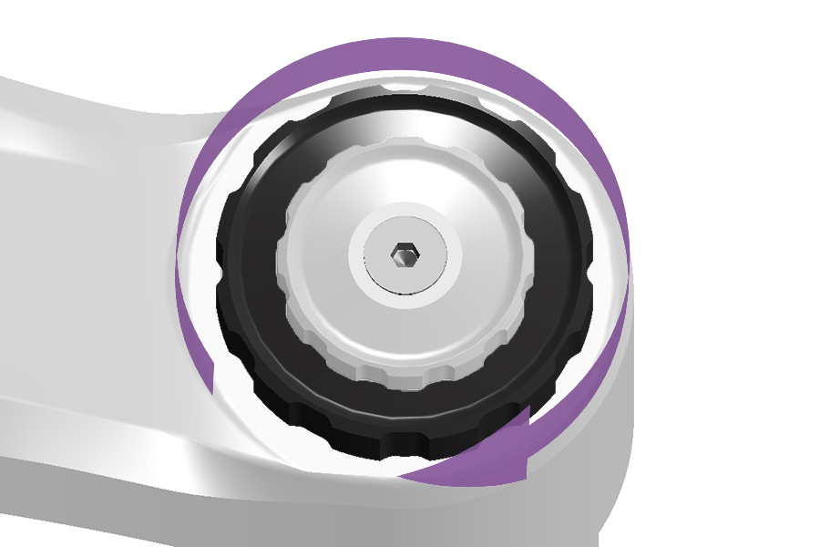
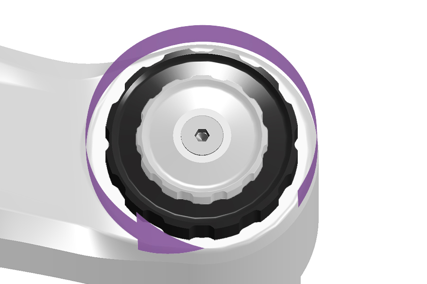
Adjustment: Rotate the HSC adjuster knob counter-clockwise to decrease compression damping and increase stroke speed.
Rotate the HSC adjuster clockwise to increase compression damping and decrease stroke speed.
Start with a mid setting and adjust as desired. Larger bumps and drops, and increased riding speed will typically allow for a firmer HSC setting.
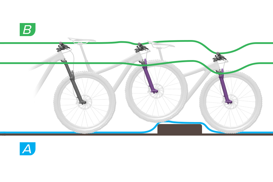
HSC Damping - Soft
A. The fork compresses through full travel quickly and freely. The fork can use most of its travel as impacts are fully absorbed.
B. The fork crown and handlebar drop quickly at full compression, or fork bottom out.
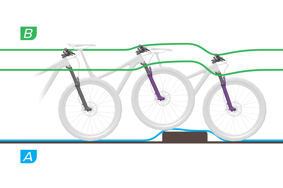
HSC Damping - Mid
A. The fork can compress through its effective travel, absorbing the impact in a controlled manner. Use of full travel may depend on rider speed and bump size.
B. The fork crown and handlebar rise moderately at bump impact, and drop moderately after the drop.
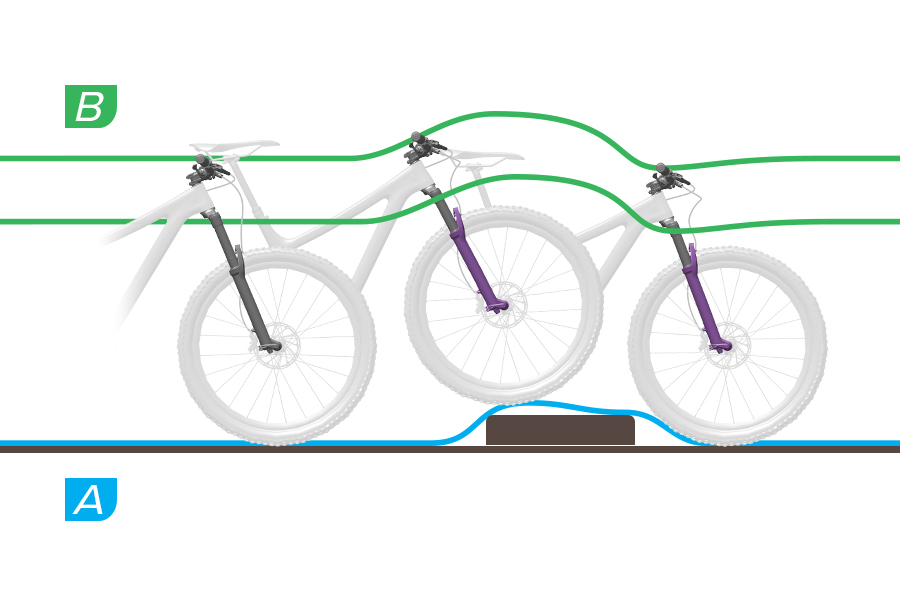
HSC Damping - Firm
A. The fork can resist compressing and impact force may be transmitted to the rider. The fork compresses partially and does not bottom out. Use of full travel depends on rider speed and bump size.
B. The fork crown and handlebar are suddenly forced up at bump impact, and drop minimally after the drop as the fork resists compressing.
High Speed Compression (HSC) damping controls compression speed during quick compression stroke scenarios such as large and square-edge bumps, and drops. Increased HSC damping can prevent harsh compression stroke bottom out. Too much HSC damping can increase harshness over moderate size bumps. To increase or decrease HSC damping, rotate the knob in the direction indicated on the knob.
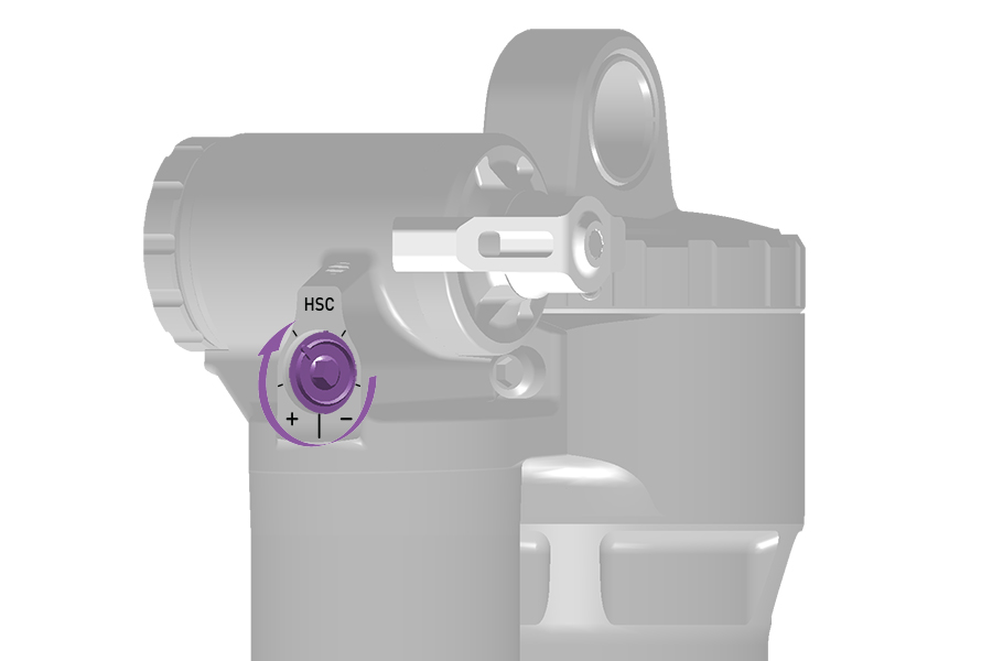
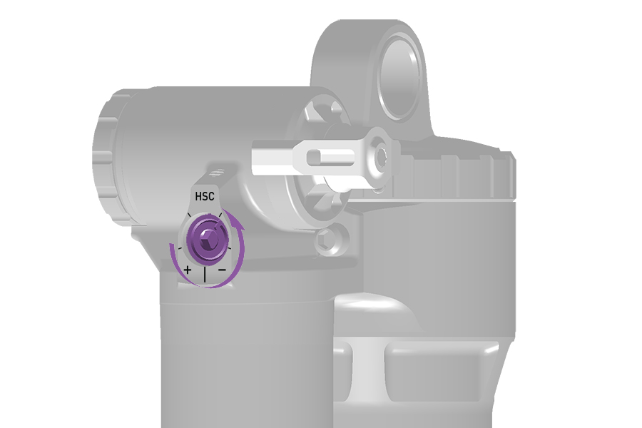
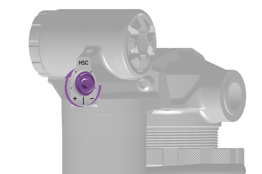
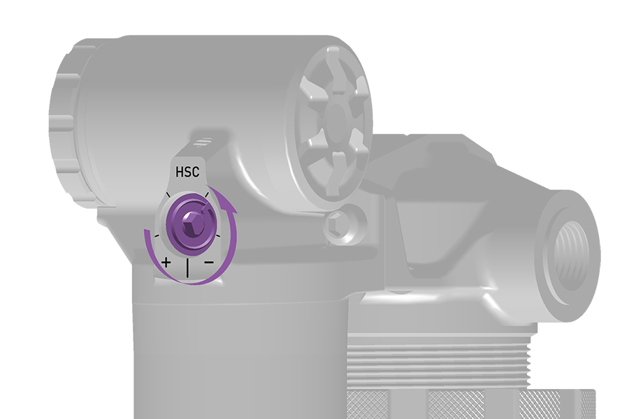
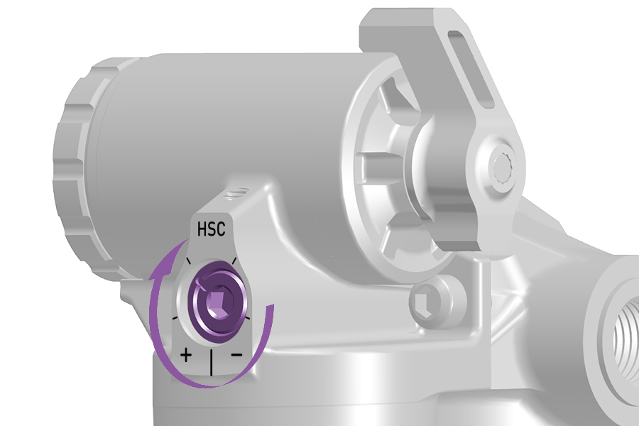
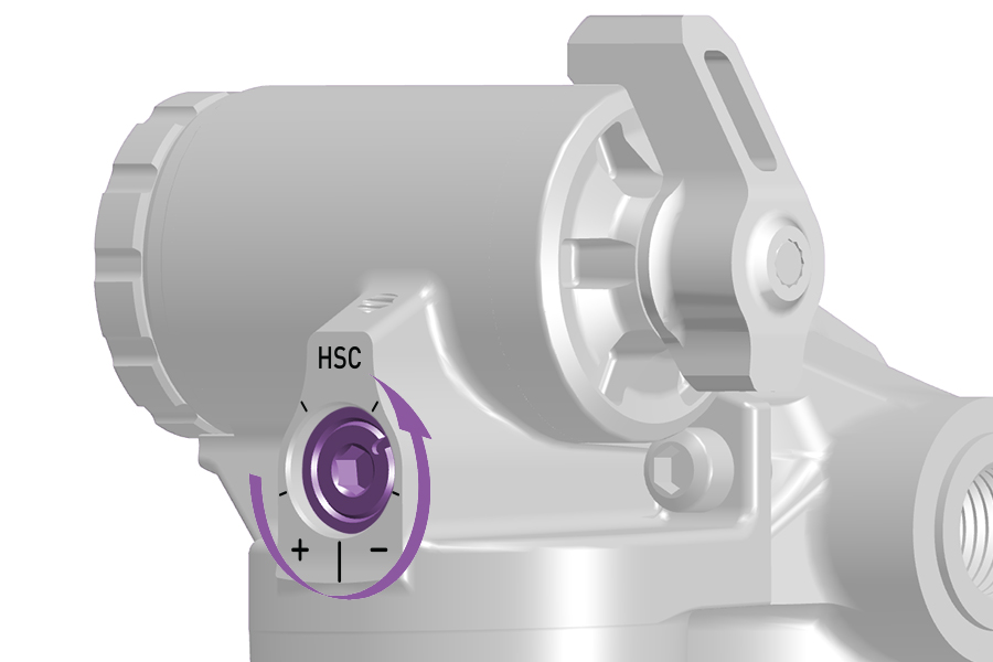
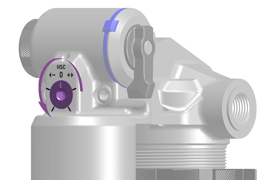
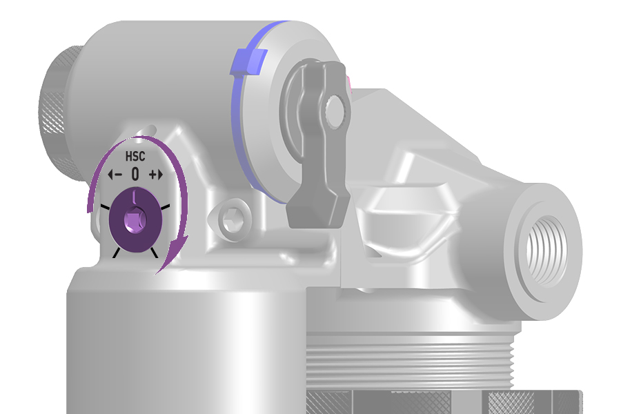
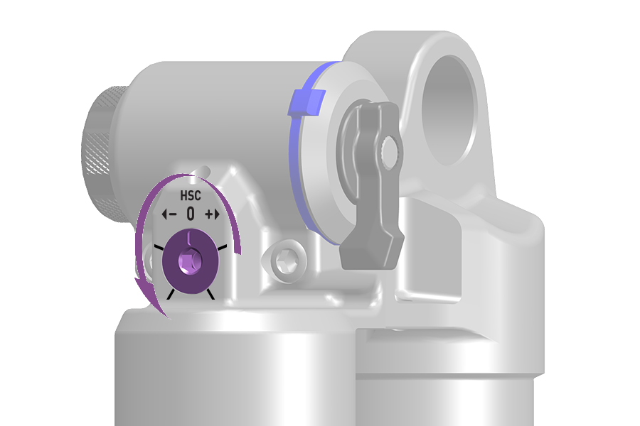
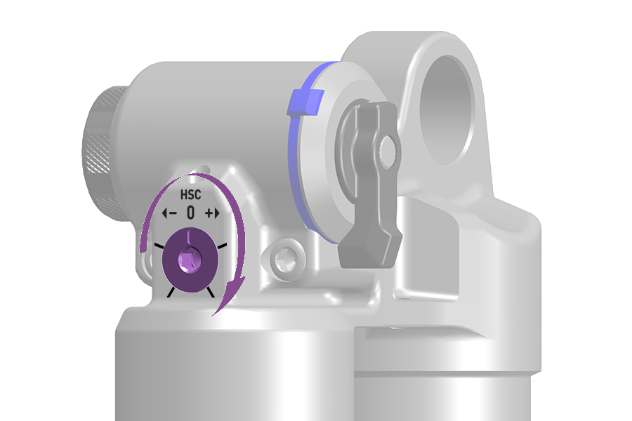
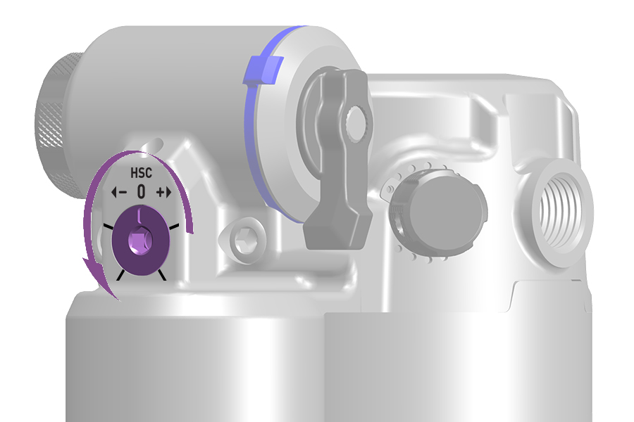
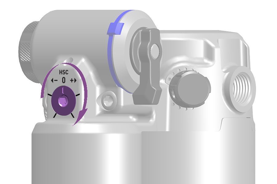
High Speed Compression (HSC) damping adjustment controls compression stroke speed, or the rate at which the rear shock compresses, during quick compression scenarios. HSC affects bump impact absorption and efficiency over large and square edge bumps, and down drops.
Bump size and shape, as well as riding speed, can affect compression stroke speed. Large or square edge/sharp bumps will cause the rear shock to compress suddenly and quickly. Impacts of any size and shape will compress quicker when impacted at increased riding speed.
Increased HSC damping:
Suspension travel used on bumpier terrain may be limited and may vary depending on bump or drop size. This can prevent premature bottom out when riding over and through larger impacts.
Suspension compression may feel more firm on bumpier terrain.
Decreased HSC damping:
Allows the suspension to compress easily at higher compression stroke speeds. This may help the rider maintain speed and momentum on moderately bumpy terrain.
May allow quick bottom out when riding quickly over and through larger bumps and drops.
Suspension compression may feel less firm on bumpier terrain.
HSC damping adjustments have less effect during Low Speed Compression (LSC) stroke scenarios. Rider weight shifts, transitions, cornering, more gradual impacts, and braking do not create enough force to enter the HSC damper's effective range of control. Increase HSC damping to reduce High Speed Compression stroke speed on moderate to larger impacts and very aggressive terrain.
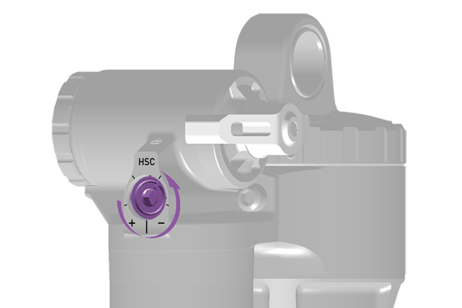
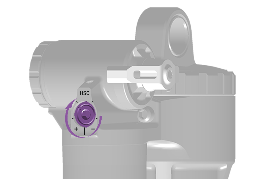
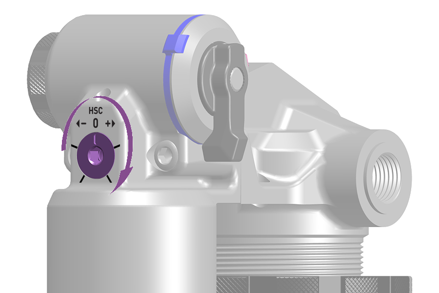
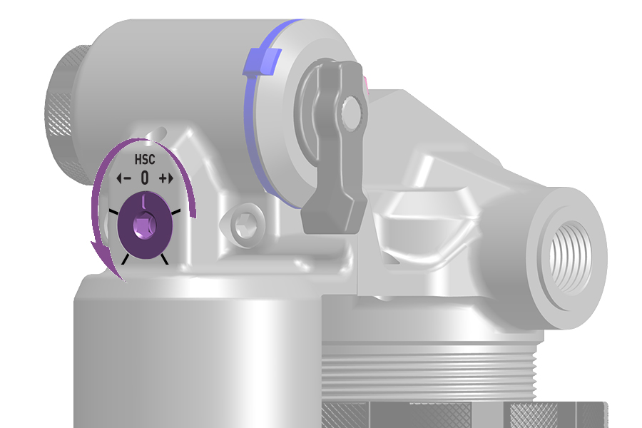
Adjustment: Rotate the HSC adjuster counterclockwise (−) to decrease high speed compression damping and increase stroke speed.
Rotate the HSC adjuster clockwise (+) to increase high speed compression damping and decrease stroke speed.
Start with a mid setting and adjust as desired. Larger bumps and drops, and increased riding speed will typically allow for a firmer HSC setting.
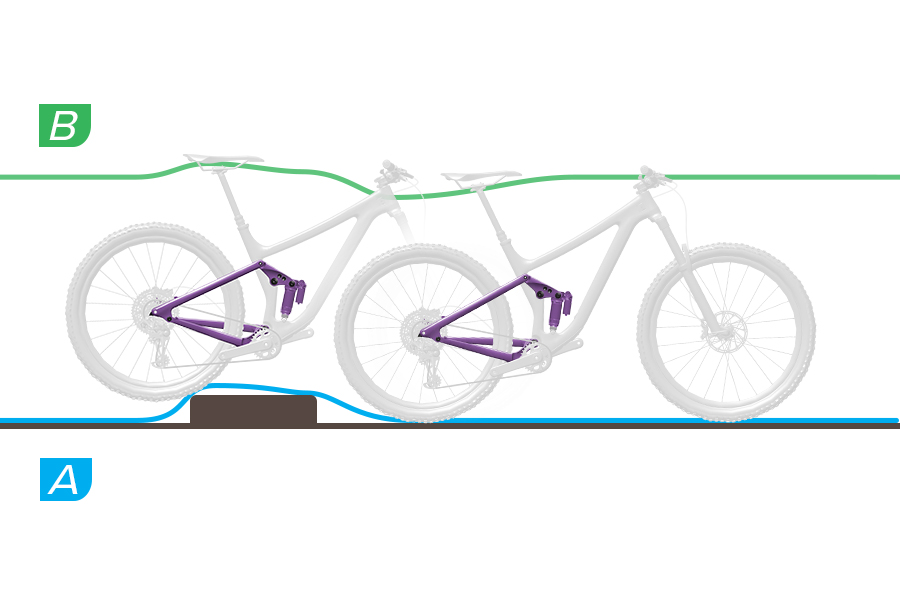
HSC Damping - Soft
A. The shock compresses through full travel quickly and freely. The shock can use most of its travel as impacts are fully absorbed at most rider speeds.
B. The shock bottoms out quickly and the rear wheel rises quickly at impact and drop.
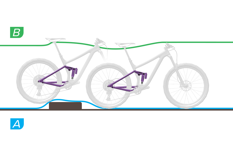
HSC Damping - Mid
A. The shock can compress through its effective travel, absorbing the impact in a controlled manner. Use of full travel may depend on rider speed and bump size.
B. The shock compresses and absorbs the impact and drop in a controlled manner, with mid-stroke support.
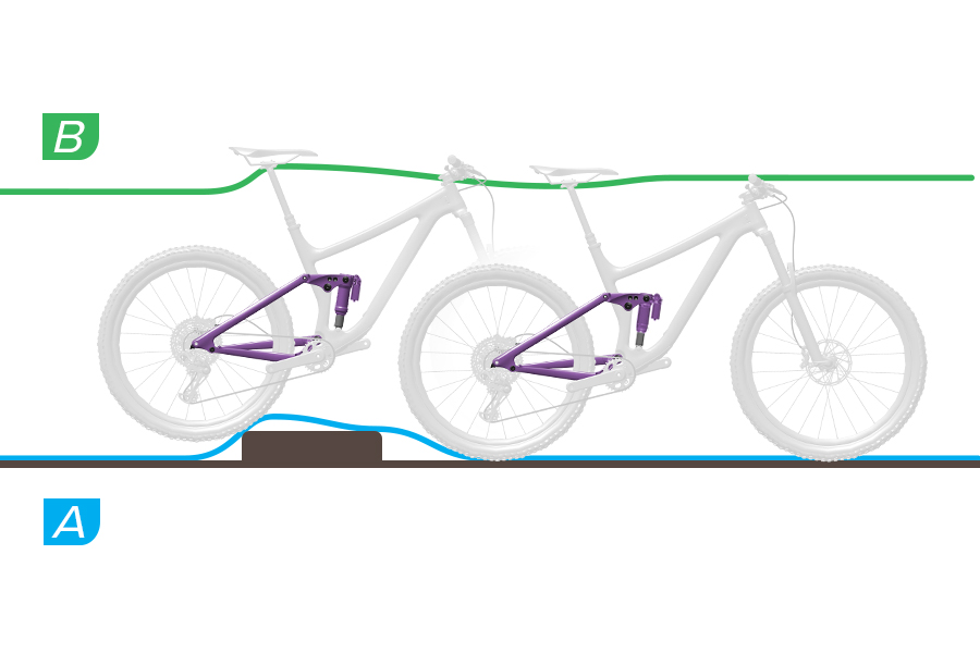
HSC Damping - Firm
A. The shock can resist compressing and impact force may be transmitted to the rider. The fork compresses partially and does not bottom out. Use of full travel depends on rider speed and bump size.
B. The shock resists compressing at impact and drop, and the rear wheel deflects upward and lands harshly.
Low Speed Compression (LSC) damping controls suspension compression stroke speed during slow compression stroke scenarios such as rider weight shifts, transitions, cornering, low impact bumps, and braking.
Too much LSC damping makes the suspension feel too firm over bumps.
To increase or decrease LSC damping, rotate the knob in the direction indicated on the knob.
Flight Attendant: Refer to the Flight Attendant User Manual for Low Speed Compression (LSC) details and procedures.
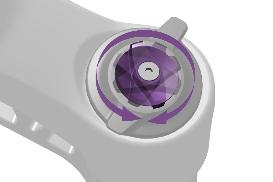
To increase or decrease LSC damping, rotate the knob in the direction indicated on the knob.
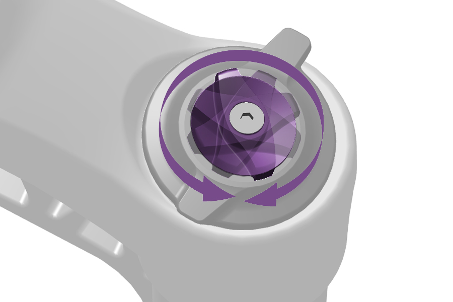
To increase or decrease LSC damping, rotate the knob in the direction indicated on the knob.
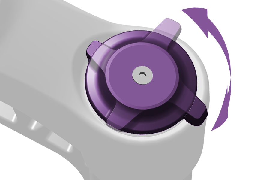
To increase or decrease LSC damping, rotate the knob in the direction indicated on the knob.
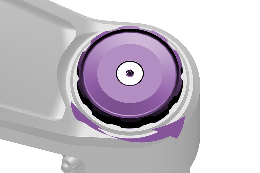
To increase or decrease LSC damping, rotate the knob in the direction indicated on the knob.
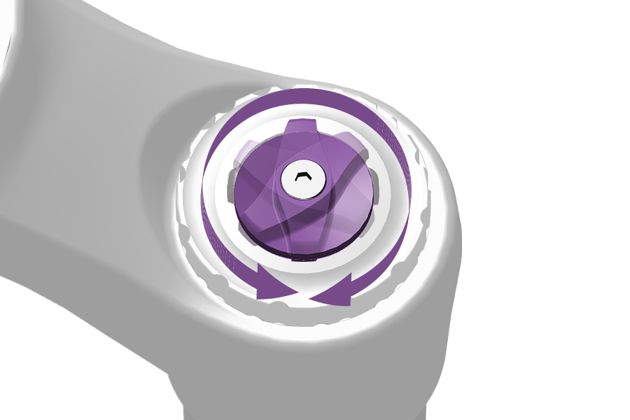
To increase or decrease LSC damping, rotate the knob in the direction indicated on the knob.
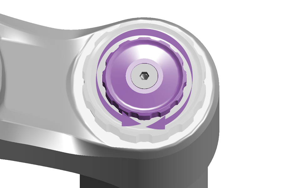
DebonAir+ Charger 3 RC2, Charger 3.1 RC2: Start with the middle LSC setting and adjust as preferred.
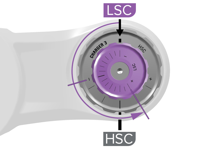
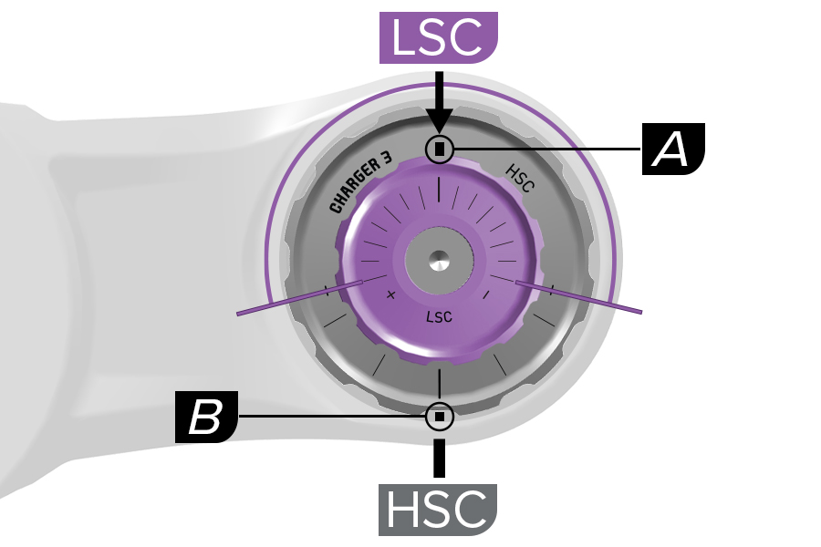
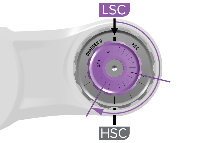
Charger 3 RC2, Charger 3.1 RC2: There are two etched lines that indicate LSC and HSC compression settings. The (A) LSC indicator line is etched on the large HSC knob. The (B) HSC indicator line is etched on a plate under the HSC knob.
The small LSC knob rotates independently of the HSC knob. Rotate and align the LSC knob adjustment setting line with the LSC indicator line on the HSC knob. The HSC setting does not change when the LSC knob is rotated.
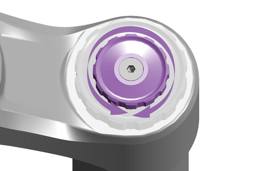
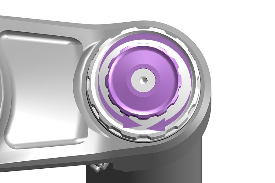
Start with the MIDDLE LSC setting and adjust as preferred.
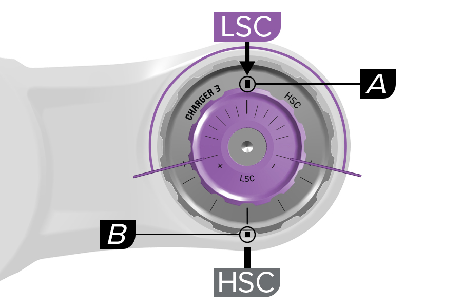
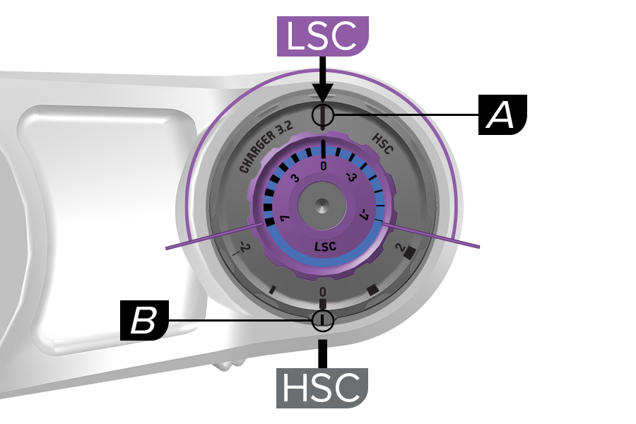
Charger 3, 3.1, 3.2 RC2: There are two etched lines that indicate LSC and HSC compression settings. The (A) LSC indicator line is etched on the large HSC knob. The (B) HSC indicator line is etched on a plate under the HSC knob.
The small LSC knob rotates independently of the HSC knob. Rotate and align the LSC knob adjustment setting line with the LSC indicator line on the HSC knob. The HSC setting does not change when the LSC knob is rotated.
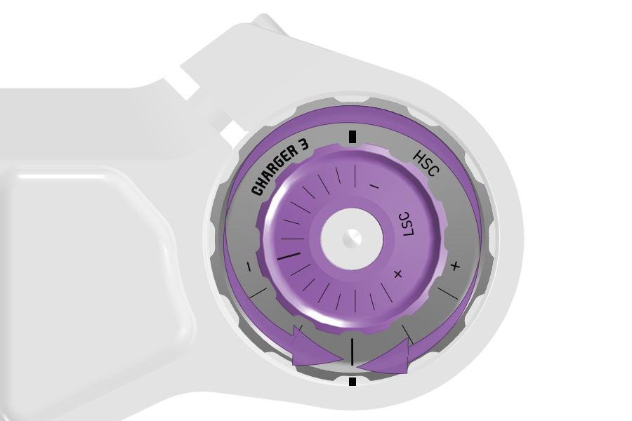
DebonAir+ Charger 3 RC2: Start with the middle LSC setting and adjust as preferred.
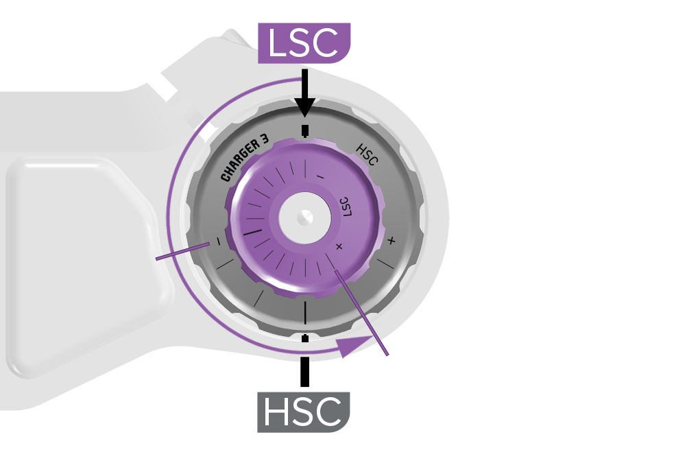
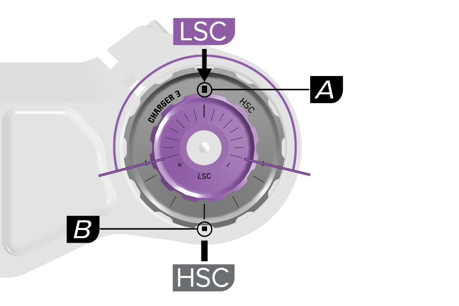
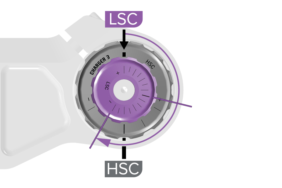
Charger 3 RC2: There are two etched lines that indicate LSC and HSC compression settings. The (A) LSC indicator line is etched on the large HSC knob. The (B) HSC indicator line is etched on a plate under the HSC knob.
The small LSC knob rotates independently of the HSC knob. Rotate and align the LSC knob adjustment setting line with the LSC indicator line on the HSC knob. The HSC setting does not change when the LSC knob is rotated.
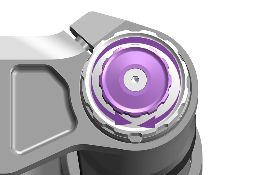
Start with the MIDDLE LSC setting and adjust as preferred.
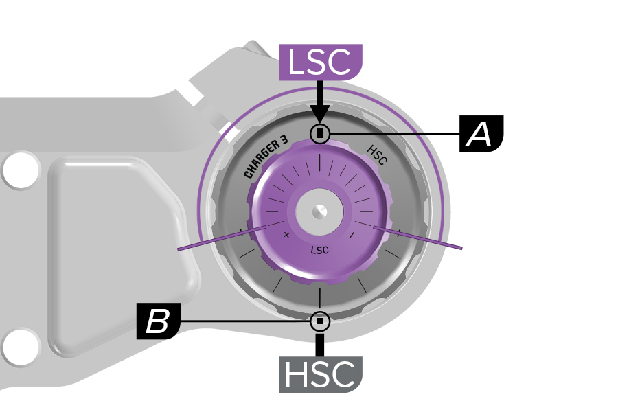
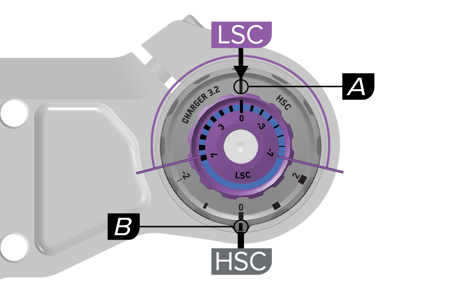
Charger 3, 3.1, 3.2 RC2: There are two etched lines that indicate LSC and HSC compression settings. The (A) LSC indicator line is etched on the large HSC knob. The (B) HSC indicator line is etched on a plate under the HSC knob.
The small LSC knob rotates independently of the HSC knob. Rotate and align the LSC knob adjustment setting line with the LSC indicator line on the HSC knob. The HSC setting does not change when the LSC knob is rotated.
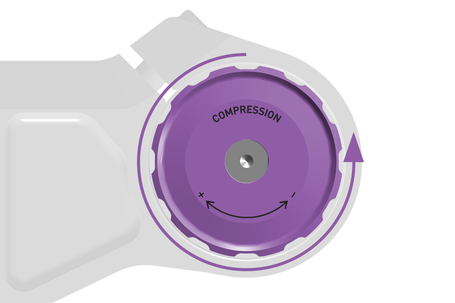
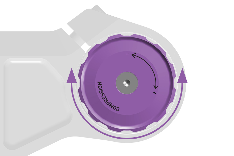
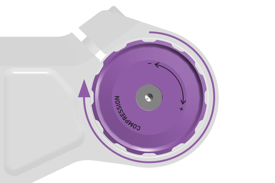
Charger 3 RC:
Rotate the LSC knob counterclockwise until it stops to adjust to the full open setting.
Rotate the LSC knob clockwise until it stops to adjust to the full closed setting.
Rotate the LSC knob seven clicks, from full clockwise or full counterclockwise, to the middle setting.
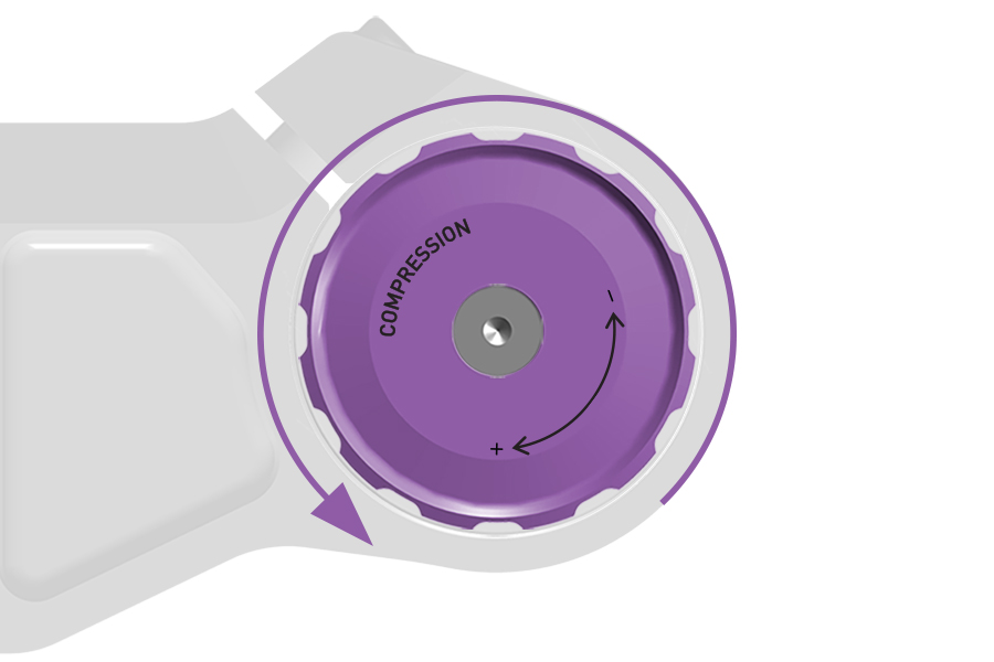
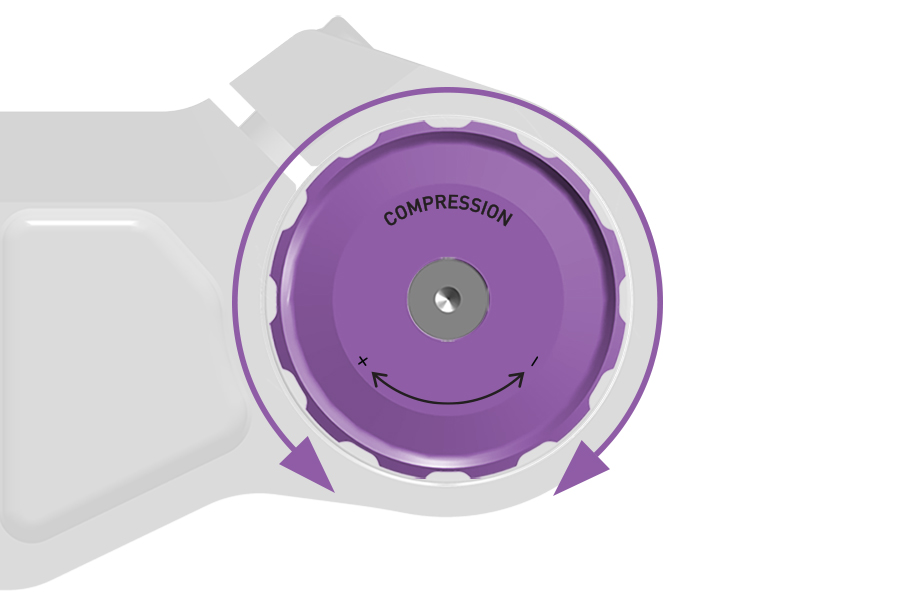
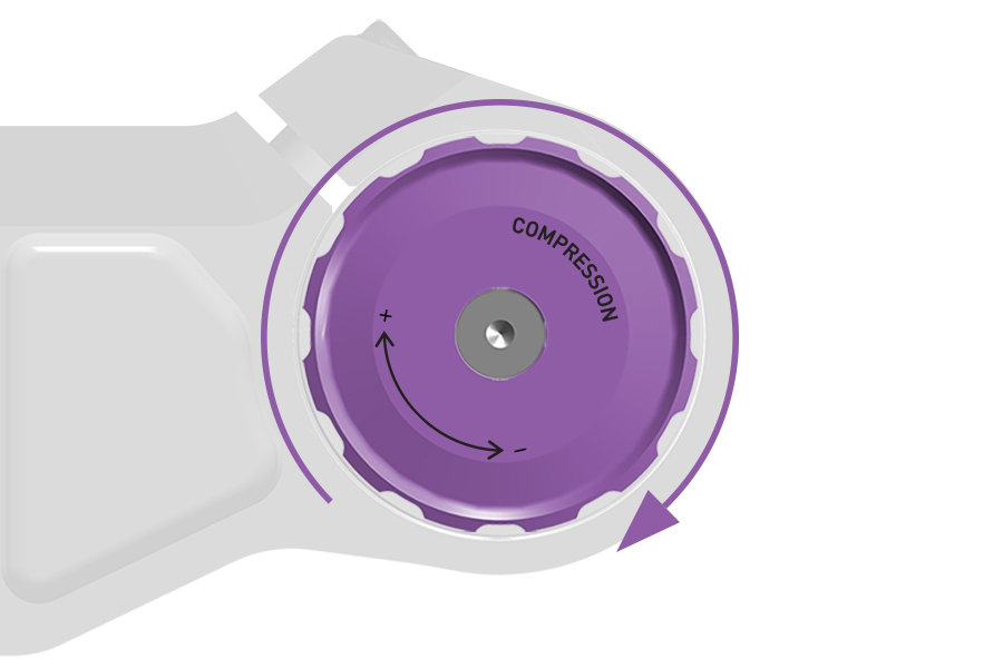
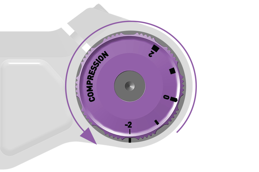
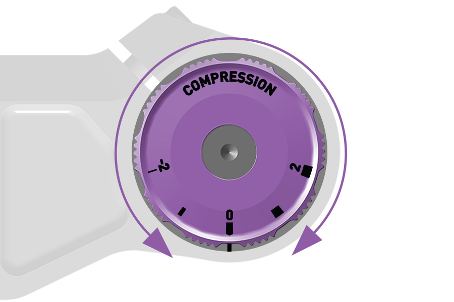
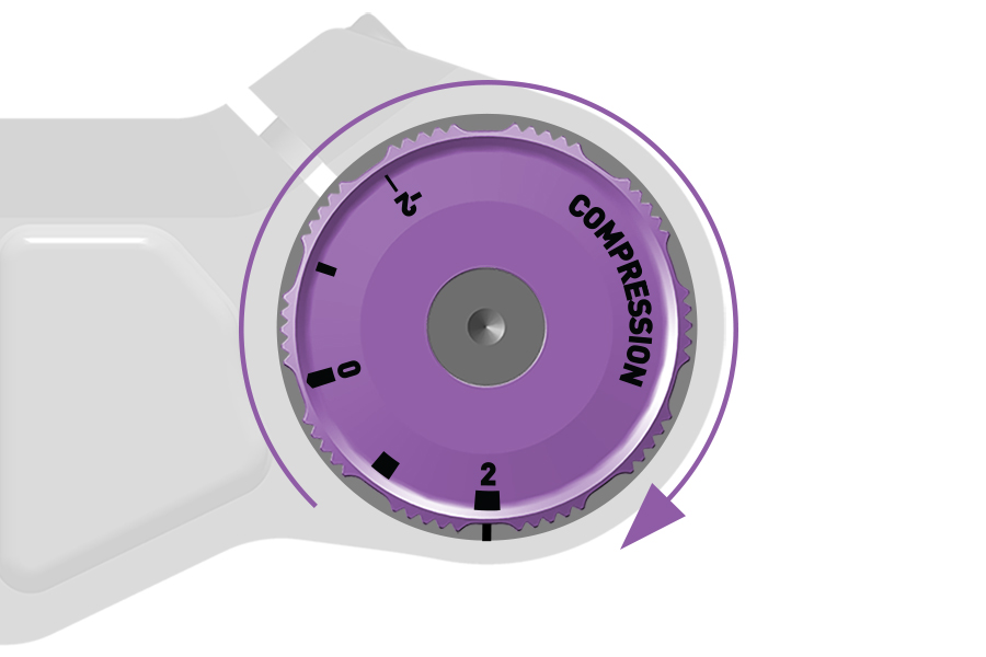
Charger 3 RC, Charger 3.2 RC: Rotate the LSC knob counterclockwise until it stops to adjust to the full open setting.
Rotate the LSC knob clockwise until it stops to adjust to the full closed setting.
Rotate the LSC knob seven clicks, from full clockwise or full counterclockwise, to the middle setting.
Low Speed Compression (LSC) damping adjustment controls compression stroke speed, or the rate at which the fork compresses, during slow compression stroke scenarios. LSC affects bump absorption and efficiency during rider weight shifts, transitions, cornering, more gradual bump impacts, and braking.
Increased LSC damping:
Keeps the suspension fork riding higher in its travel. This may help the rider improve efficiency and maintain momentum over gradual, rolling terrain and through corners.
Suspension compression may feel more firm on bumpier terrain.
Decreased LSC damping:
Allows the fork to compress quickly and easily. This may help the rider maintain momentum and speed on bumpier terrain.
Suspension compression may feel less firm on bumpier terrain.
LSC damping adjustments have less effect during high speed compression stroke scenarios. Drops and large bump impacts can exceed the LSC damper's effective range of control and will cause the suspension fork to compress suddenly and quickly, regardless of the LSC damper setting.
Increase LSC damping to reduce compression stroke speed and increase efficiency on rolling or smoother terrain, and when frequently climbing out of the saddle.
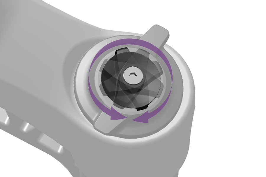
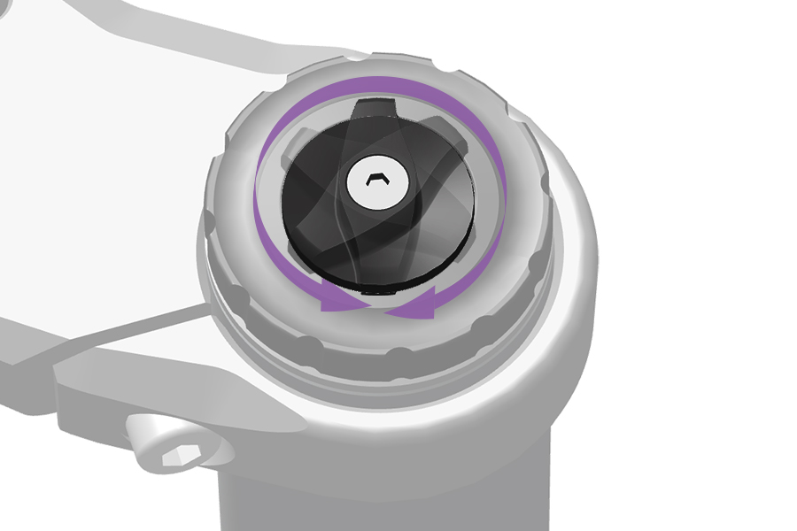
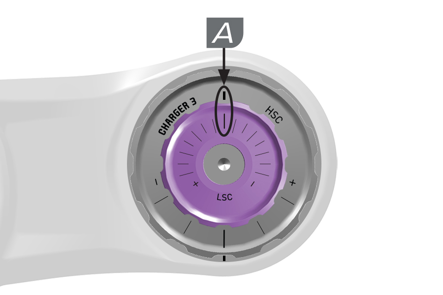
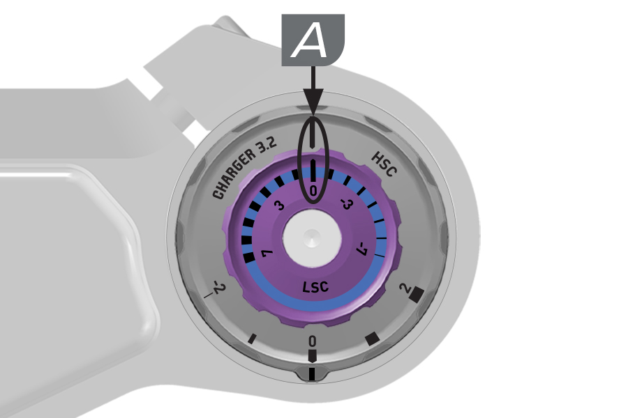
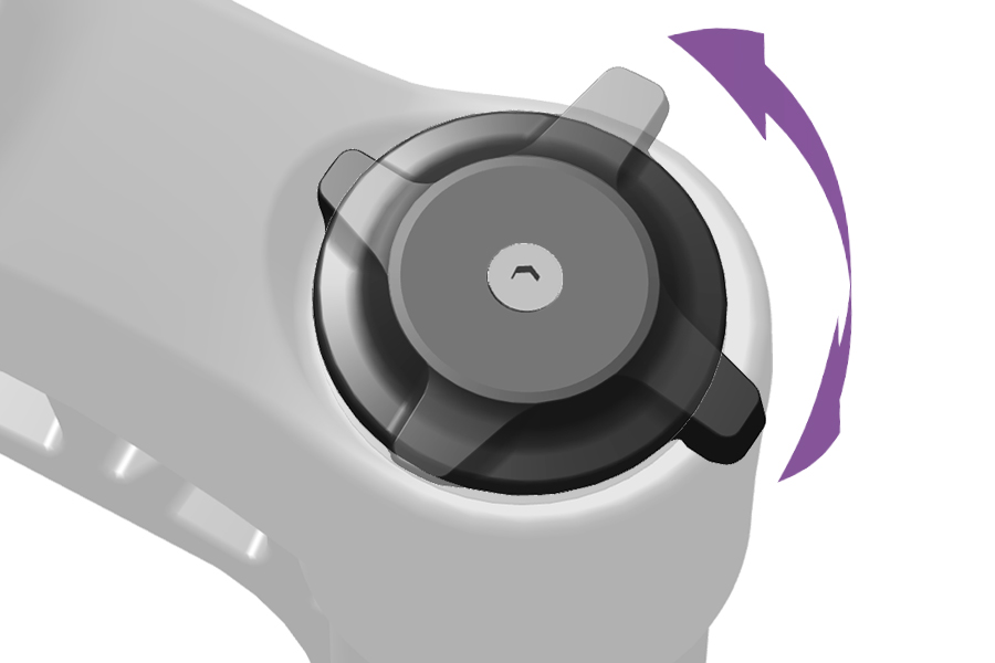
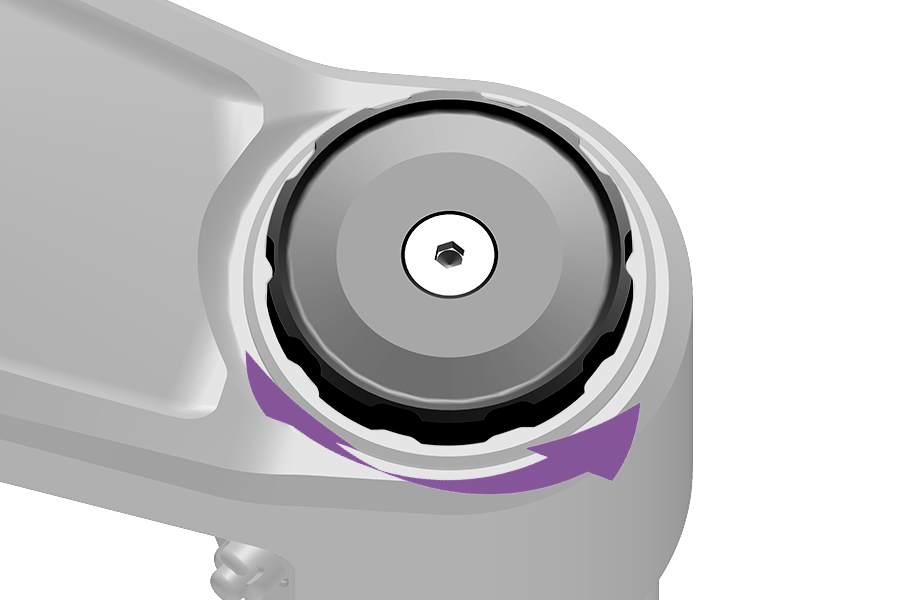
To increase (+) Low Speed Compression damping (firm), turn the compression adjuster knob clockwise.
To decrease (-) Low Speed Compression damping (soft), turn the compression adjuster knob adjuster counterclockwise.
A. DebonAir+ Charger 3 RC2, Charger 3.1 RC2, Charger 3.2 RC2: Start with the middle LSC setting and adjust as preferred.
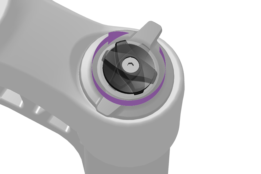
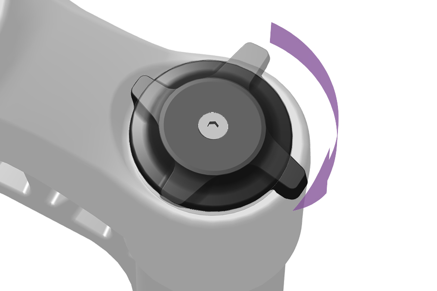
Adjustment:
To improve efficiency on rolling and smoother terrain, rotate the LSC or compression adjuster knob clockwise to increase compression damping and firmness, and decrease compression stroke speed.
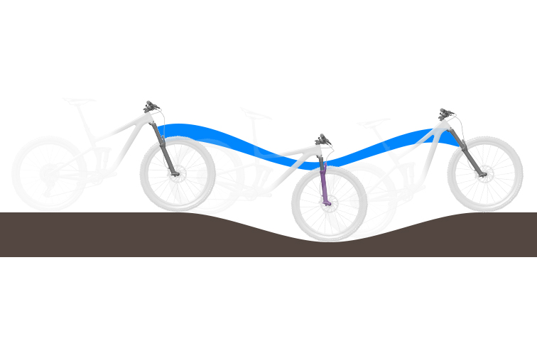
Low Speed Compression Damping - Open / Too Soft
The fork compresses at the low point of the terrain. Suspension travel is used quickly, the rider's weight may shift forward, and bicycle momentum may be reduced.
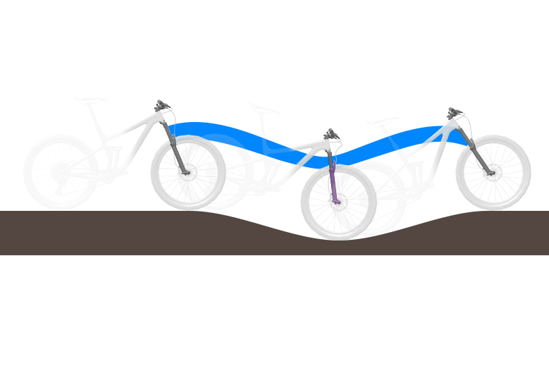
Low Speed Compression Damping - Mid to Firm
The fork resists compressing, remains higher in its travel, and helps the rider maintain speed into and through the rolling section of terrain.
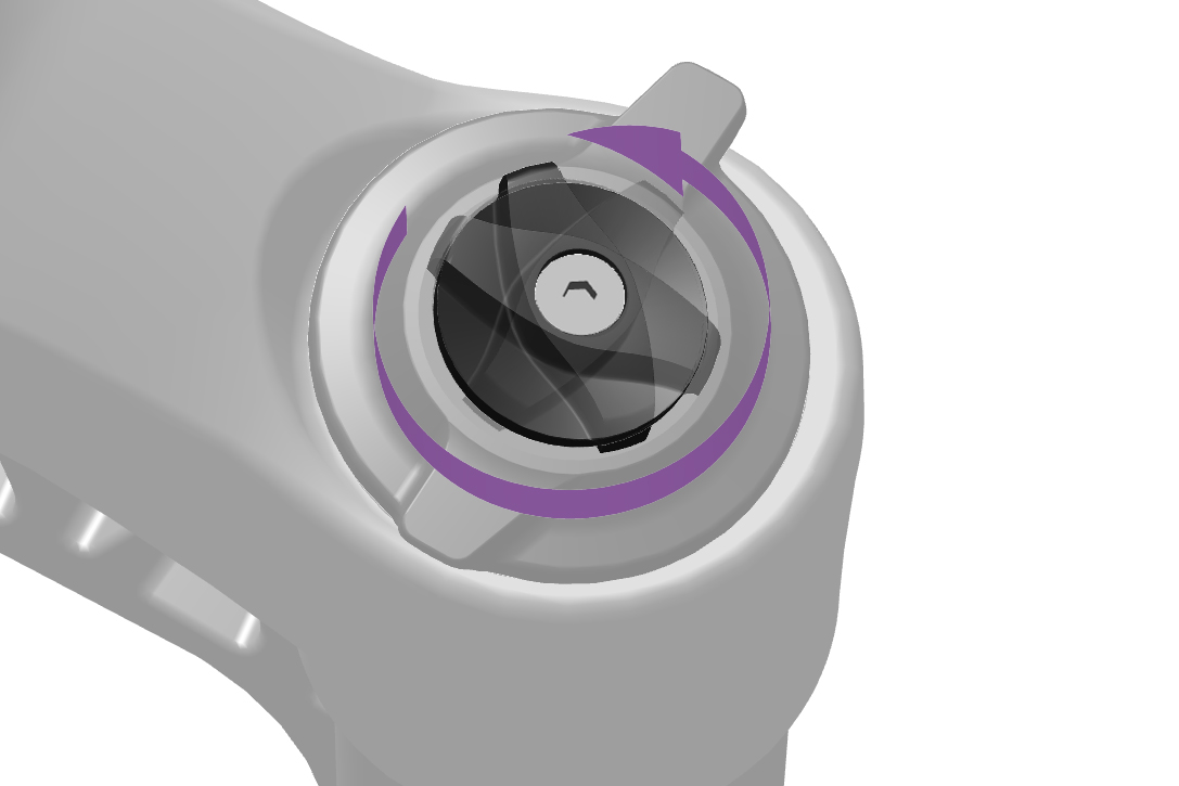
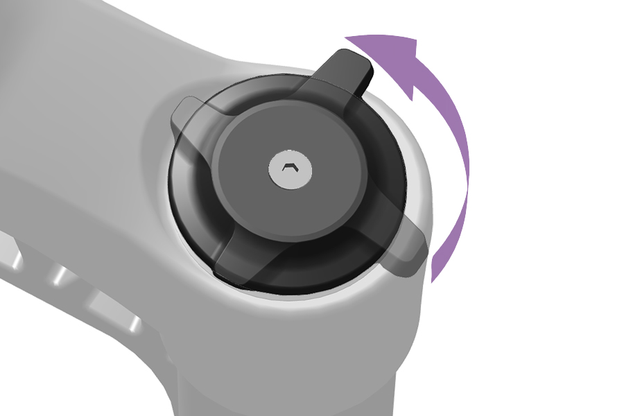
Adjustment:
To increase small bump sensitivity, rotate the LSC or compression adjuster knob counterclockwise to decrease compression damping and firmness, and increase compression stroke speed.
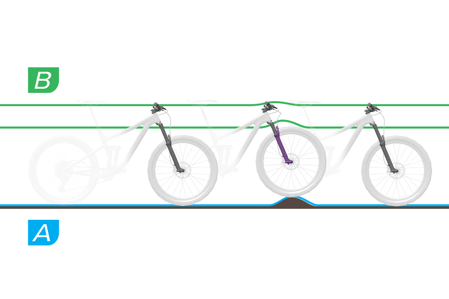
Low Speed Compression Damping - Soft to Mid
A. At bump impact, the fork compresses quickly and freely, and the bump is absorbed. Traction is maintained.
B. The fork reacts quickly to the impact. The crown and handlebar rise slightly as the bump is absorbed.
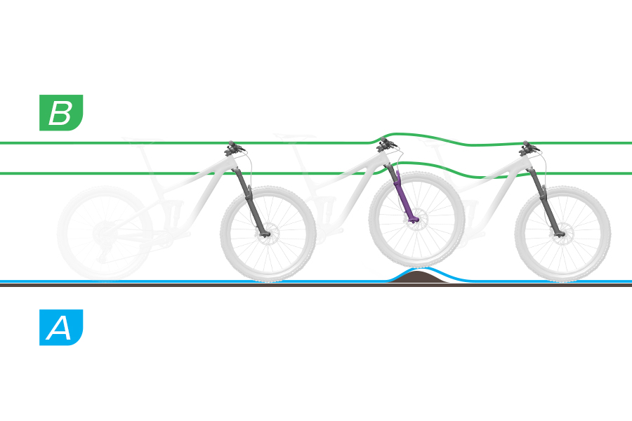
Low Speed Compression Damping - Too Firm
A. At bump impact, the fork compresses too slowly and the wheel deflects off of the bump. Traction is decreased as the wheel leaves the ground.
B. The crown and handlebar are forced upward significantly, which can decrease control.
Low Speed Compression (LSC) damping controls shock compression speed during slow compression stroke scenarios, such as rider weight transfer, small impacts, and cornering, which improves control and efficiency.
Too much compression damping makes the suspension feel too firm over bumps.
To increase or decrease compression damping, rotate the knob or lever in the direction or position indicated on the shock.
Flight Attendant: Refer to the Flight Attendant User Manual for Low Speed Compression (LSC) details and procedures.
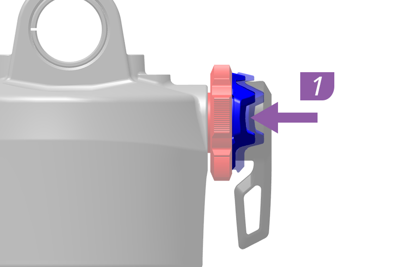
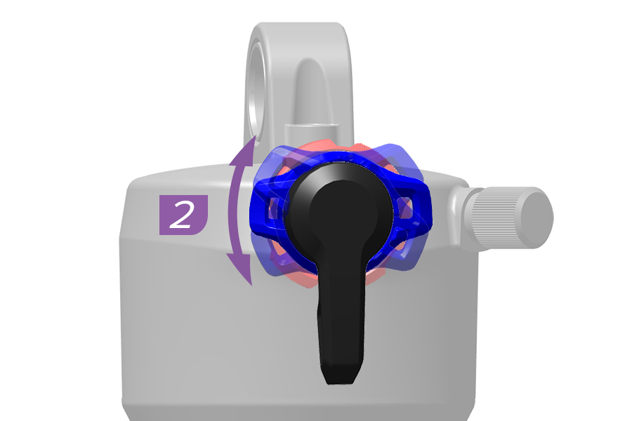
1. Push the blue compression adjuster inward.
2. Rotate the blue compression adjuster clockwise to increase Low Speed Compression damping. Rotate the blue compression adjuster counterclockwise to decrease Low Speed Compression damping.
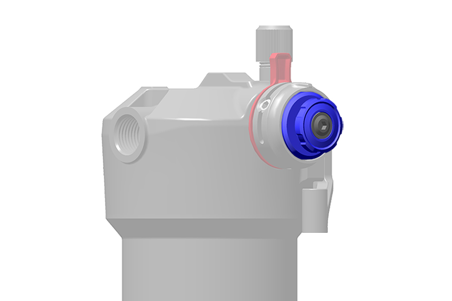
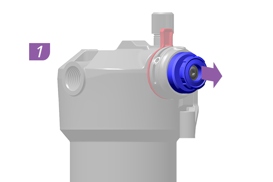
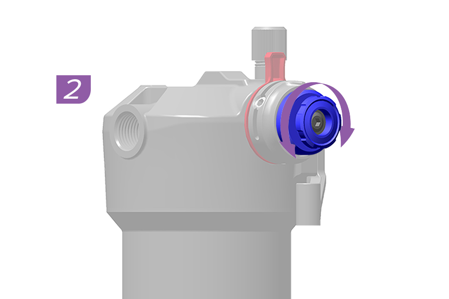
1. Pull the blue compression adjuster outward.
2. Rotate the blue compression adjuster clockwise to increase Low Speed Compression damping. Rotate the blue compression adjuster counterclockwise to decrease Low Speed Compression damping.
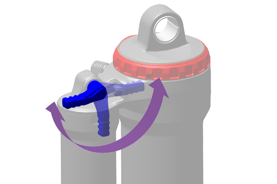
Refer to the decals on the shock for lever position and function.
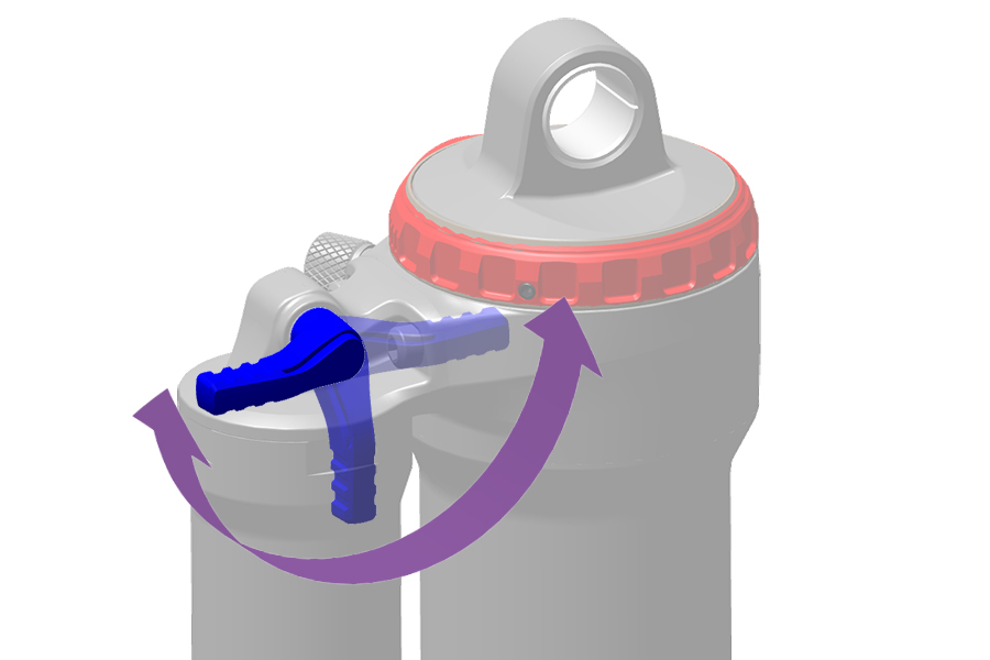
Refer to the decals on the shock for lever position and function.
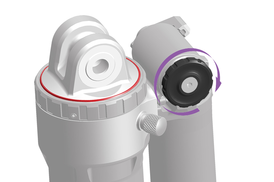
Refer to the decals on the shock for lever position and function.
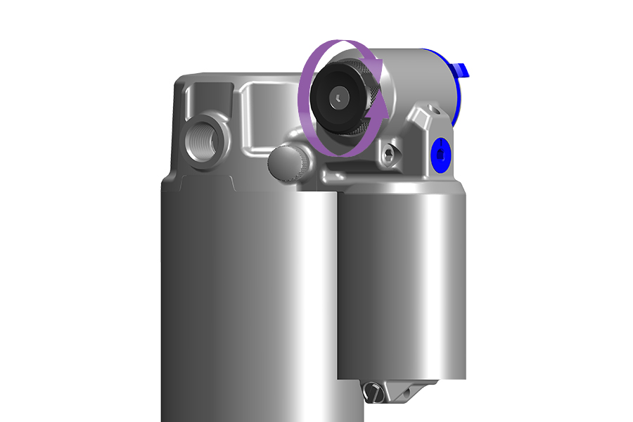
Refer to the graphics on the shock for adjuster position and function.
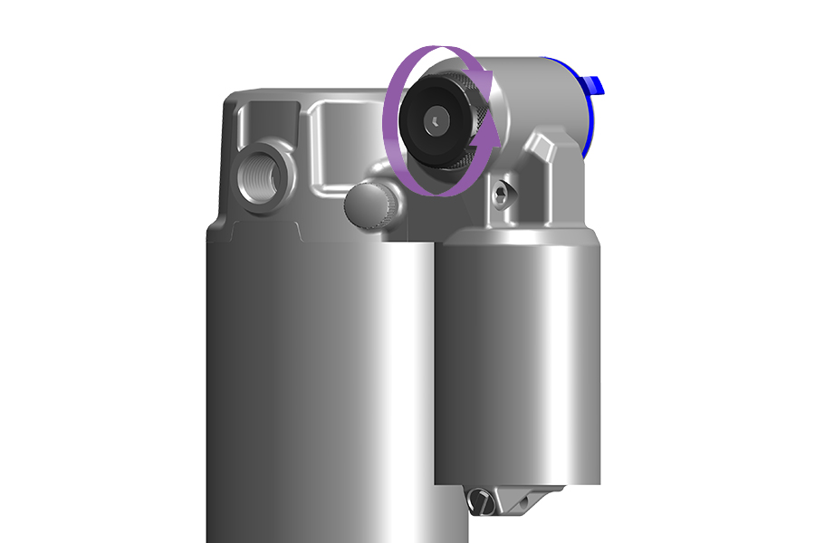
Refer to the graphics on the shock for adjuster position and function.
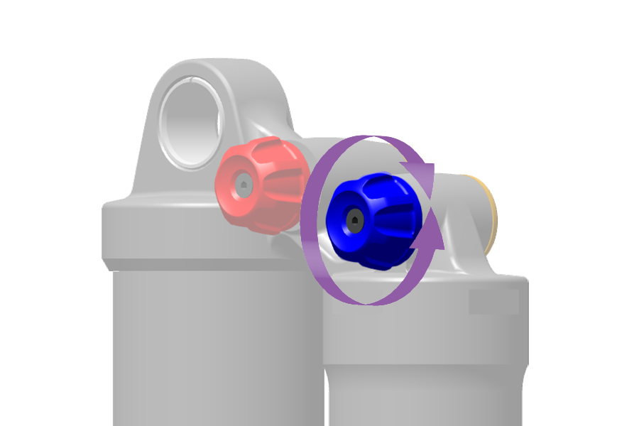
Refer to the decals on the shock for lever position and function.
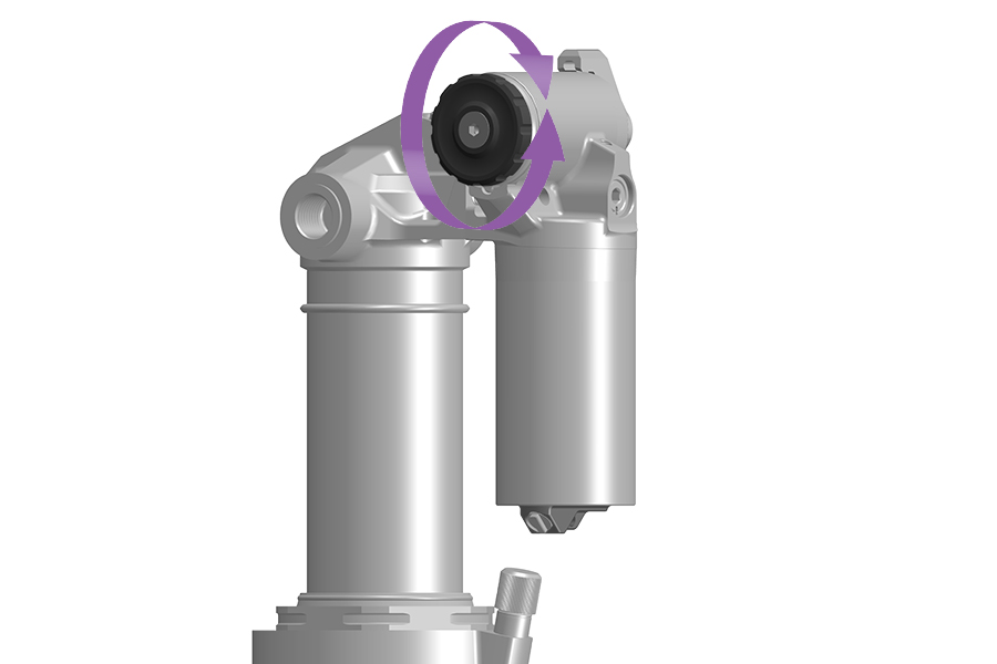
Refer to the decals on the shock for lever position and function.
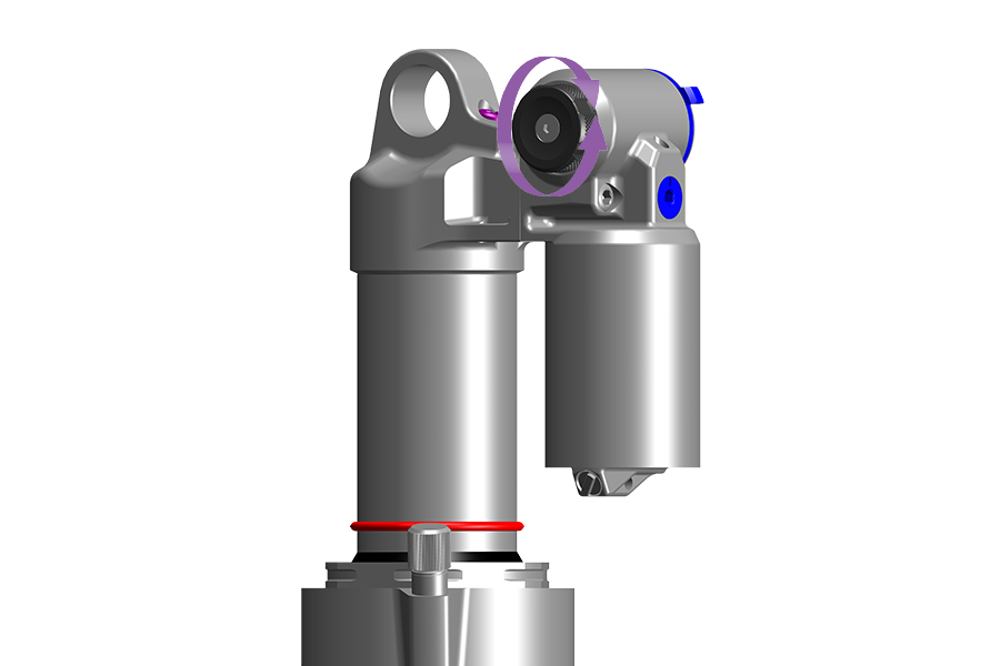
Refer to the graphics on the shock for adjuster position and function.
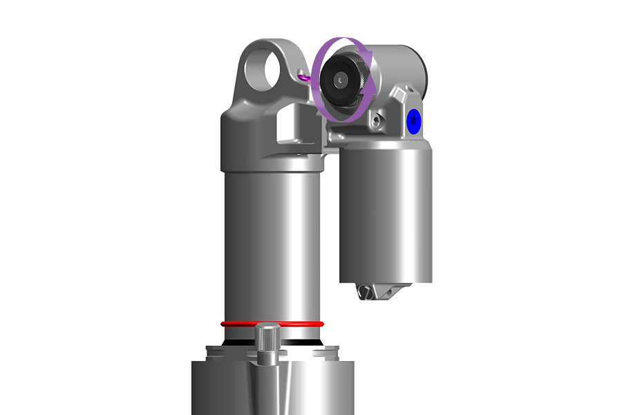
Refer to the graphics on the shock for adjuster position and function.
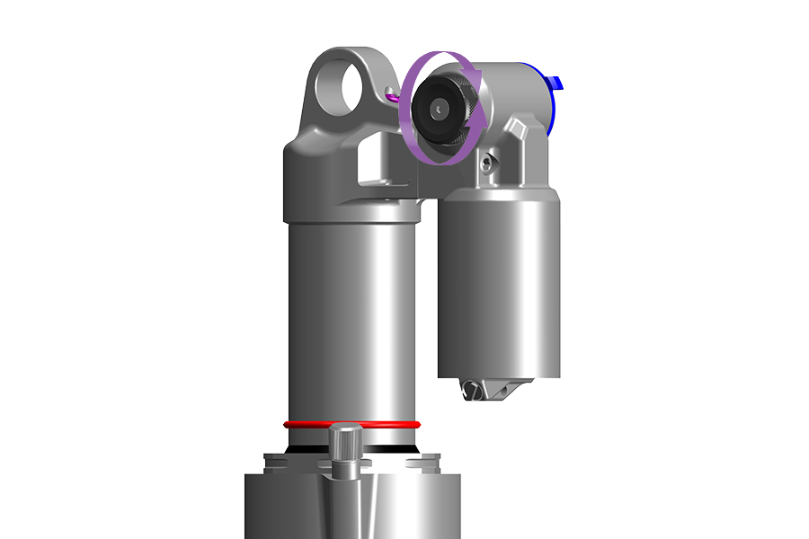
Refer to the graphics on the shock for adjuster position and function.
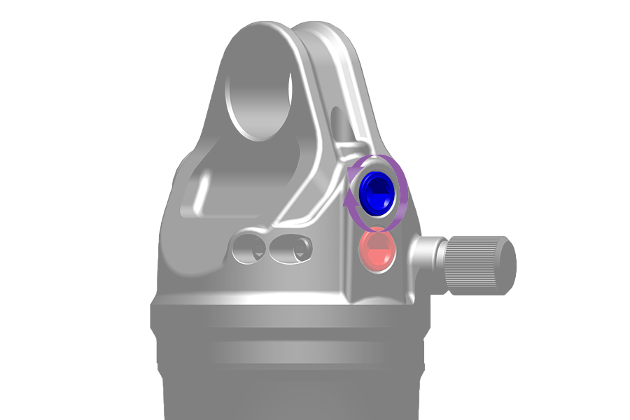
Refer to the decals on the shock for lever position and function.
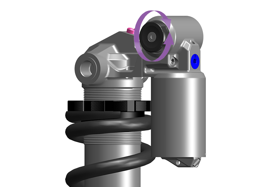
Refer to the graphics on the shock for adjuster position and function.
.jpg)
Refer to the graphics on the shock for adjuster position and function.
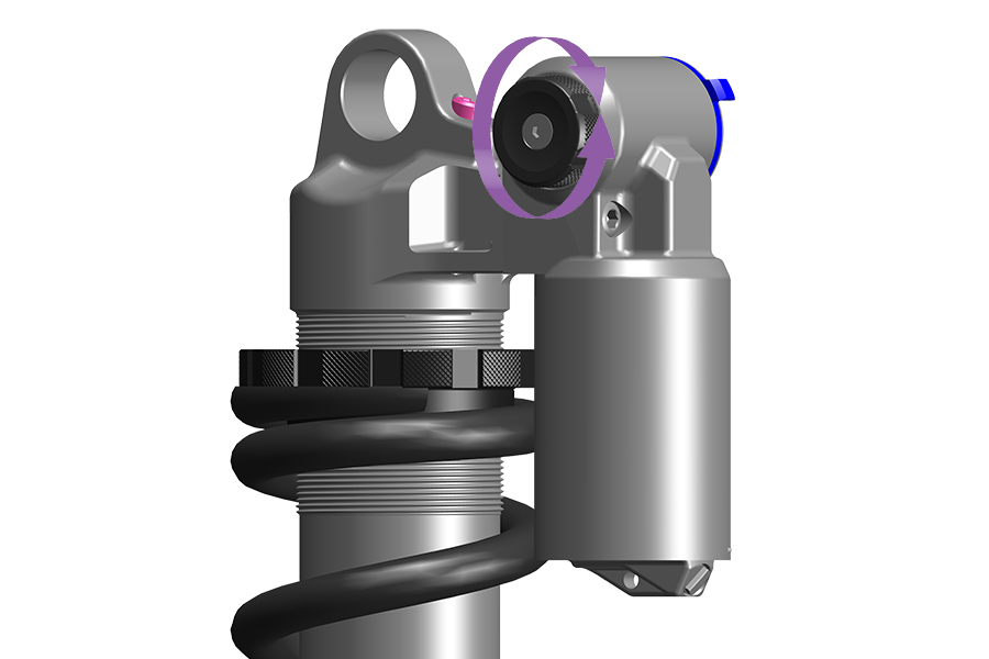
Refer to the graphics on the shock for adjuster position and function.
Low speed compression (LSC) damping adjustment controls compression stroke speed, or the rate at which the shock compresses, during slow compression stroke scenarios. LSC affects bump absorption and efficiency during rider weight shifts, transitions, cornering, more gradual bump impacts, and braking.
Increased LSC damping:
Keeps the shock riding higher in its travel. This may help the rider improve efficiency and maintain momentum over gradual, rolling terrain, through corners and while pedaling.
Suspension compression may feel more firm on bumpier terrain.
Decreased LSC damping:
Allows the shock to compress quickly and easily. This may help the rider maintain momentum and speed on bumpier terrain.
Suspension compression may feel less firm on bumpier terrain.
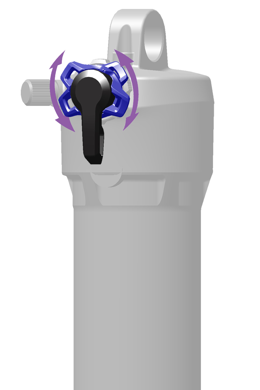
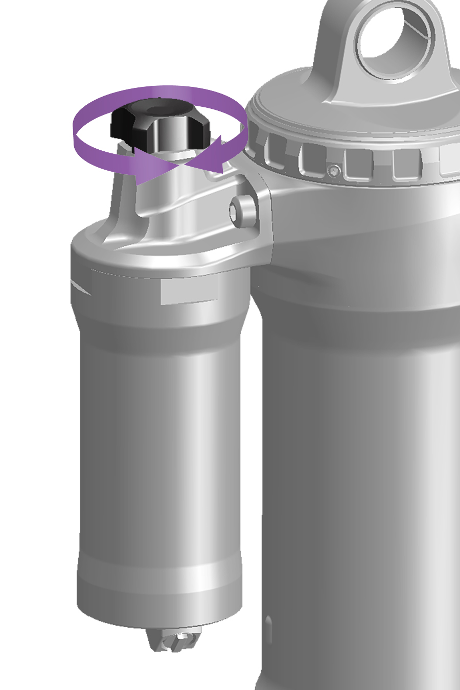
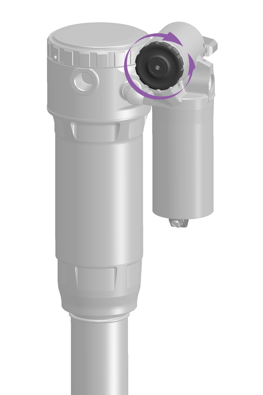
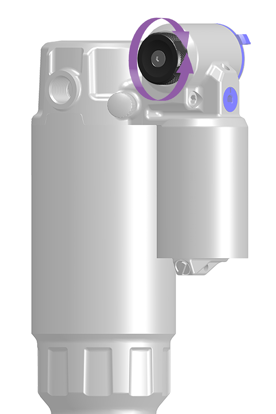
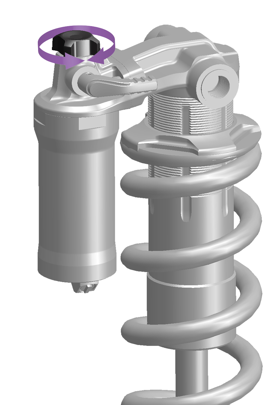
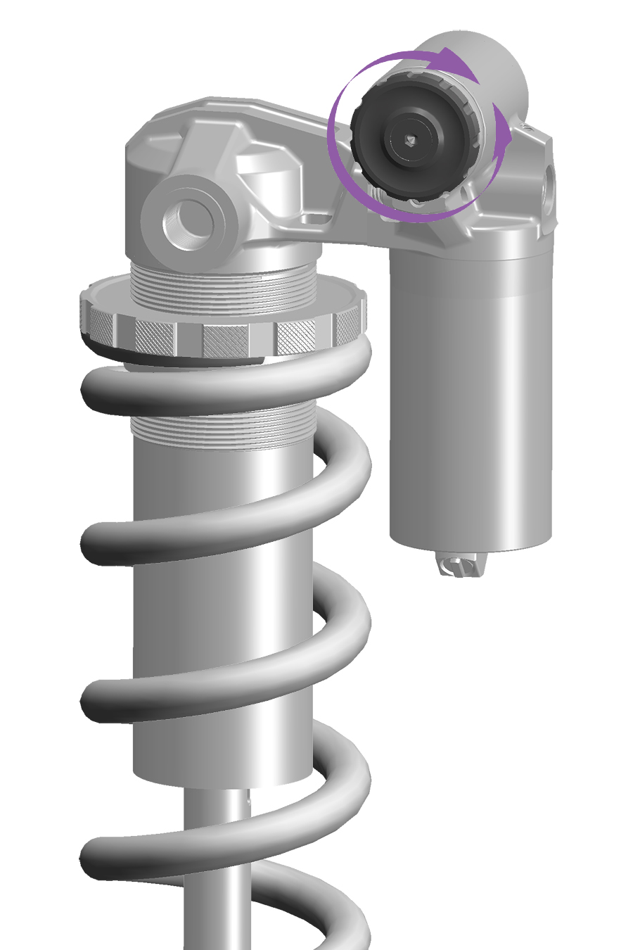
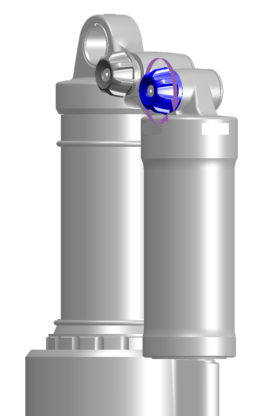
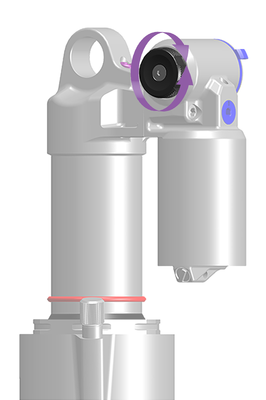
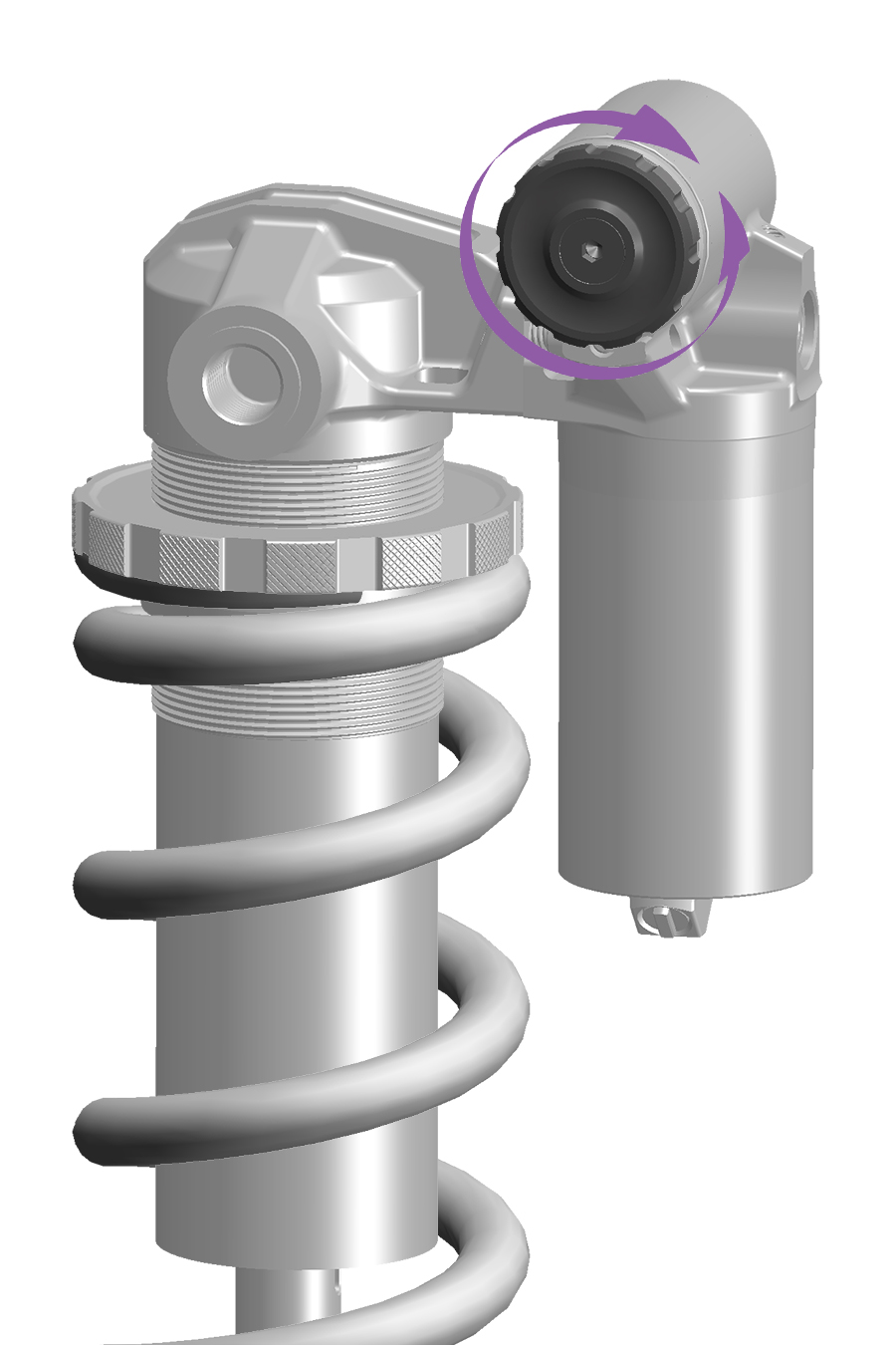
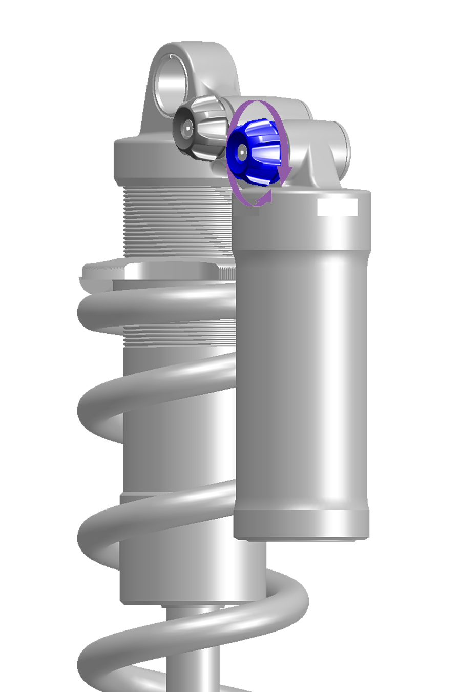
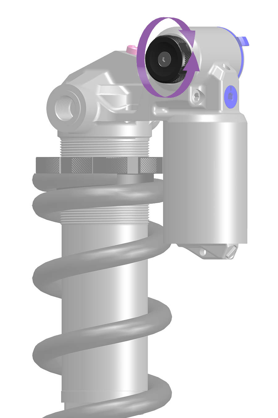
To increase (+) Low Speed Compression damping (firm), turn the compression adjuster clockwise.
To decrease (-) Low Speed Compression damping (soft), turn the compression adjuster counterclockwise.
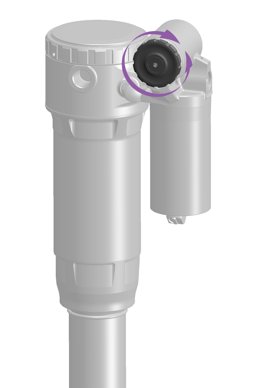
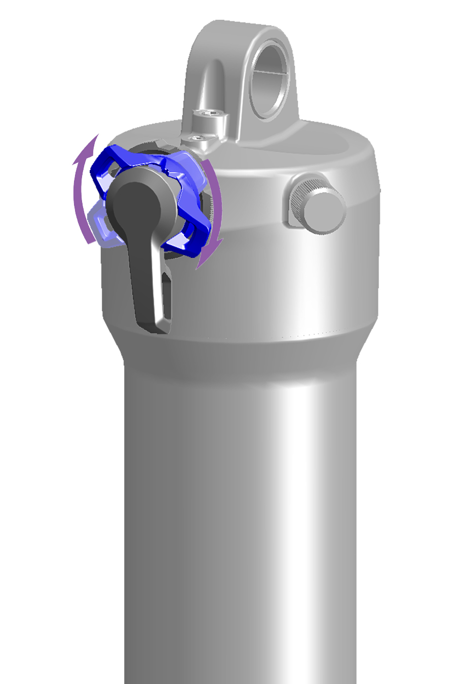
Adjustment: To improve efficiency on rolling and smoother terrain, rotate the compression adjuster clockwise to increase compression damping and firmness, and decrease compression stroke speed.
Low Speed Compression Damping - Open / Too Soft
The shock compresses low into the compression stroke through the low point of the terrain. Suspension travel is used quickly, the rider's weight may shift downward, and bicycle momentum may be reduced.
Low Speed Compression Damping - Mid to Firm
The shock resists compressing, remains higher in its travel, and helps the rider maintain speed into and through the rolling section of terrain.
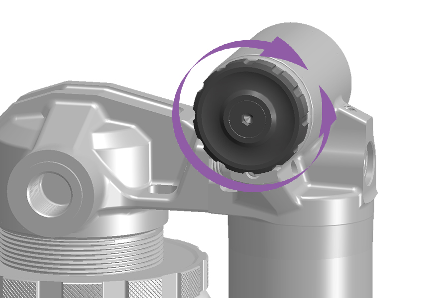
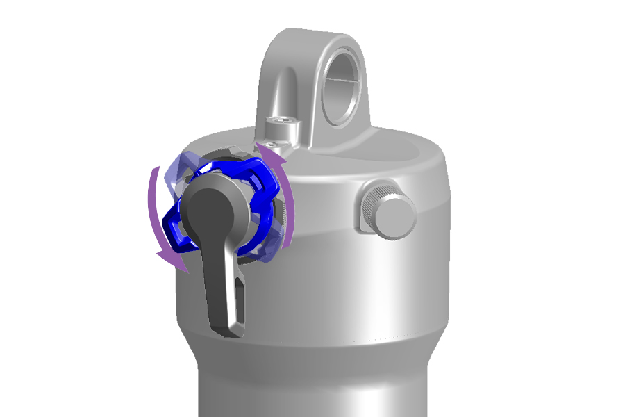
Adjustment: To increase small bump sensitivity, rotate the LSC or compression adjuster counterclockwise to decrease compression damping and firmness, and increase compression stroke speed.
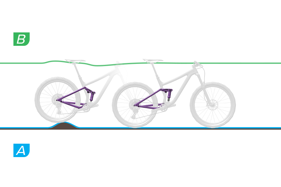
Low Speed Compression Damping - Soft to Mid
A. At bump impact, the shock compresses quickly and freely, and the bump is absorbed. Traction is maintained.
B. The saddle rises slightly as the bump is absorbed.
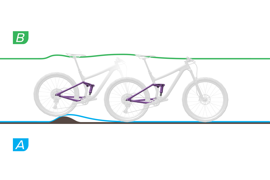
Low Speed Compression Damping - Too Firm
A. At bump impact, the shock compresses too slowly and the rear wheel deflects off of the bump. Traction is decreased.
B. The saddle and rider are forced upward and forward, the rear wheel loses contact with the ground, and control is decreased.
The Threshold (T), or Pedal, position prevents the suspension fork from compressing until moderate bump impact or downward force occurs. Threshold position increases efficiency on smoother terrain.
Use the Threshold (T) setting to increase pedaling efficiency on flat, rolling, smooth, or moderately bumpy terrain. When in the Threshold setting, increased bicycle speed will increase bump impact force causing the fork to compress and absorb the bump.
When the adjuster knob is in the (A) Open position (full counterclockwise) the suspension fork will compress quickly and freely through its full range of travel when bump impact or downward force occurs.
When the adjuster knob is in the (B) Threshold position the suspension fork will resist compressing until moderate bump impact or downward force occurs.
When the adjuster knob is in the (C) Lock position (full clockwise) position the suspension fork will resist compressing into its travel until significant bump impact or downward force occurs.
To activate Threshold, rotate the knob to the Threshold position.
Threshold (Pedal) on forks equipped with a remote can be actuated with the handlebar mounted remote at any time during use. Refer to the appropriate remote user manual at sram.com/service for more information.
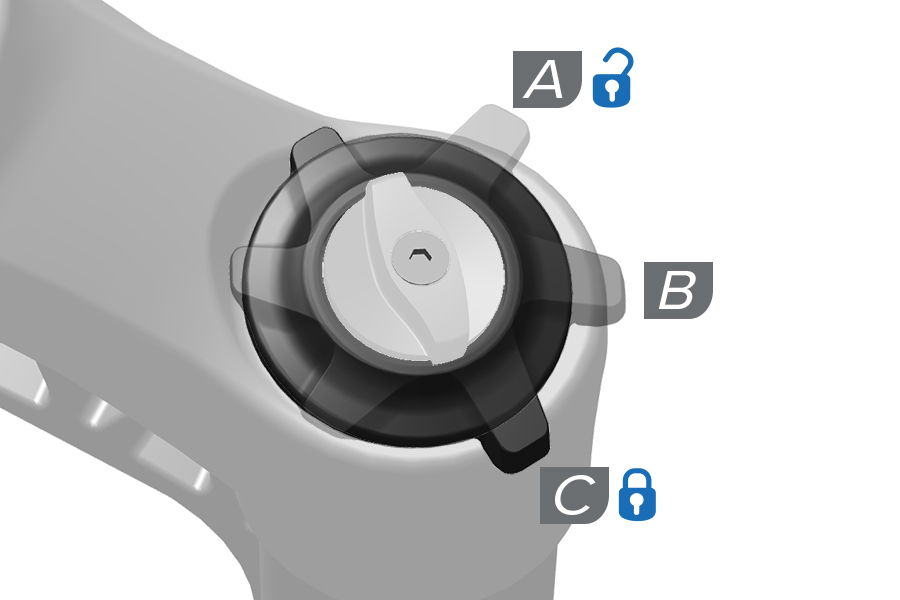
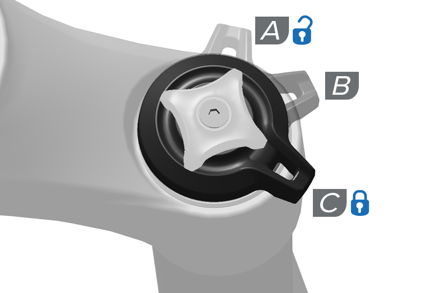
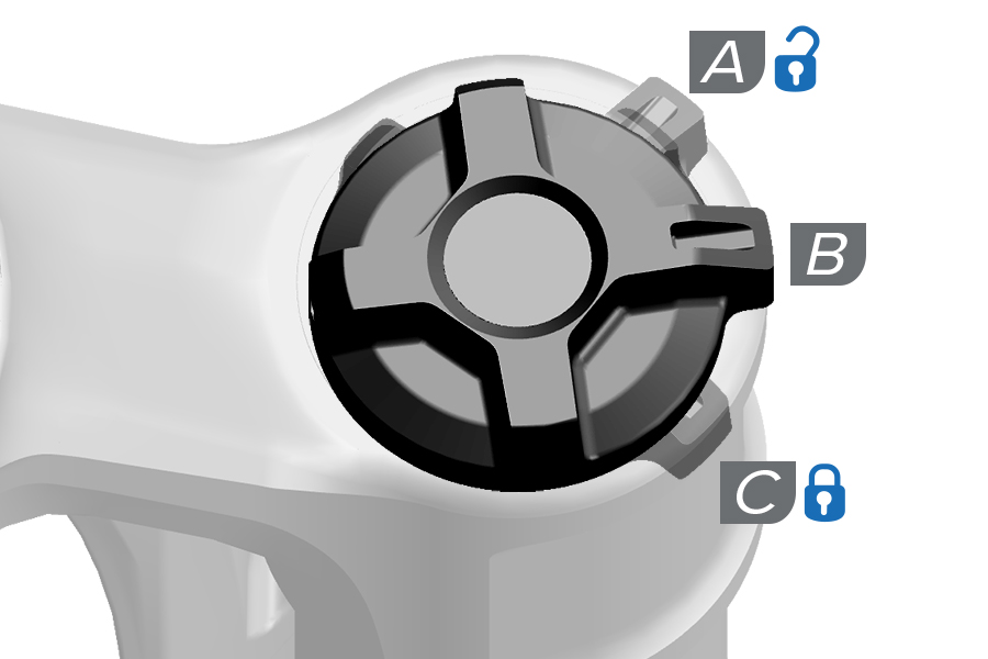
Threshold (T), or Pedal, mode prevents the rear shock from compressing until moderate to significant bump impact or downward force occurs. Threshold mode increases efficiency on smoother terrain.
Use the Threshold setting to increase pedaling efficiency on flat, rolling, smooth, or moderately bumpy terrain. When in Threshold mode, increased bicycle speed will increase bump impact force causing the shock to compress and absorb the bump.
When the adjuster is in the (A) Open position the shock will compress quickly and freely through its full range of travel.
When the adjuster is in the (B) Threshold position the shock will resist compressing until moderate bump impact or downward force occurs.
When the adjuster is in the (C) Lock position the shock will resist compressing into its travel until significant bump impact or downward force occurs.
To activate Threshold, rotate the adjuster lever to the Threshold position.
Threshold on remote-equipped shocks can be actuated with the handlebar mounted remote at any time during use. Refer to the appropriate remote user manual at www.sram.com/en/rockshox/products/remotes for more information.
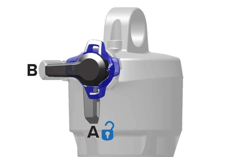
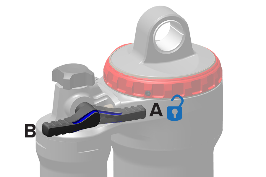
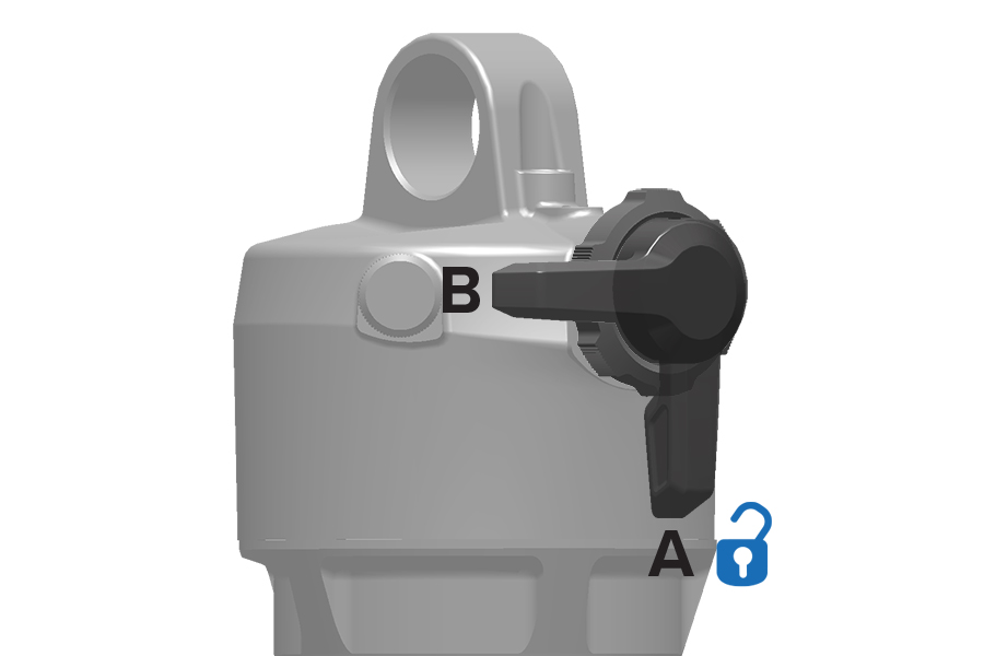
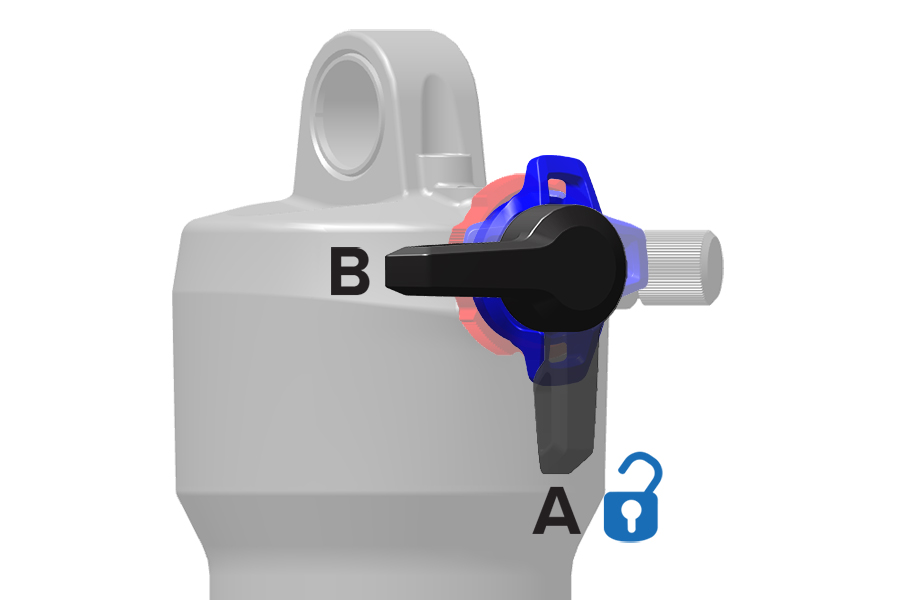
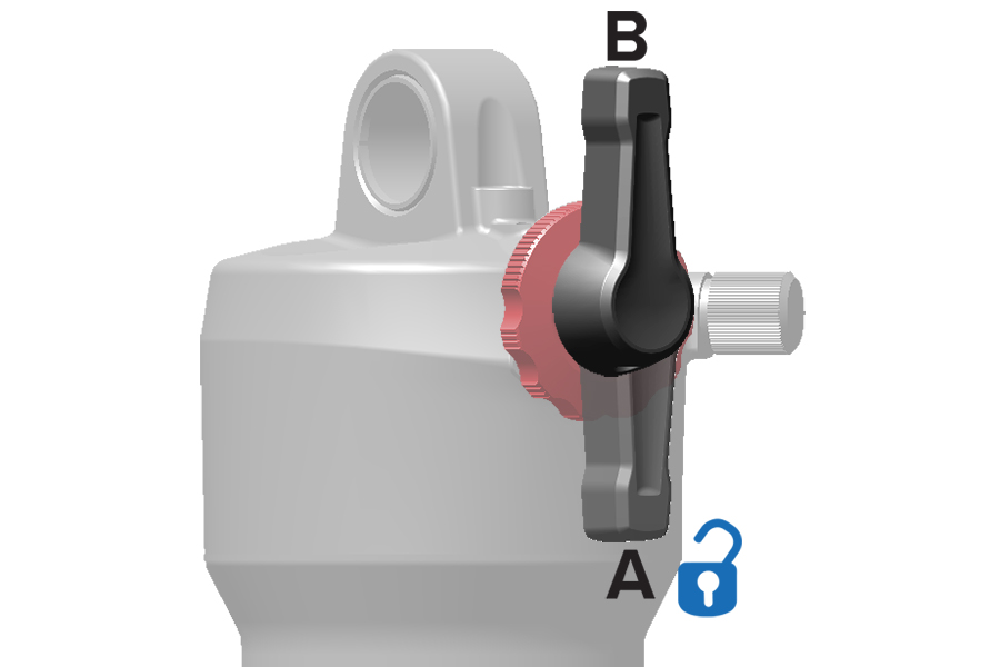
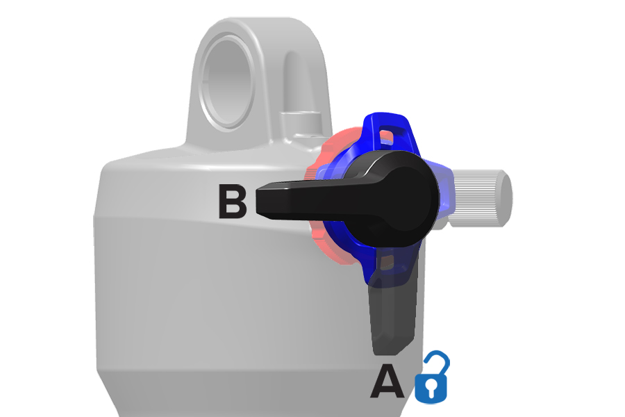
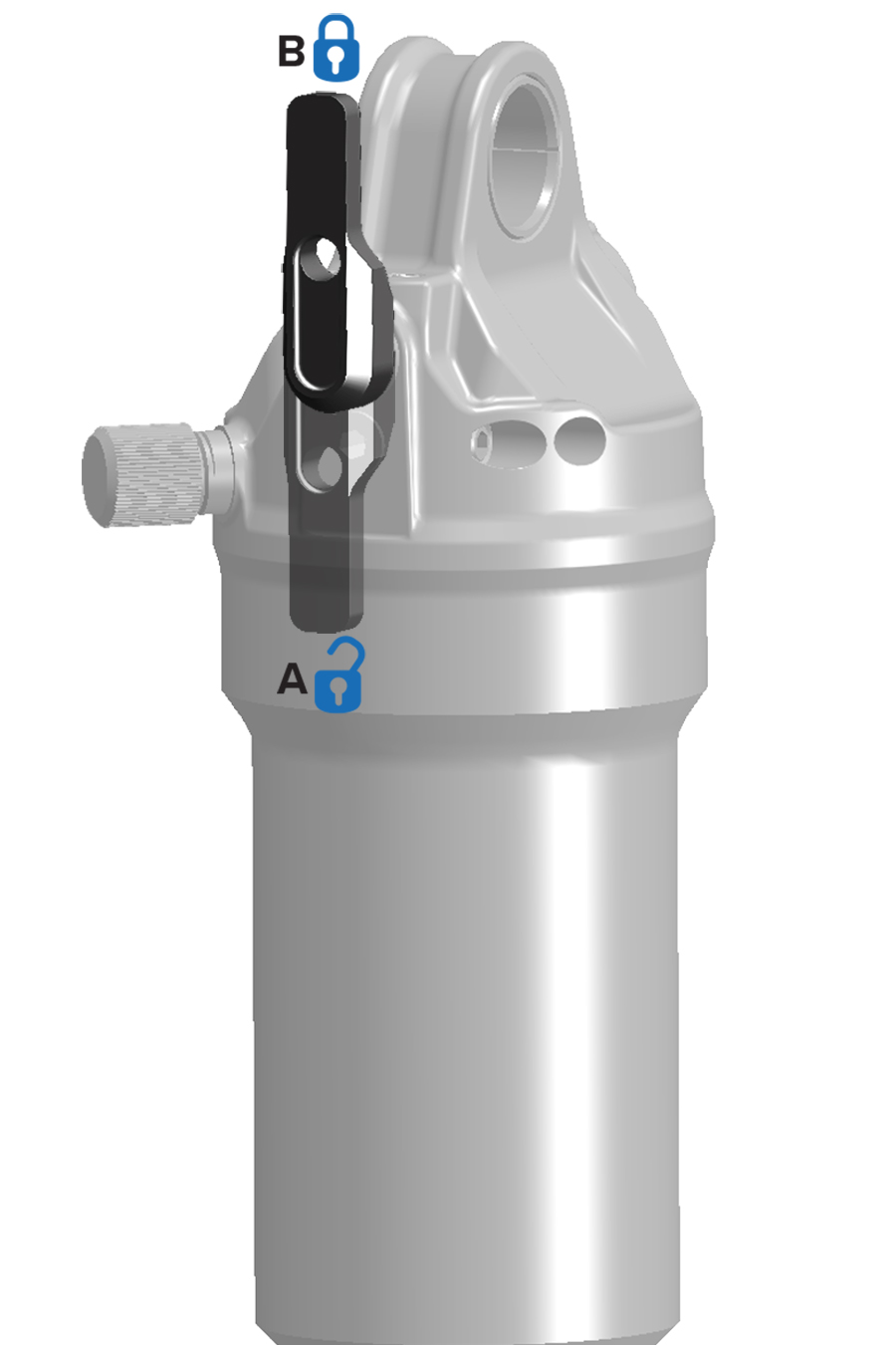
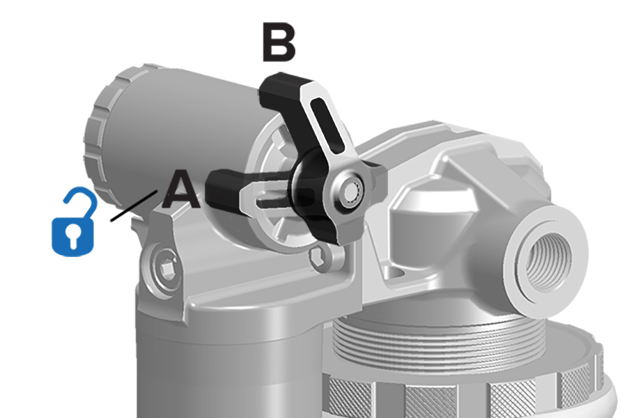
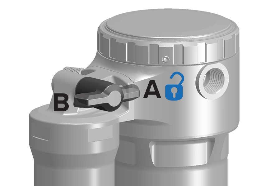
.jpg)
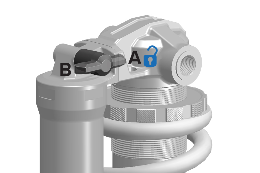
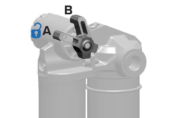
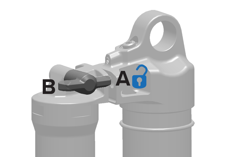
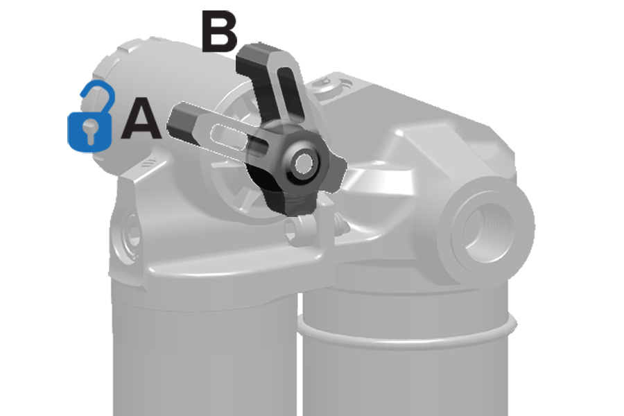
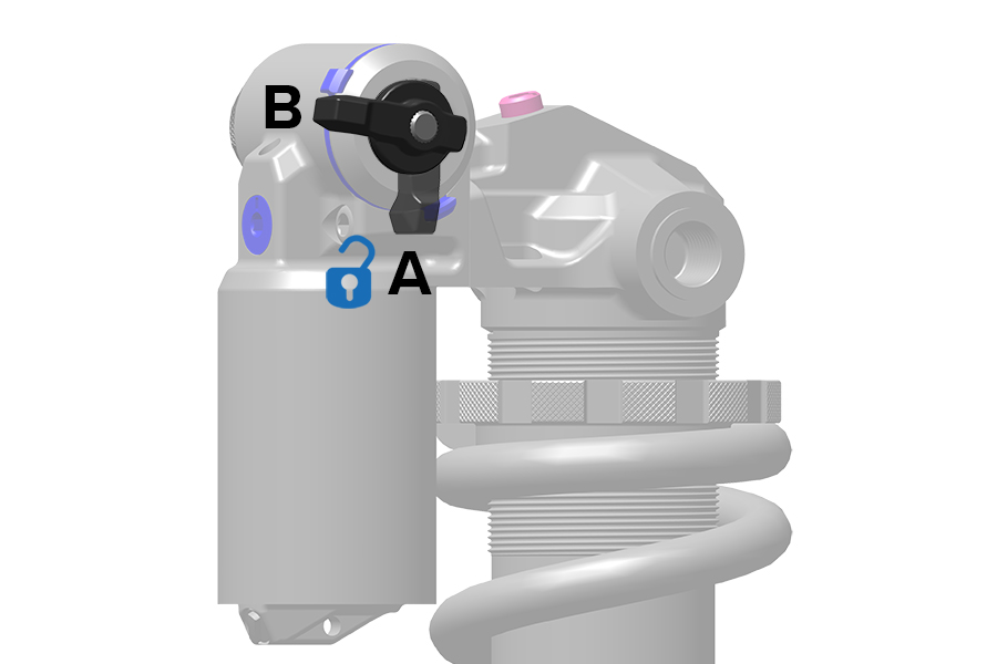
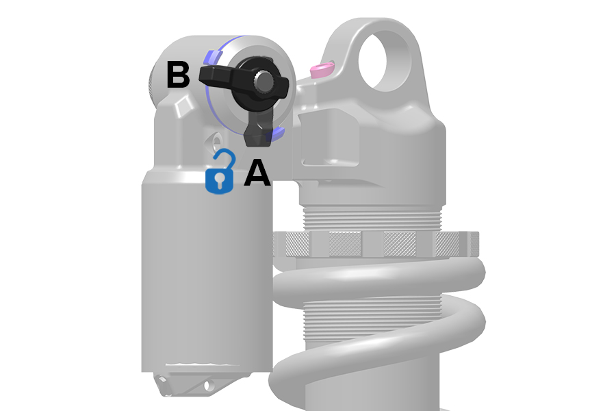
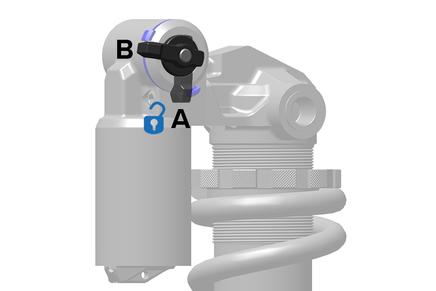
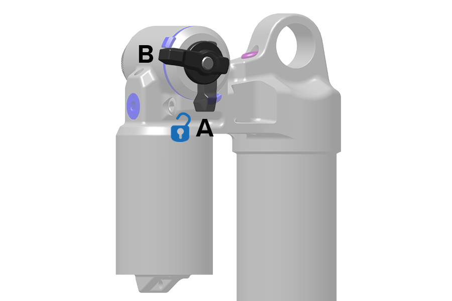
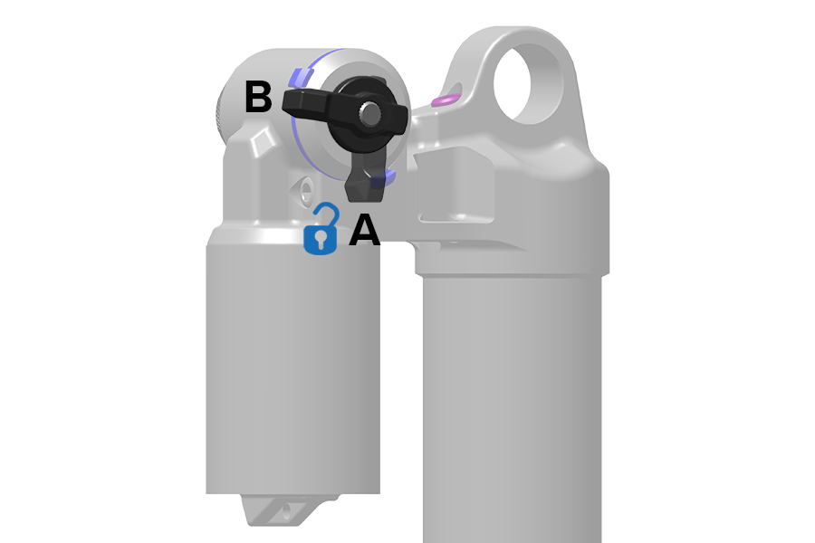
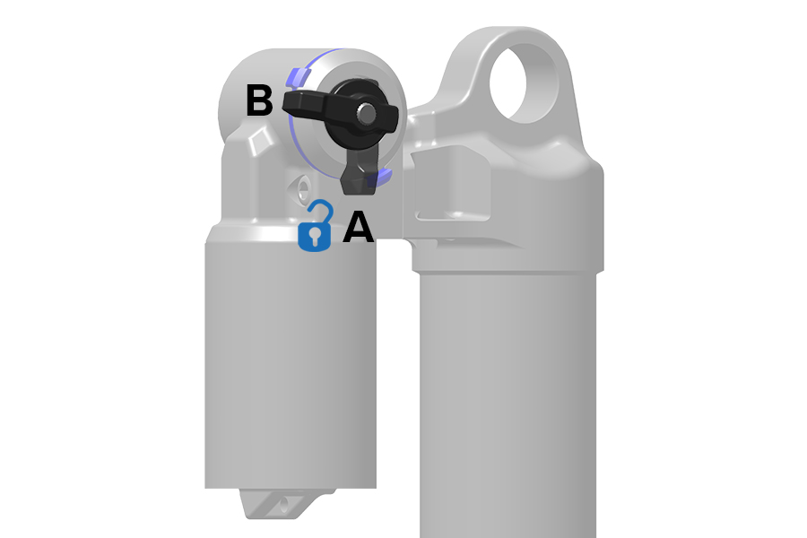
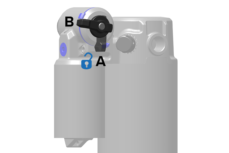
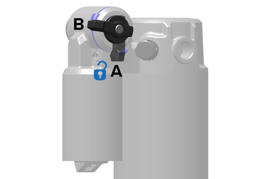
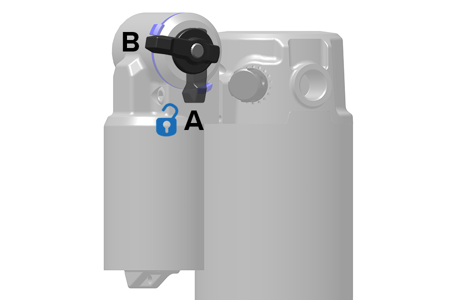
Lock position features key rider benefits when activated - Compliance and Blow-Off.
Motion Control and Turnkey:
(A) Compliance - A fixed amount of suspension fork movement that improves traction and control over small bumps while in the Lock position.
When in Lock position, a small amount of compliance prevents the wheel from bouncing off of impacts which helps maintain traction.
Charger Race Day, Charger Race Day 2, Charger Race Day 2 Flight Attendant, Charger, Charger 2, Charger 2.1, Rush, Motion Control, and Turnkey:
(B) Blow-Off - A valve in the compression damper that allows the suspension fork to safely compress if an impact greater than the valve's Lock force is encountered, such as a drop or large bump.
The Blow-Off valve allows the suspension fork to compress without causing internal damage to the damper.
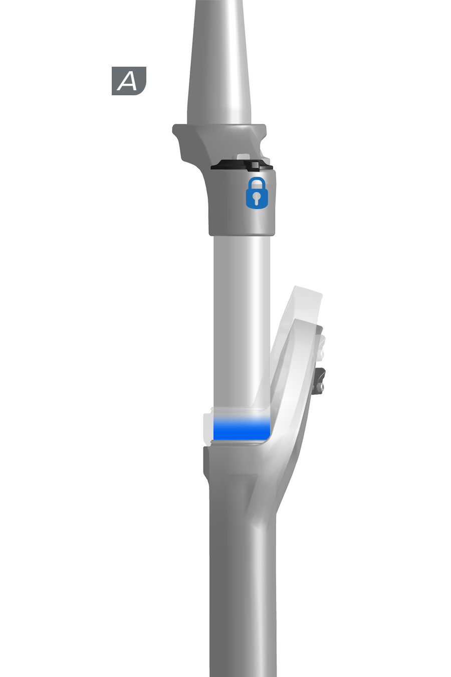
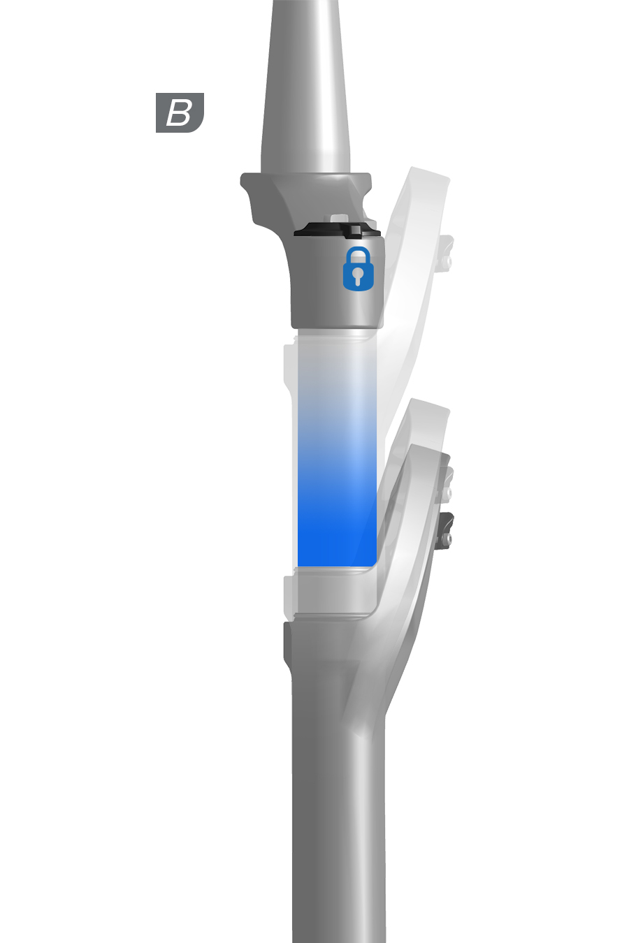
Lock (L) position prevents the suspension fork from compressing. Use Lock position for maximum pedaling efficiency on smoother terrain.
When the adjuster is in the (A) Open position (full counterclockwise), the suspension fork is able to compress quickly and freely through its full range of travel.
To deactivate Lock position, rotate the adjuster counterclockwise.
When the adjuster is in the (B or C) Lock position (full clockwise), the suspension fork will resist compressing into its travel until significant bump impact or downward force occurs.
To activate Lock position, rotate the adjuster clockwise until it stops.
Lock position on forks equipped with a remote can be actuated with the handlebar mounted remote at any time during use. Refer to the appropriate remote user manual at sram.com/service for more information.
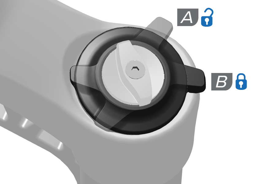
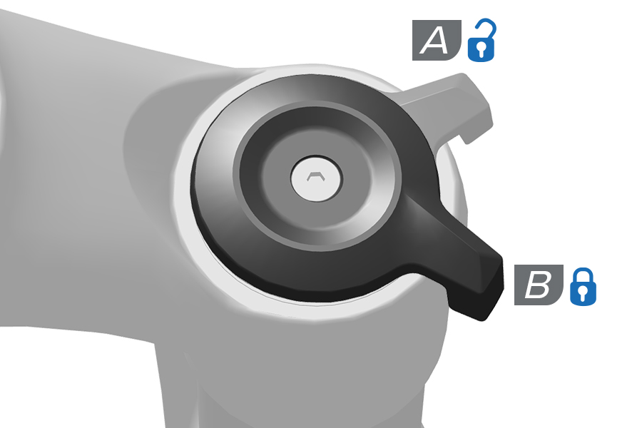
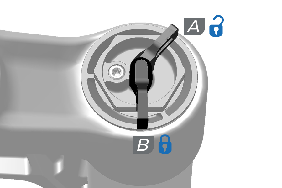
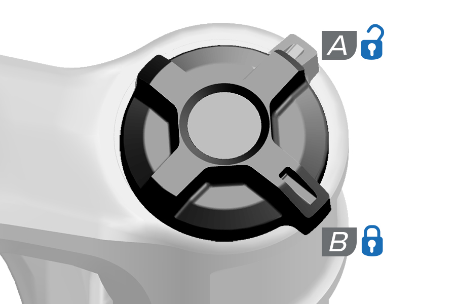
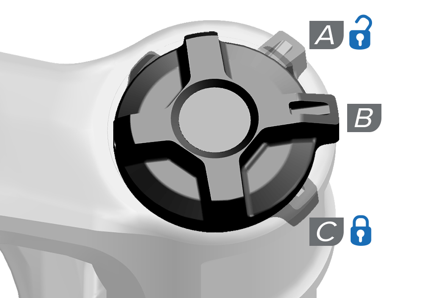
Lock (L) position prevents the rear shock from compressing. Use Lock for maximum pedaling efficiency on smoother terrain.
When the Lock adjuster lever is in the (A) Open position the shock is able to compress quickly and freely through its full range of travel.
To deactivate Lock, rotate the adjuster lever to the Open position.
When the Lock adjuster lever is in the (B) Lock position the shock will resist compressing into its travel until significant bump impact or downward force occurs.
To activate Lock, rotate the adjuster lever to the Lock position.
Lock on remote-equipped shocks can be actuated with the handlebar mounted remote at any time during use. Refer to the appropriate remote user manual at www.sram.com/en/rockshox/products/remotes for more information.
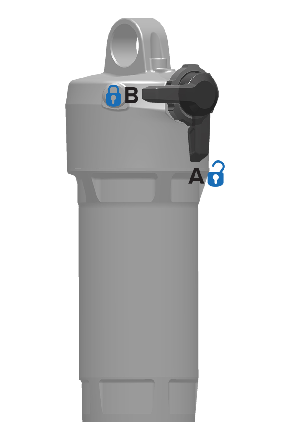
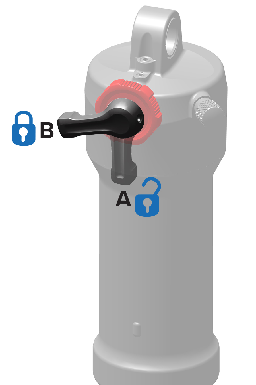
.jpg)
Threshold (T) / Pedal and/or Lock position can be actuated any time during use with the included cable or hydraulic remote on some RockShox front suspension forks.
Consult the appropriate RockShox remote user manual at sram.com/service for installation and operation instructions.
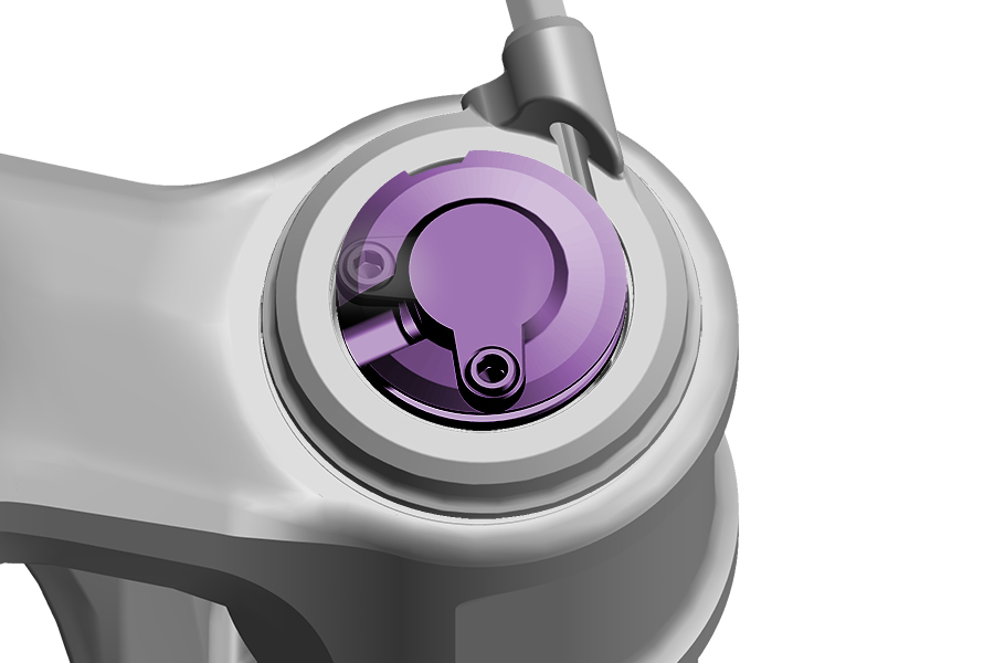
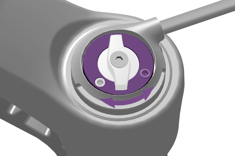
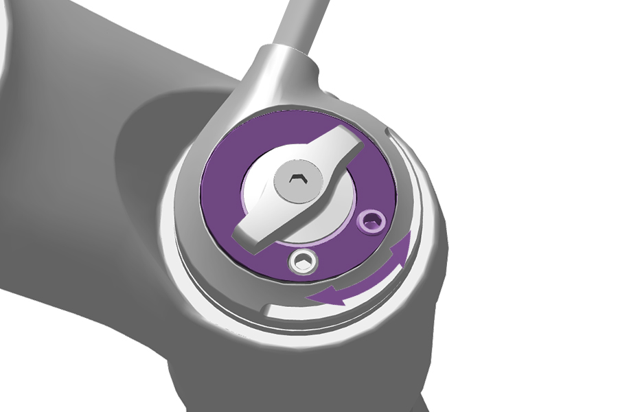
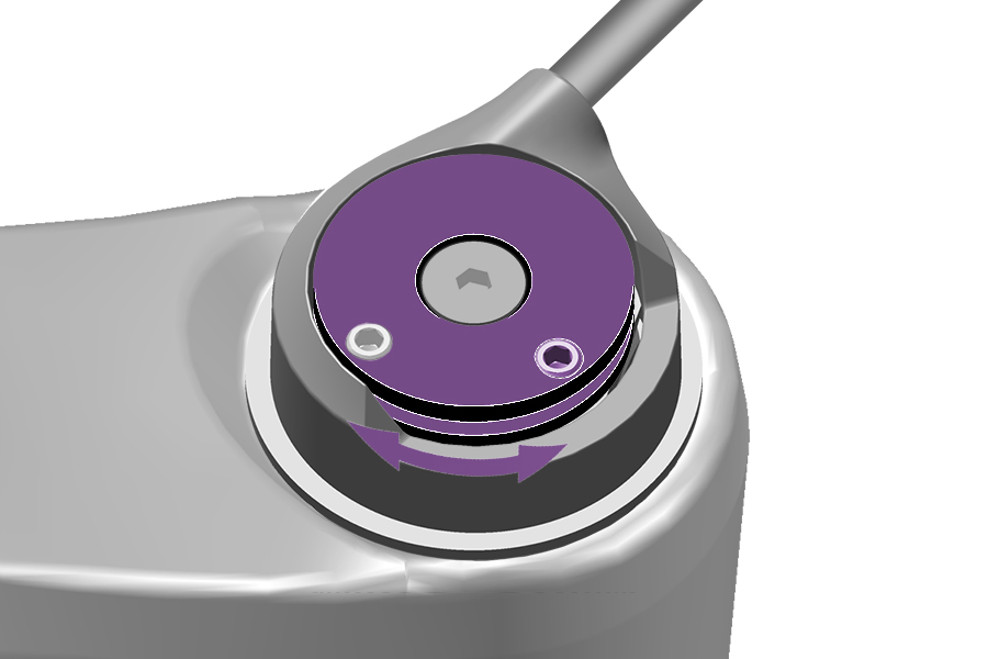
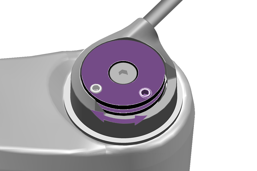
Threshold, (Pedal) position or Lock position can be actuated any time during use with the included cable or hydraulic remote on some RockShox rear shocks.
Consult the appropriate RockShox remote user manual at SRAM Service for installation and operation instructions.
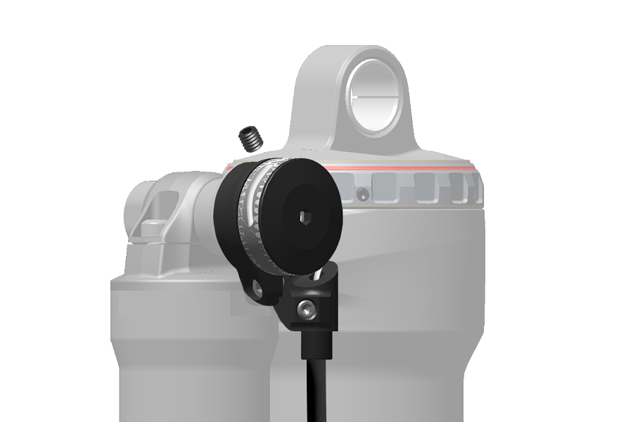
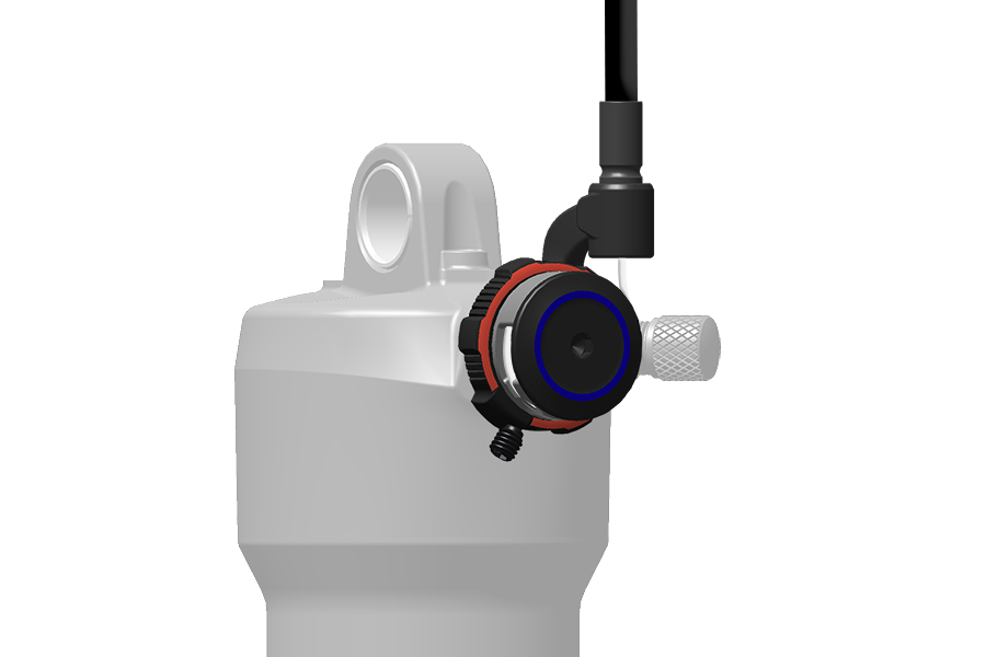
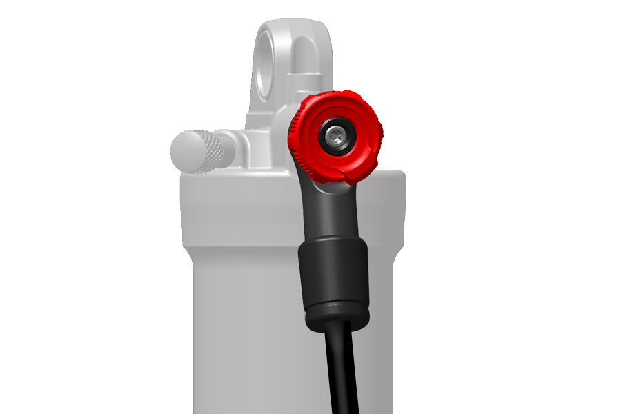
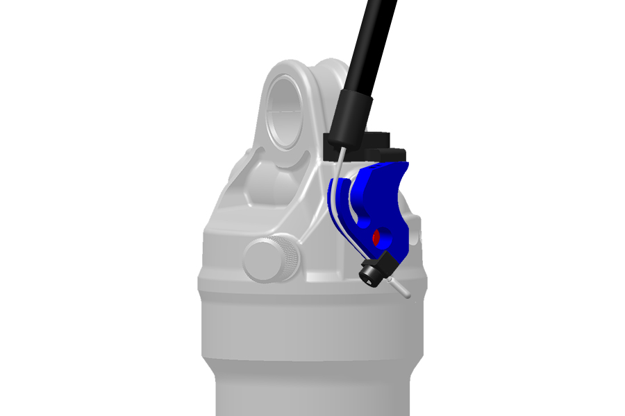

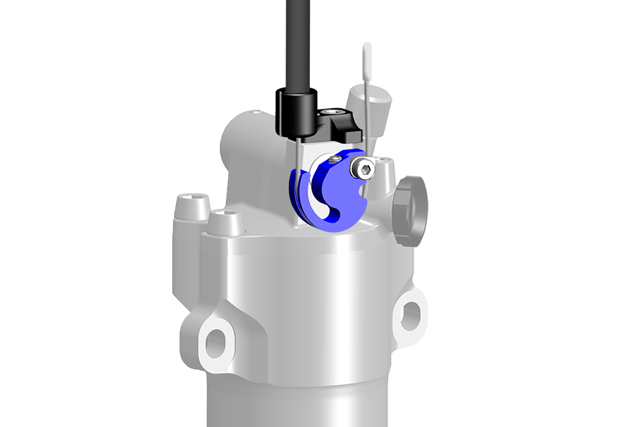
Some RockShox suspension forks feature Adjustable Bottom Out (ABO) which adjusts end-stroke spring ramp, or bottom out. ABO features a range of settings which move the position of the bottom out bumper to increase or decrease end-stroke spring compression resistance within the final 20% of fork travel.
Increased bottom out resistance which increases mid to ending stroke spring ramp without significantly affecting sag and small to medium bump sensitivity. Increased spring ramp at bottom out can be beneficial on larger drops or fast bumpy trails where the fork uses most of its travel.
If sag is set correctly and the suspension bottoms out quickly and often, try adjusting end-stroke bottom out with ABO until you find the preferred bottom out feel. ABO settings, Bottomless Tokens, and air spring pressure, as well as Low Speed Compression (LSC) and High Speed Compression (HSC) damping, affect beginning, mid, and end-stroke. Adjust each independently until the preferred performance is achieved.
Some Ultimate fork models feature externally adjustable ABO with a range of bottom out adjustment settings for maximum fine-tuning.
Some Select+ fork models feature internally adjustable ABO with three bottom out position settings.
Refer to RockShox for product details.
Refer to sram.com/service for ABO adjustment, upgrade, and service procedures.
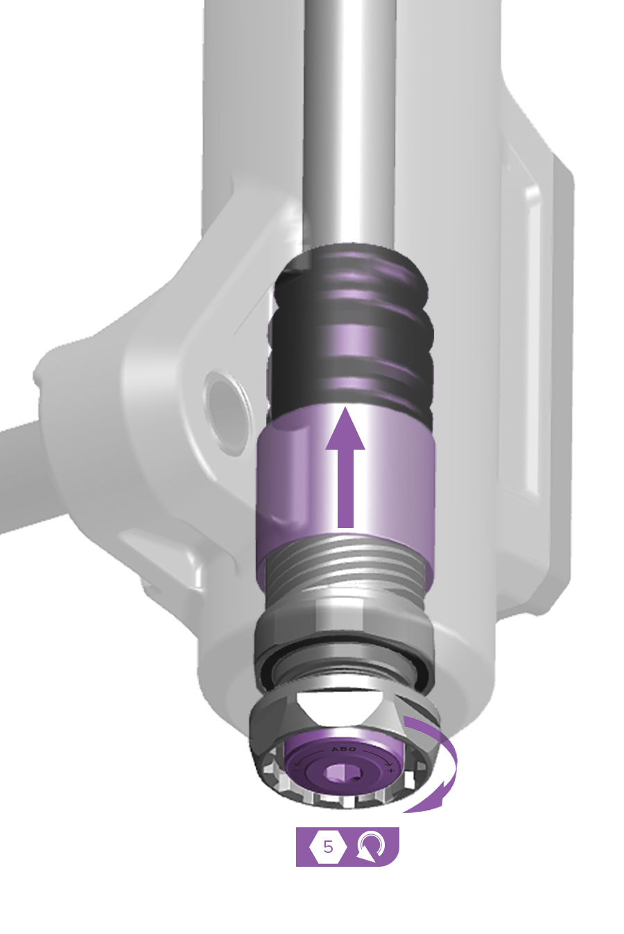
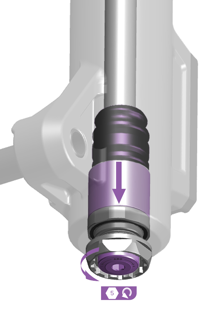
Rotate the external Adjustable Bottom Out (ABO) adjuster clockwise to increase end-stroke bottom out resistance.
Rotate the external Adjustable Bottom Out (ABO) adjuster counterclockwise to decrease end-stroke bottom out resistance.
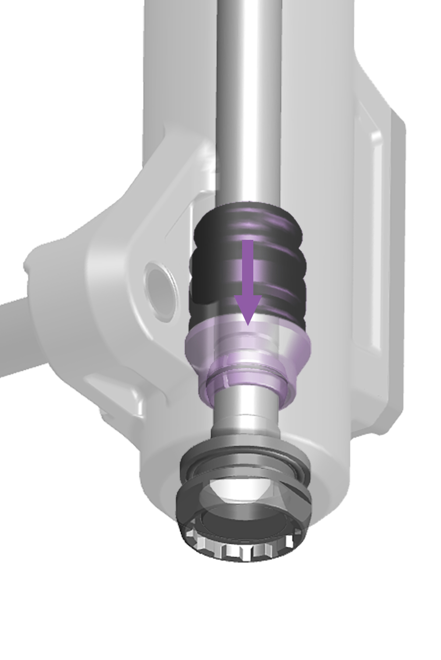
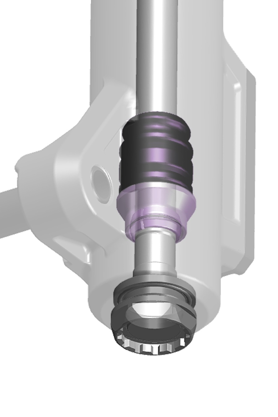
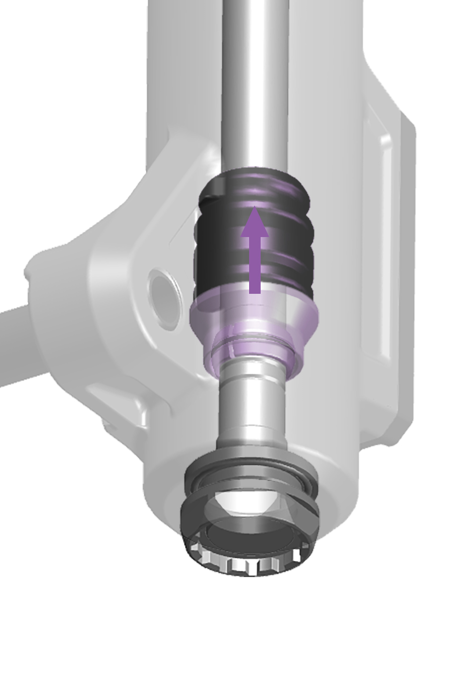
Internally adjustable ABO features three bottom out settings:
Lower Notch - Soft (least progressive)
Middle Notch - Medium (standard progression)
Upper Notch - Firm (most progressive)
To adjust bottom out for suspension forks featuring internally adjustable ABO, the fork lower leg must be removed.
Refer the fork service manual for your fork at sram.com/service for procedures.
Select RockShox rear shocks feature externally adjustable Hydraulic Bottom Out (HBO) which reduces harshness at bottom out. Adjustable Hydraulic Bottom Out (HBO) features 5 settings which restrict oil flow in the compression circuit within the final 20% of shock travel.
Increased hydraulic resistance (adjust HBO toward +) adds a hydraulic cushion that reduces harshness at bottom out which can be beneficial on larger drops and jumps.
Increase Hydraulic Bottom Out damping to fine-tune bottom out control depending on the terrain.
Spring, rebound damper, Low Speed Compression damper, and High Speed Compression damper settings may also need to be adjusted when Hydraulic Bottom Out adjustment is increased. Adjust each shock setting as needed for optimal settings and performance as riding speed and terrain require.
Refer to RockShox for more product details.
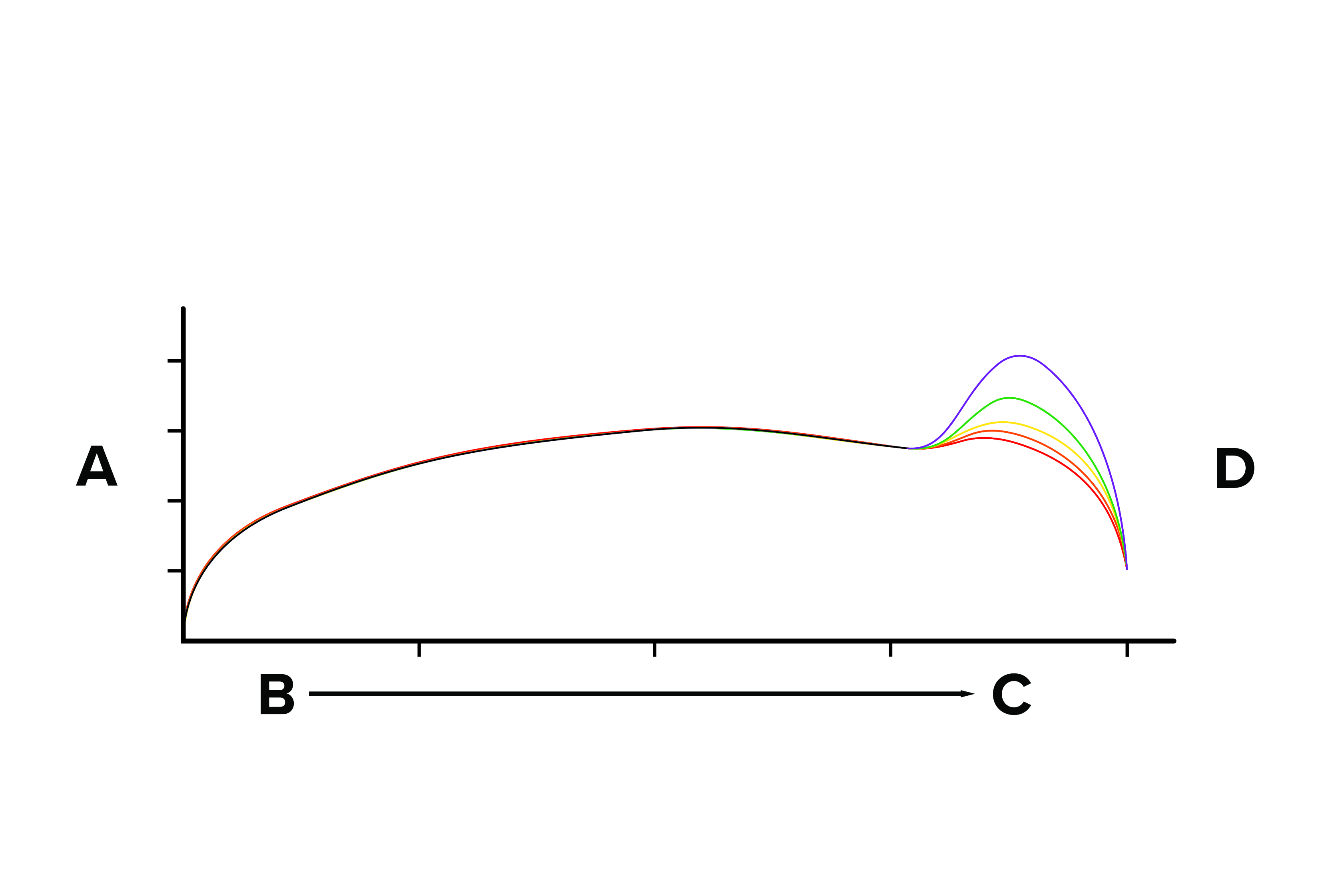
A | COMPRESSION FORCE |
B | COMPRESSION STROKE (SHOCK TRAVEL) - TOP OUT |
C | COMPRESSION STROKE (SHOCK TRAVEL) - BOTTOM OUT |
D | +4 CLICKS (CLOSED) - PURPLE |
D | +3 CLICKS - GREEN |
D | +2 CLICKS - YELLOW |
D | +1 CLICKS - ORANGE |
D | 0 CLICKS (OPEN) - RED |
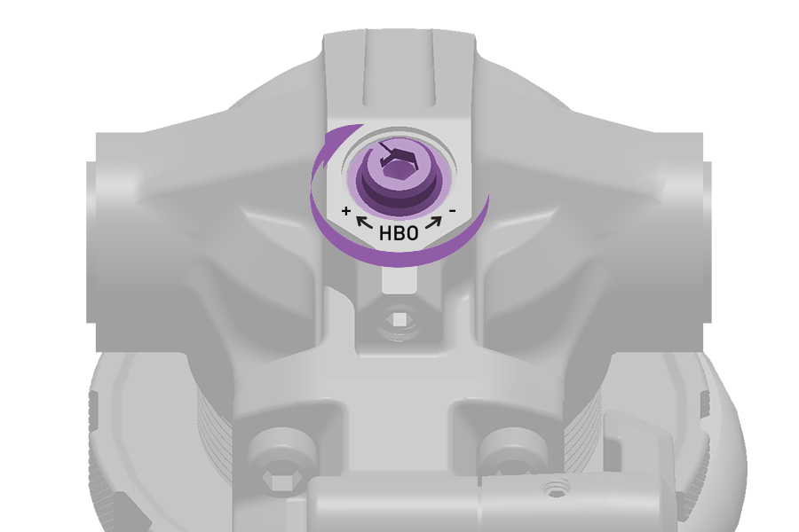
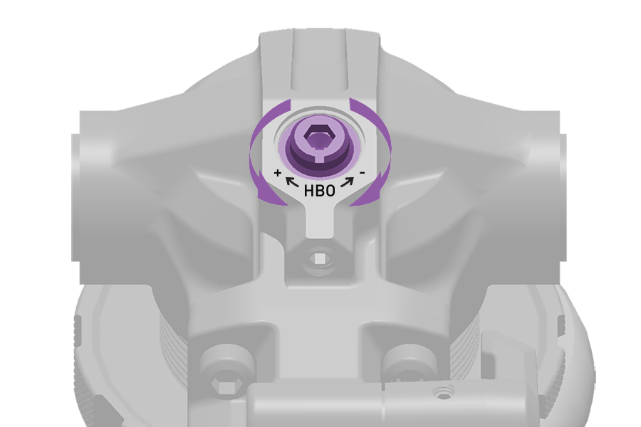
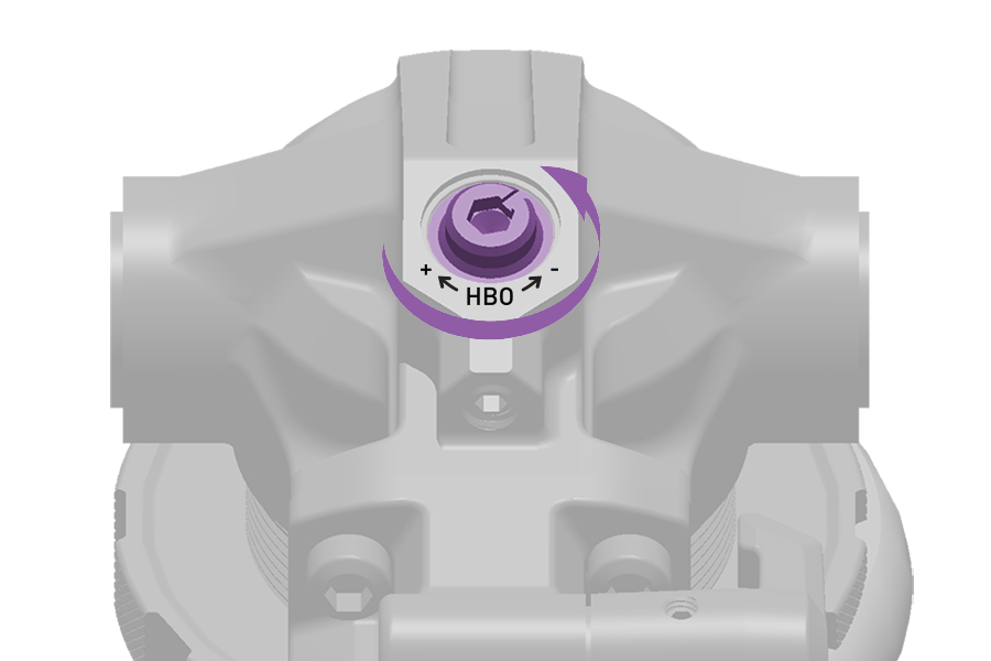
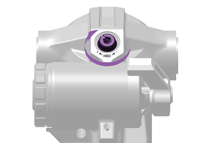
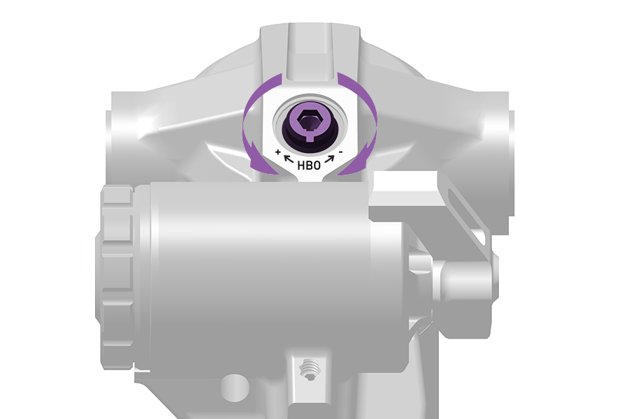
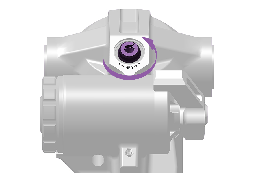
Select RockShox rear shocks feature externally adjustable Hydraulic Bottom Out (HBO or ABO) which reduces harshness at bottom out. Adjustable Hydraulic Bottom Out features 5 settings which restrict oil flow in the compression circuit within the final 20% of shock travel.
Increased hydraulic resistance, adjust HBO or ABO toward (+), adds a hydraulic cushion that reduces harshness at bottom out which can be beneficial on larger drops and jumps.
Increase Hydraulic Bottom Out damping to fine-tune bottom out control depending on the terrain.
Spring, rebound damper, Low Speed Compression damper, and High Speed Compression damper settings may also need to be adjusted when Hydraulic Bottom Out adjustment is increased. Adjust each shock setting as needed for optimal settings and performance as riding speed and terrain require.
Refer to RockShox for more product details.
HBO | ABO | |
|---|---|---|
A | COMPRESSION FORCE | COMPRESSION FORCE |
B | COMPRESSION STROKE (SHOCK TRAVEL) - TOP OUT | COMPRESSION STROKE (SHOCK TRAVEL) - TOP OUT |
C | COMPRESSION STROKE (SHOCK TRAVEL) - BOTTOM OUT | COMPRESSION STROKE (SHOCK TRAVEL) - BOTTOM OUT |
D | +4 CLICKS (CLOSED) - PURPLE | POSITION +2 (CLOSED) - PURPLE |
D | +3 CLICKS - GREEN | POSITION +1 - GREEN |
D | +2 CLICKS - YELLOW | POSITION 0 - YELLOW |
D | +1 CLICKS - ORANGE | POSITION -1 - ORANGE |
D | 0 CLICKS (OPEN) - RED | POSITION -2 (OPEN) - RED |
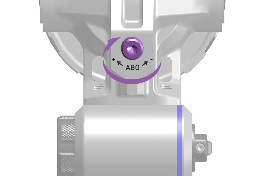
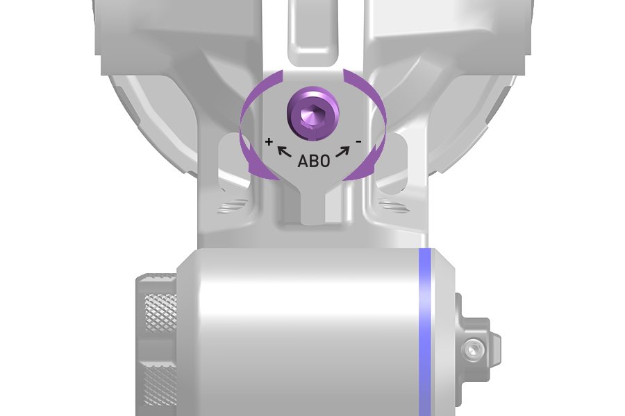
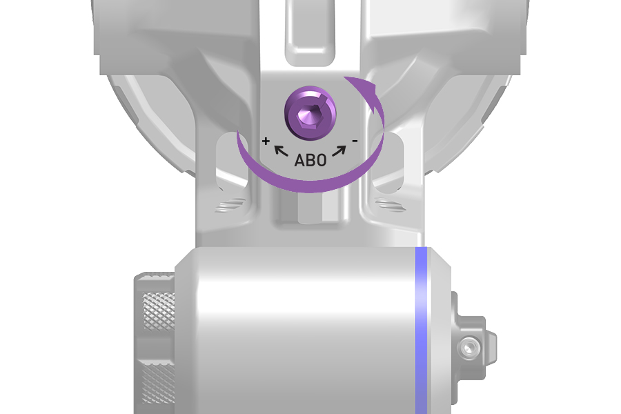
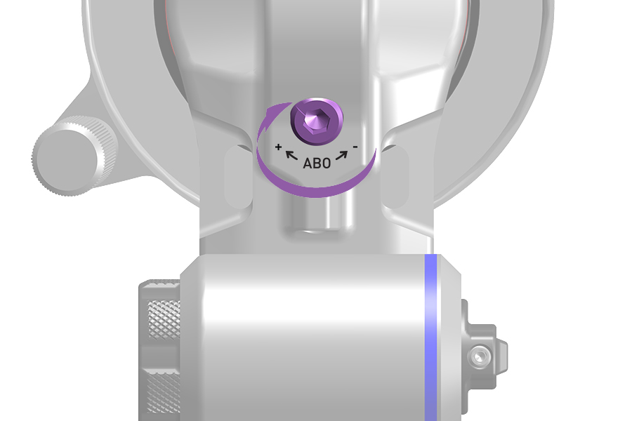
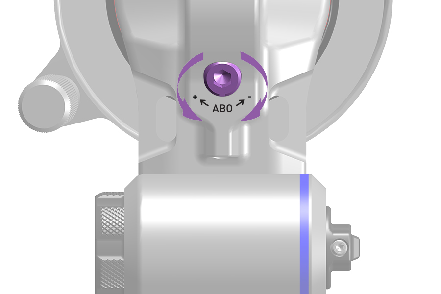
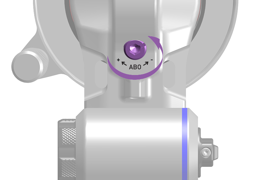
Clean your suspension fork with water and mild soap. Never use a high-powered washer to clean the suspension fork.
To maintain the high performance, safety, and long life of your suspension fork, clean the fork regularly, and perform routine maintenance.
Consult the front suspension service manual for your fork at sram.com/service for service interval schedules and procedures.
CRASH HAZARD: Do not use vinegar of any type to clean any part of a RockShox suspension product. Vinegar can cause permanent damage to parts which can, over time, result in product structural failure, serious injury, and possibly death.
Damage from abrasion is not covered under warranty. To avoid damage to lower leg paint and magnesium from abrasion, rinse the fork and fender with water after each ride. Periodically remove the fender, clean the fork and fender, and reinstall with new cable ties.
SINGLE CROWN FORKS
Consult your fork's service manual for service instructions for the following recommended service intervals at SRAM Service.
Every ride Clean the dirt and debris from the upper tubes and wiper seals, check air pressure, and inspect upper tubes for scratches.
Every 50 hours Perform lower leg service.
Every 200 hours Perform lower leg, damper, and spring service.
BOXXER (Gen D)
Consult your fork's service manual for service instructions for the following recommended service intervals at SRAM Service.
Every ride Clean dirt and debris from the upper tubes and wiper seals, check air pressure, inspect upper tubes for scratches, and confirm the Maxle DH is secure.
Every 25 hours Consult the fork's service manual for proper suspension fork fastener torque and confirm crown and lower leg bottom bolts are tightened to the specified torque.
Every 50 hours Perform lower leg service.
Every 100 hours Perform air spring lubrication service.
Every 200 hours Perform lower leg, damper, and spring service.
Suspension oil may appear on the damper body during or after use. This is normal lubrication necessary to the performance of the shock and is not a sign of decreased performance. Wipe off extra oil on the damper body or damper shaft to keep the system clean and perform regular service to ensure adequate lubrication oil remains in the system.
If the performance of the shock has changed drastically, check the damper body or damper shaft for scratches, the air can or damper shaft wiper seal for wear or deformation, and rotate the rebound to “full slow” or the compression to “Lock” to assess the damping performance. If either setting feels inconsistent or if you observe scratches on the damper body or damper shaft, contact your RockShox dealer for assistance.
Clean your shock with water and mild soap. Never use a high-powered washer to clean the shock.
To maintain the high performance, safety, and long life of your rear suspension, clean the shock regularly, periodically check the fastener torque values for compliance, and perform routine maintenance.
Consult the rear shock service manual for your shock at SRAM Service for service interval schedules and procedures.
CRASH HAZARD: Do not use vinegar of any type to clean any part of a RockShox suspension product. Vinegar can cause permanent damage to parts which can, over time, result in product structural failure, serious injury, and possibly death.
♻ For recycling and environmental compliance, please visit sram.com/en/company/about/environmental-policy-and-recycling
Consult your E-Bike Manufacturer for compact and full-size battery recycling information.
Replace the SRAM battery with an authentic SRAM battery only.
Replace the AXS Controller battery with a CR2032 coin cell battery only.
Replace the SRAM power meter battery with a CR2032 coin cell battery only.
Replace the Pedal Sensor battery with a AAA Lithium/Iron Disulfide (Li/FeS2) battery only.
Replace the SRAM or Quarq power meter Battery Sled battery with a AAA Lithium battery only.
Consult the SRAM Battery and Charger User Manual for battery maintenance and specifications.
Never dispose of batteries in a fire.
