General Safety

Safety First!
We care about YOU. Please, always wear your safety glasses and protective gloves when servicing SRAM products. Protect yourself! Wear your safety gear!


Safety First!
We care about YOU. Please, always wear your safety glasses and protective gloves when servicing SRAM products. Protect yourself! Wear your safety gear!
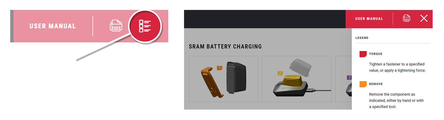
Click on the icon at the top right corner of the screen to display the color legend and the complete list of tools and supplies for this manual in a scrollable dropdown list.
The colors and symbols featured in this manual correspond to specific actions or procedures. A detailed description for each color and symbol is contained in the dropdown.
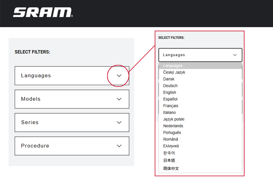
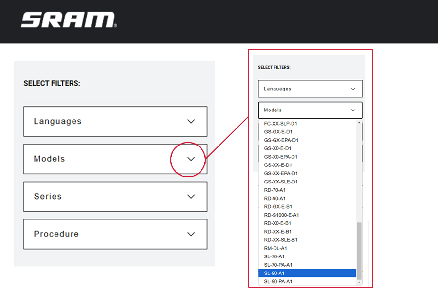
Use the dropdown lists in the SELECT FILTERS: window at the top left of the page to select the preferred language, product model code, and instructional content. Product instructional content filters will vary.
Language Filter: Select Language first. When a new language is selected, all other selected filters will reset.
All non-Language Filters: To reset a non-language filter, click on the X.
Product model code and specification details can be identified with the serial number on the product. Model codes can be used to identify the product type, series name, model name, and product version associated with the production model year. Product details can be used to identify spare parts, service kit, and lubricant compatibility.
SRAM Model Code example: DS-OCHN-X-B1
DS = Product Type - Damper Spider
OCHN = Platform - Ochain
X = Model - X
B1 = Version - (B - First generation, 1 - first iteration)
To identify the model code, locate the serial number on the product and enter it into the Search by Model Name or Serial Number field at www.sram.com/service.
Your product's appearance may vary from those pictured in this manual.
Images and examples pictured are for conceptual purposes and may vary from product design, appearance, and performance.
Consult sram.com/service whenever a separate manual is referenced in this document.
Read the full warranty policy for your components at sram.com/en/service/warranty.
For information about trademarks used in this manual, visit sram.com/website-terms-of-use.
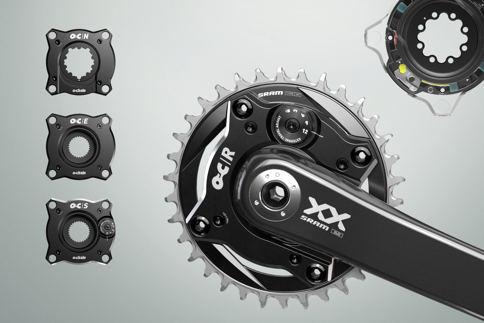
Ochain is a 1 x 104 mm bolt circle diameter (BCD) spider damper that replaces the current spider on the crank or direct mount chainring.
Ochain allows the chainring to rotate rearward to disengage the transmission from the rider and chassis, improving the riding experience and bicycle performance by reducing noise and pedal feedback, allowing for greater chassis stability and fewer distractions.
Ochain R and S offer an External Travel Adjustment system to allow for instant external degree adjustment.
Ochain N and E offer travel chip kits in degrees of rotation: 6°, 9° (default), and 12°. These models can both be upgraded using the appropriate Ochain upgrade kit (N to R) or (E to S). Consult Ochain Upgrade section for more information.
9° travel chip will be installed and can be changed by purchasing a travel chip kit and consulting the Internal Adjustment - Ochain E section of this manual.
Ochain spiders are not compatible with every frame and every crankset on the market.
You must choose an Ochain spider that maintains the chainline of your bicycle frame. Consult the Compatiblity section of this manual to determine which Ochain spider and configuration is compatible with your bicycle components.

*The Ochain E and Ochain S spiders replace the the original direct mount e-MTB chainring.
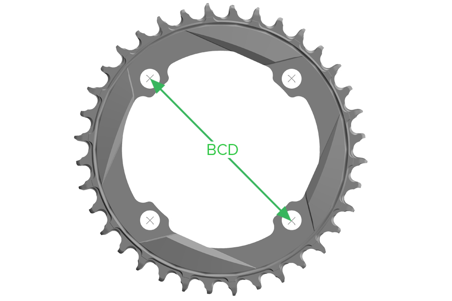
The Bolt Circle Diameter (BCD) is the diameter of the circle that goes through the center of the bolts on the chainring.
Ochain models are only compatible with 104 BCD chainrings.
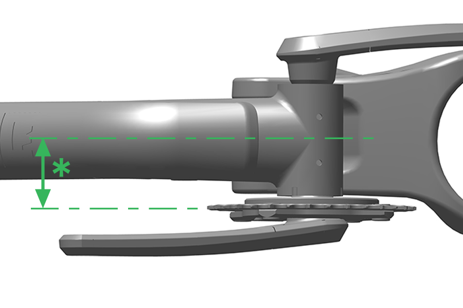
Consult your bicycle frame manufacturer to determine the chainline of your bicycle. Chainline is the distance between the centerline of your frame and the centerline of your chainring.
Ochain spiders come standard with a 3 mm offset. Chainline adjustment kits are available to increase offset as needed. When making adjustments to the offset with spacers or adding the bashguard, the proper length chainring bolt must be used. Review the options below to identify the proper length chainring bolt and nut.
Configuration | Chainring Bolt and Nut Length |
|---|---|
3 mm offset (Spider) | Short Bolt (4.6 mm) and Short Nut (6.2 mm) |
Bosch BDU38 - Ochain Spider E and S only (Gen B) (Spider) | Short Bolt (4.6 mm) and Short Nut (6.2 mm) |
6 mm offset (Spider + 3 mm Spacer) | Long Bolt (6.8 mm) and Long Nut (8.5 mm) |
3 mm offset (Bashguard* + Spider) | Long Bolt (6.8 mm) and Long Nut (8.5 mm) |
6 mm offset (Bashguard + Spider + 3 mm Spacer) | Not Compatible - See warning below |
*When using the Ochain EASY Bashguard, only two sets of Long bolts and Long nuts are required. Install Short bolts and Short nuts in the remaining bolt holes where the bash guard is not present.
Part Name | Part Description | Part Number |
|---|---|---|
Spacers and bolt kit | Four 2 mm spacers and four 3 mm spacers, long and short mounting hardware Alu M8.5X075) – compatible with Bosch DU37, DU38, DH, std chainline | 11.6118.082.011 |
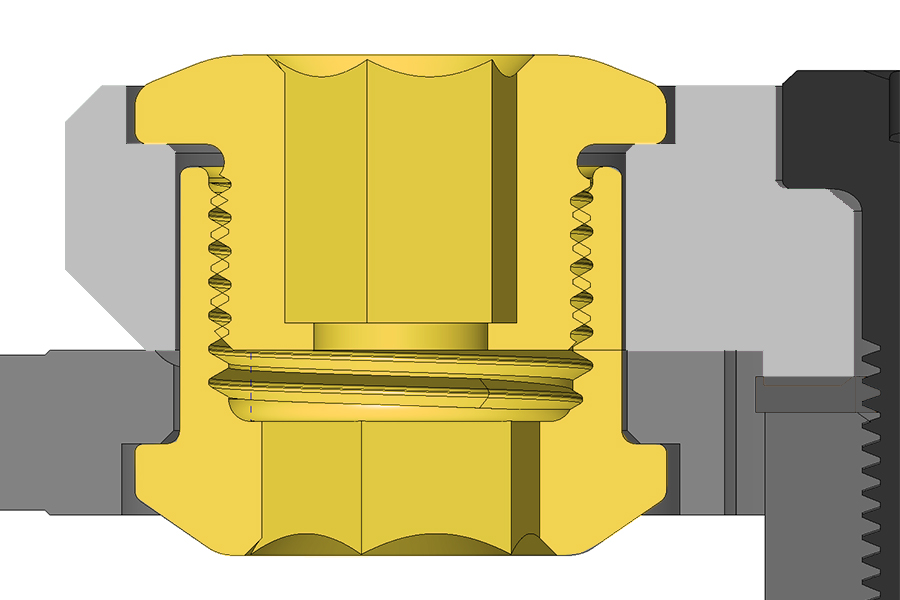
Short Chainring Bolts and Nuts
When installing the chainring directly to any Ochain Spider (R, S, N, E) for a 3 mm offset, use the Short Bolt and Nut only.
This bolt and nut configuration applies to Bosch BDU38.
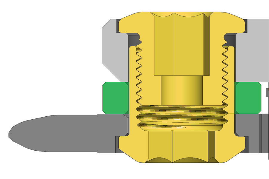
Long Chainring Bolts and Nuts
When installing the chainring onto any Ochain Spider (R, S, N, E) with any spacers or bashguard*, you must use the Long Chainring Bolts and Nuts.
*When using the Ochain EASY Bashguard, only two sets of Long bolts and Long nuts are required. Install Short bolts and Short nuts in the remaining bolt holes where the bashguard is not present.
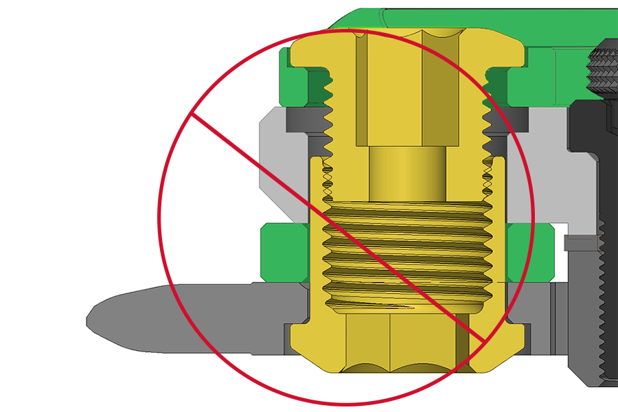
CRASH HAZARD: This configuration does not allow enough thread engagement to properly hold your Ochain to your chainring. Riding with insufficient thread engagement can cause the bolt to disengage which can cause the rider to lose control and crash, resulting in serious injury and/or death.
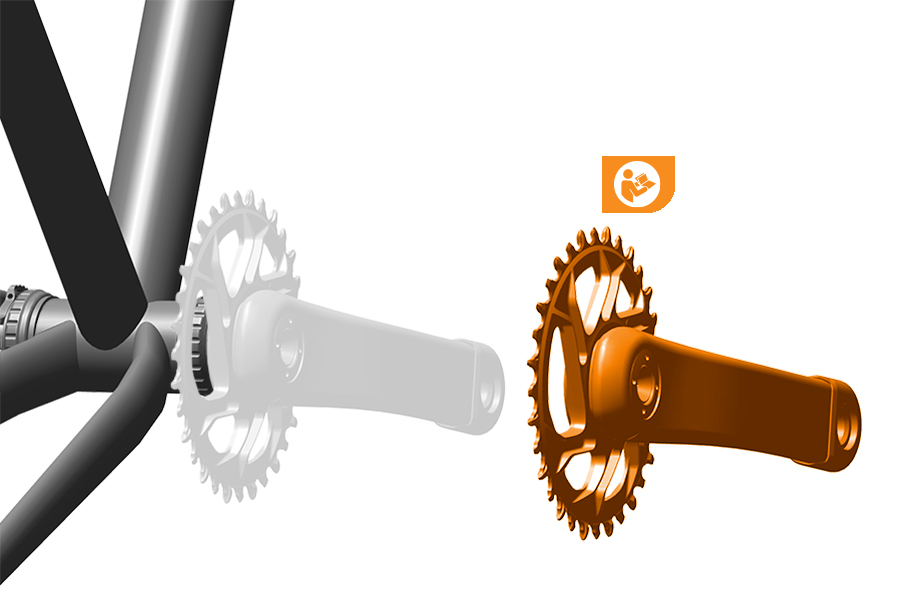
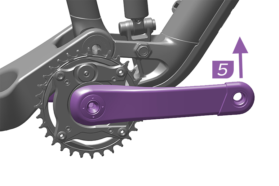
Crankset Removal
Remove the crankset by consulting the manufacturer's instructions.
If you are removing a SRAM Dub Crankset consult the DUB Cranksets and Bottom Brackets User Manual.
E-Bike Crankset Removal
Remove the crankset from the motor and remove the original chainring from the motor axle according to the manufacturer’s instructions.
For information on which size chainring bolts and nuts to use, refer to the Compatibility - Chainring Bolts section.
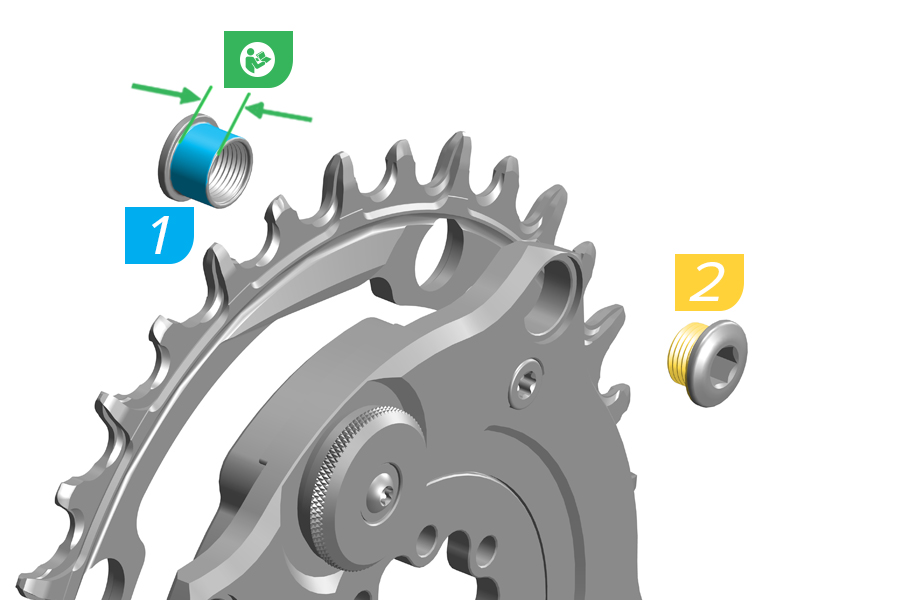
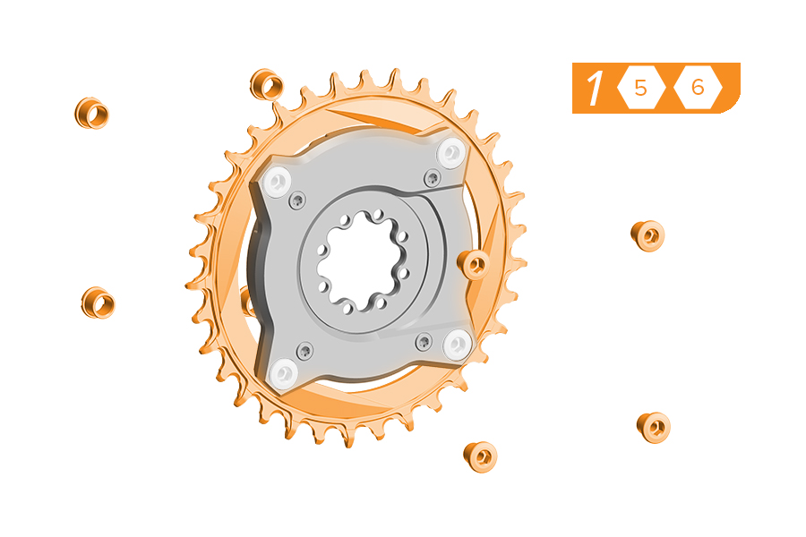
1. Apply grease to the outside of the four chainring nuts.
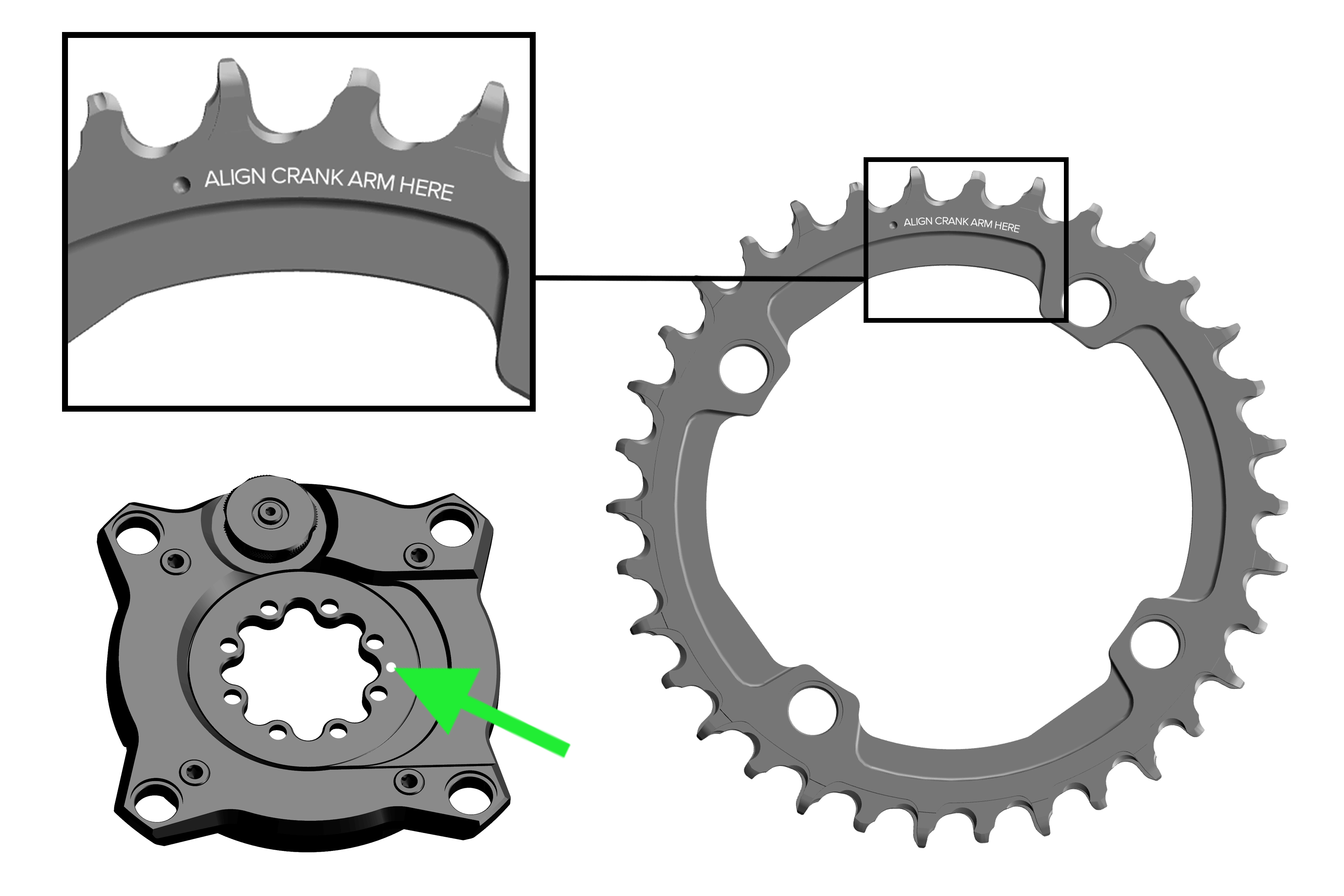
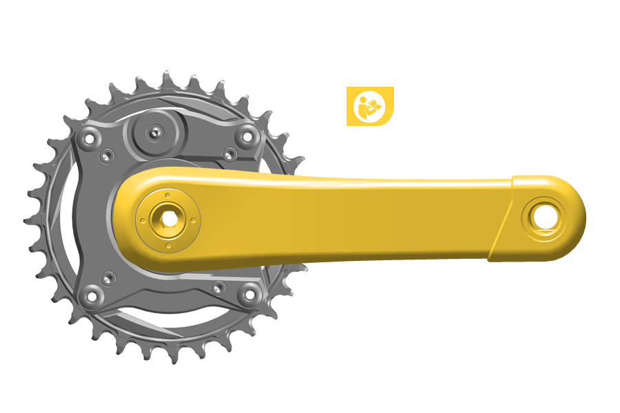
Align the crank arm with the indented dot reading 'align crank arm here' with the white dot on the front of Ochain.
CRASH HAZARD: Do not apply grease to the chainring nut or bolt threads.
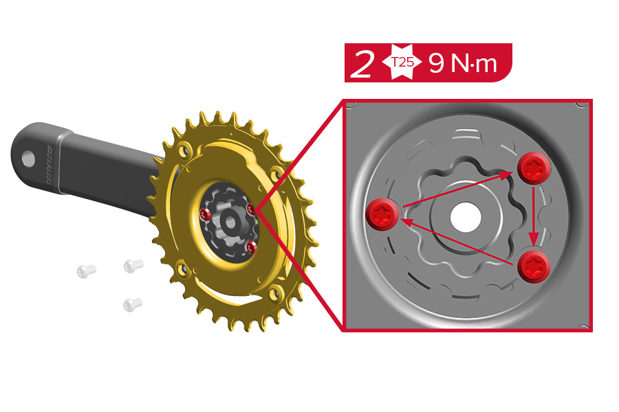
2. If reusing bolts, clean the bolts and reapply threadlocker on the four chainring bolts.
Chainring bolts are factory treated with a one-time-use threadlocker patch to help maintain preload in bolts. If bolts are removed from the crankset, the remaining threadlocker must be removed from the bolts and new medium compound threadlocker (such as Loctite Blue 242) must be applied.
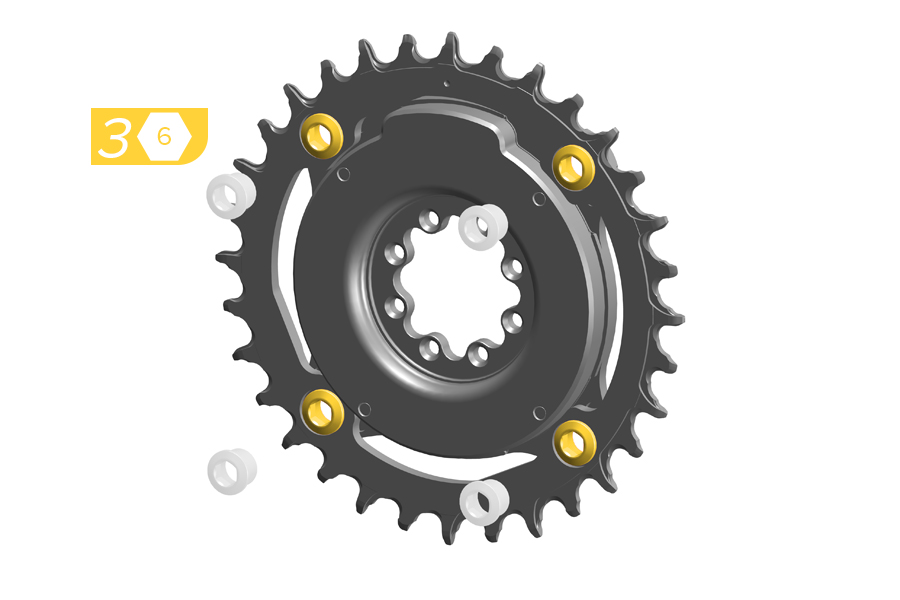
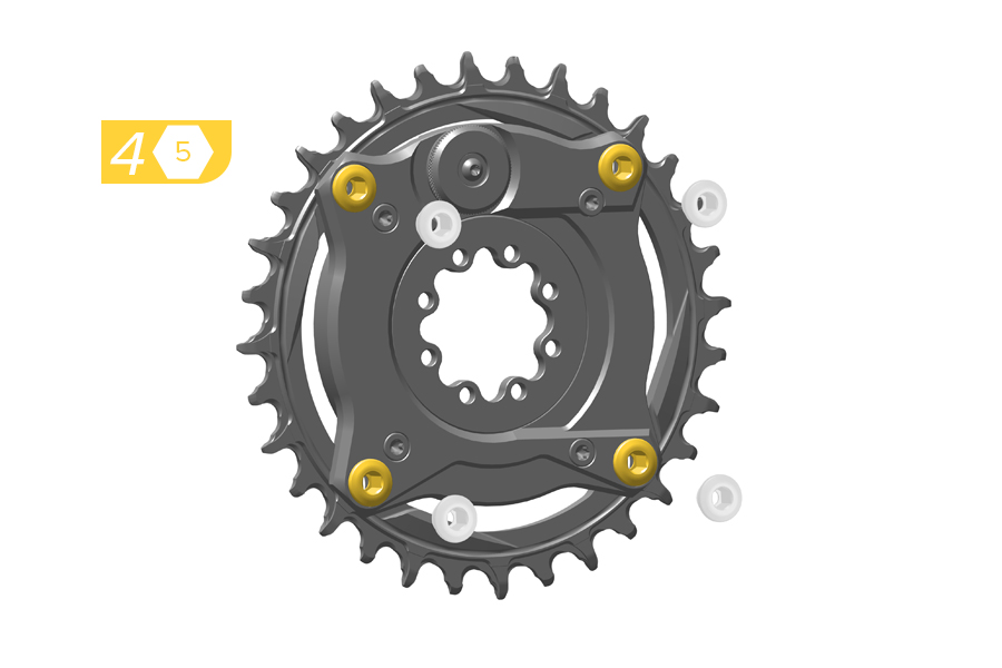
3. Install the Ochain spider onto the chainring using four appropriately sized chainring nuts.
4. Install the four chainring bolts into the chainring nuts.
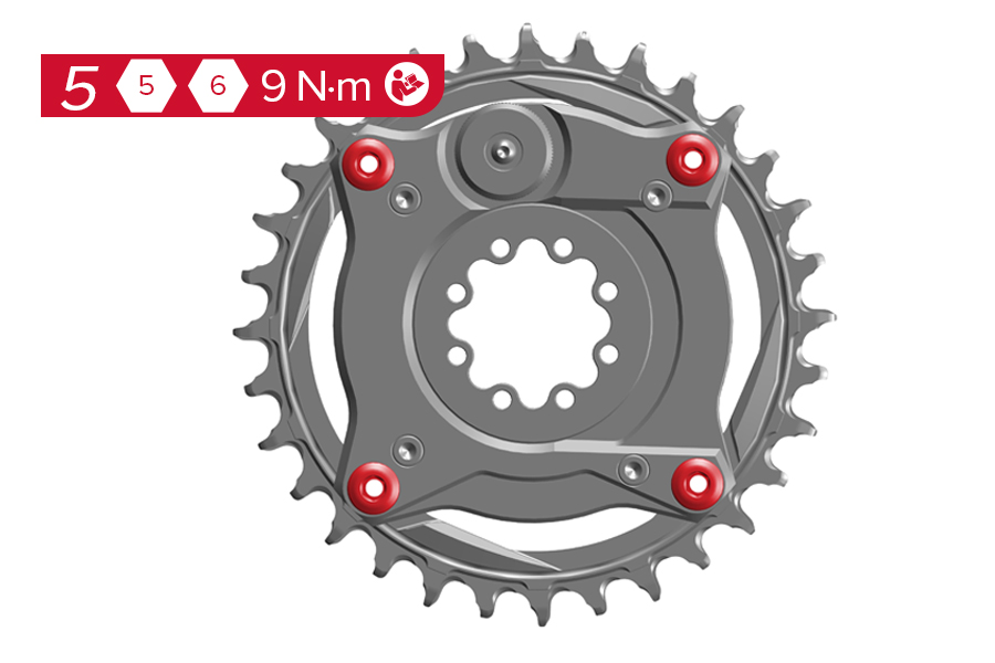
5. Tighten the four chainring bolts into the chainring nuts to the manufacturer’s specified torque. If using SRAM bolts, tighten to 9 N·m.
Crash Hazard - After the first ride, retighten the chainring nuts to 9 N·m. Routinely check the chainring nuts to verify torque. Improper chainring nut torque can cause the chainring to loosen, which can cause the rider to crash resulting in serious injury and/or death.
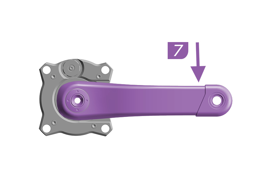
8 Bolt
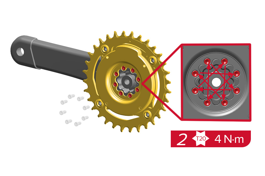
Install the crank arm to the Ochain spider according to the crank arm manufacturer's instructions.
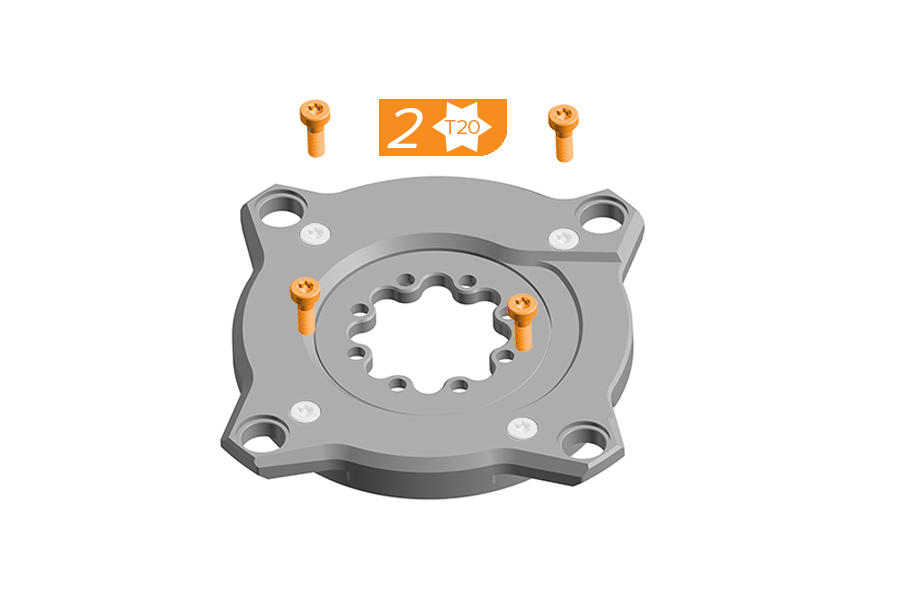
3 Bolt
Install the crank arm to the Ochain spider according to the crank arm manufacturer's instructions using the 3 bolts provided.
Only the use the three bolts provided with the Ochain spider. Do not use the original bolts included with the crank.
Install the crankset onto your bike frame according to the manufacturer’s instructions.
The Ochain logo will be facing away from the bicycle when correctly installed to the crank arm.
Ochain E and S will be compatible only on Bosch BDU 38 (Gen 5).
Before installing the Ochain spider, verify there is no plastic spacer between the original spider and the motor. If a plastic spacer is installed, remove it before installing the Ochain spider.

Installation
Refer to manufacturer's instructions for removal and installation.

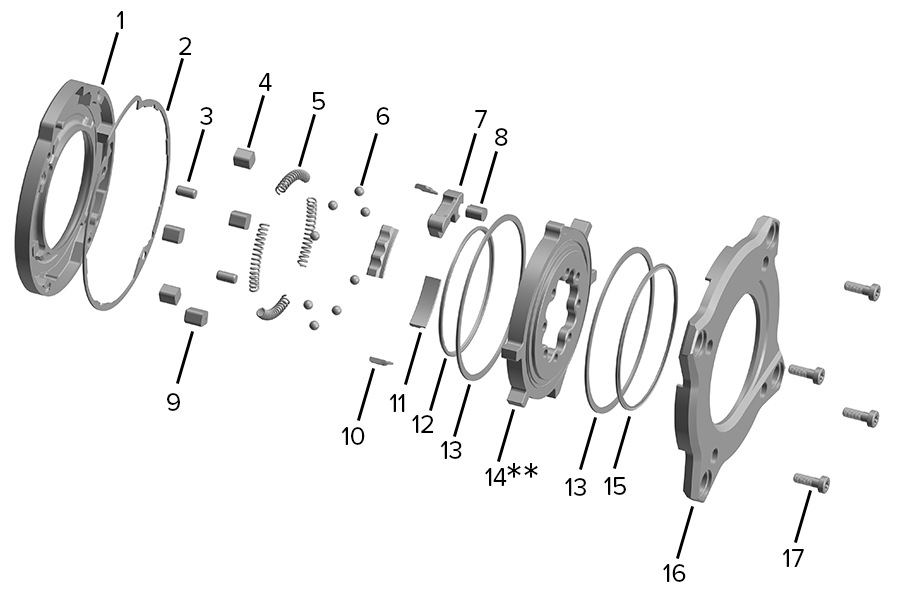
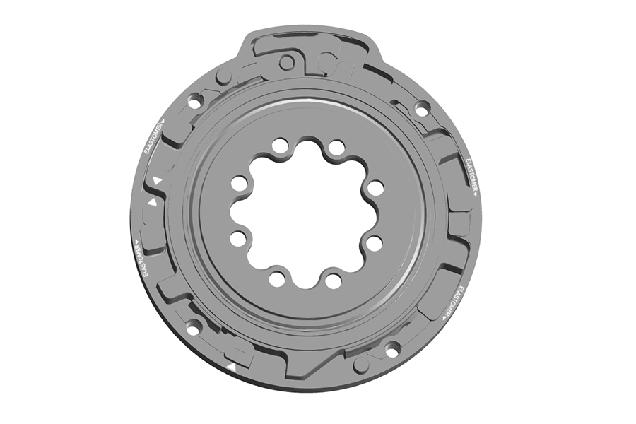
1. Backplate | 9. Internal Seal* | 17. m4 Screw (4x)* |
2. Rubber Gasket* | 10. Internal Spider Ring (2x)* | 18. Toothed Shaft* |
3. Rack* | 11. Internal Spider | 19. Spring* |
4. Rack Elastomer* | 12. External Seal* | 20. Knob* |
5. Elastomer (4x)* | 13. Alignment Pin (2x)* | 21. Washer* |
6. End Stroke Token* | 14. Bushing Narrow (2x)* | 22. O-ring* |
7. Spring (4x)* | 15. Bushing Wide (2x)* | 23. m3 Screw* |
8. Steel Ball (8x)* | 16. Cover* |
*Replaceable part; see the latest SRAM Spare Parts Catalog.
1. Backplate | 7. Travel Chip* | 13. Internal Spider Ring (2x)* |
2. Rubber Gasket* | 8. Rack Elastomer* | 14. Internal Spider |
3. Alignment Pin (2x)* | 9. End Stroke Token* | 15. External Seal* |
4. Elastomers (4x)* | 10. Bushing Narrow (2x)* | 16. Cover* |
5. Springs (4x)* | 11. Bushing Wide (2x)* | 17. m4 Screw (4x)* |
6. Steel Ball (8x)* | 12. Internal Seal* |
*Replaceable part; see the latest Spare Parts Catalog.
Ochain R and Ochain S models feature the External Travel Adjustment, which allows for simple adjustment to the desired degree of rotation. Refer to the table below to determine your starting point and adjust as necessary.
If pedaling is the priority, choose a lower setting. If gravity performance is the priority, choose a higher setting.
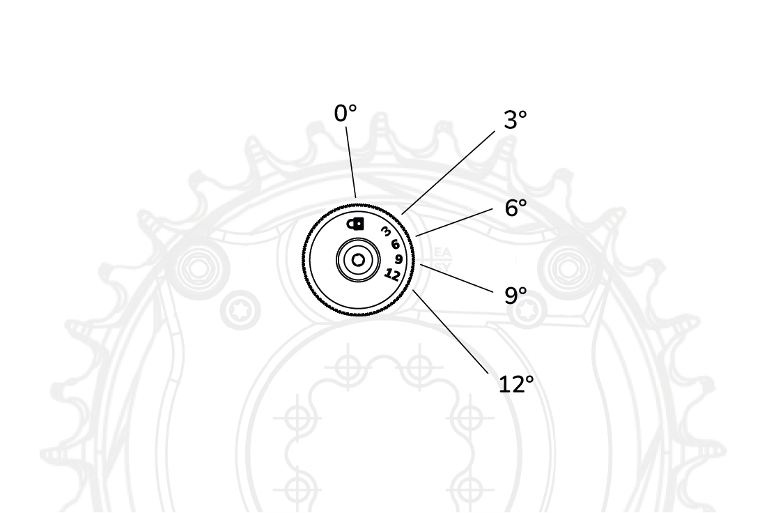
Angle | Ride Style | Terrain Type |
|---|---|---|
0° | Lock position for back to back comparisons. | |
3° | XC/Trail | Smooth, hardpack trails. Flowy compressions. Limited braking bumps. |
6° | Trail/Enduro | Medium rough trails. Some rocks and roots. Some braking bumps. |
9° | Enduro/Bike Park/DH | Rough trails. Rocky and rooty. Consistent braking bumps. |
12° | Bike Parks/DH | Extremely rough, loose trails. Largest compressions, where damage risk to wheels/tires is present. |
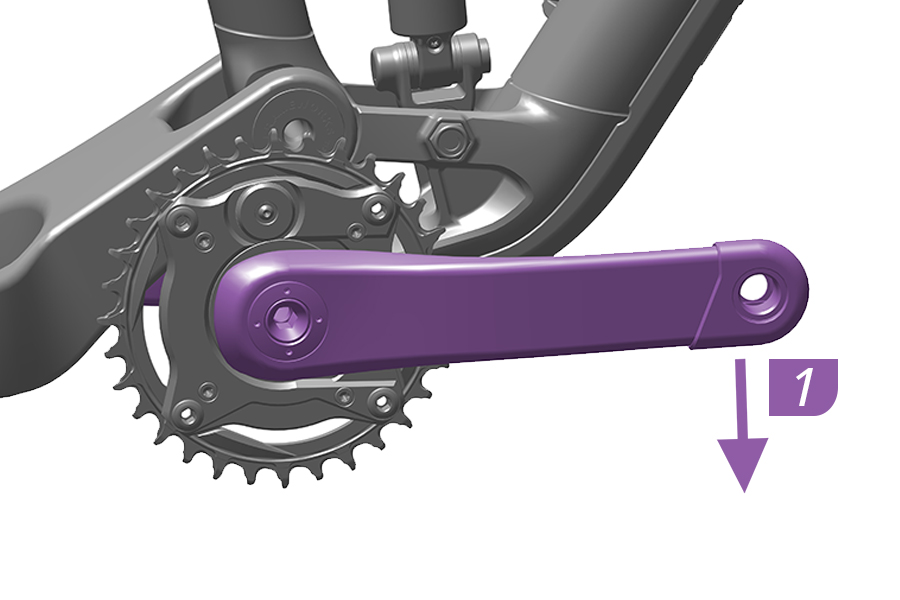
1. Push and hold the crank arm in the pedaling direction to engage the Ochain spider.
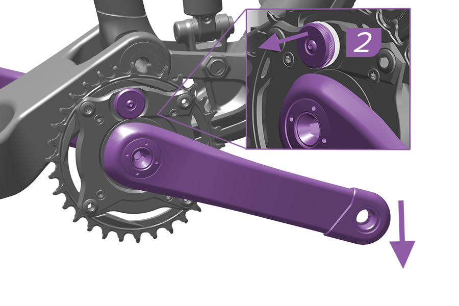
2. While continuing to press down on the crank arm, pull the adjustment knob out to reach the adjusting position.
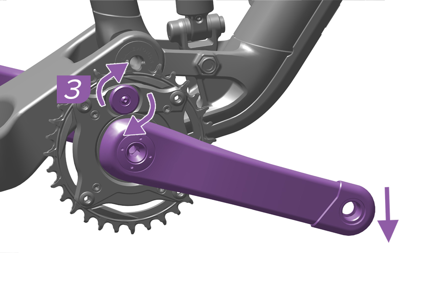
3. While continuing to hold the knob out in the adjusting position and pushing down on the crank, rotate the knob to the desired setting.
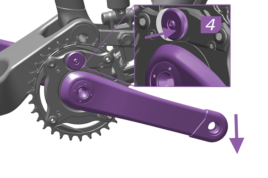
4. Release the knob and check that is in original position.
5. Release the crank.
The Ochain spider is adjusted and is ready for use.
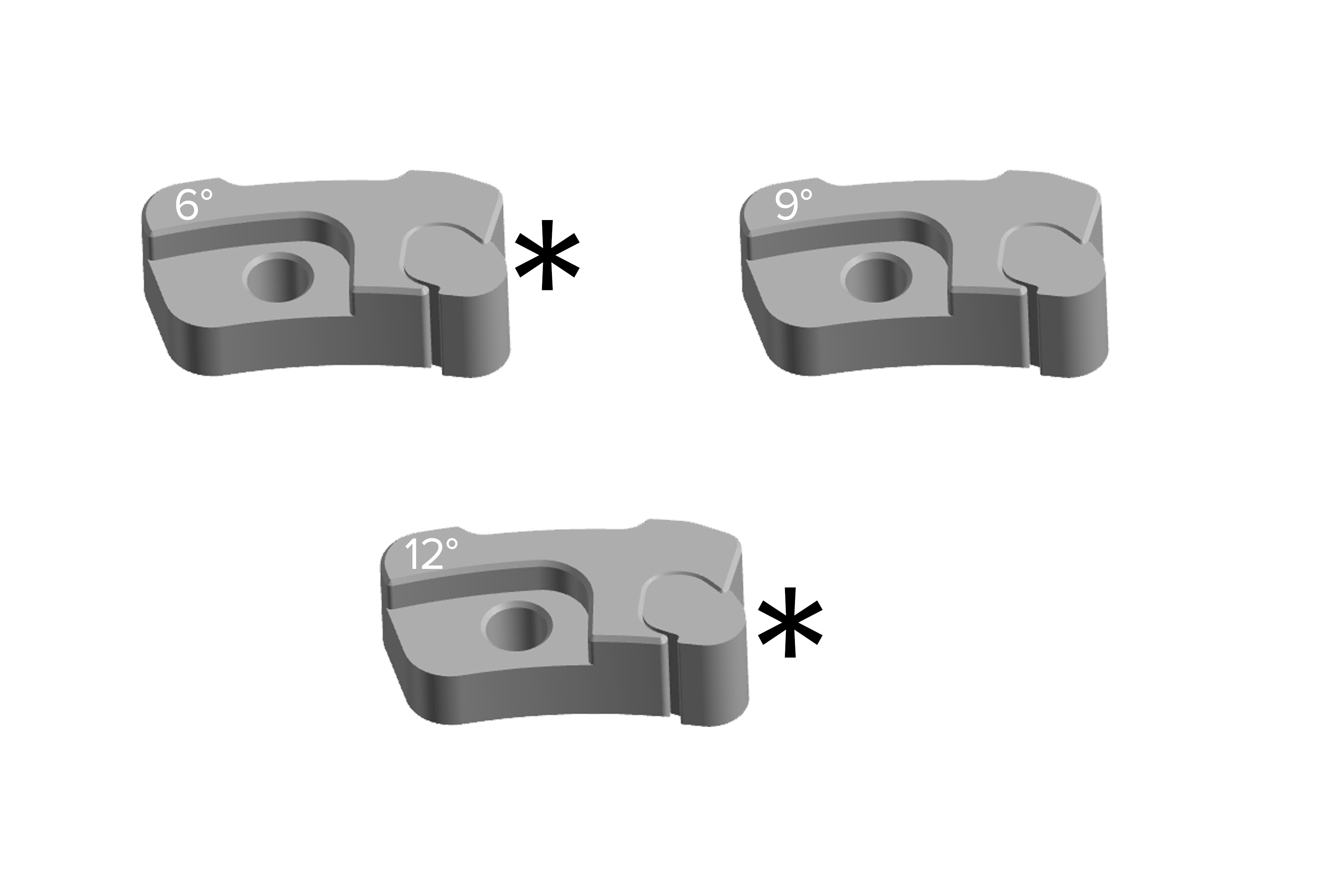
Ochain N and E spiders come equipped with a 9° travel chip installed.
The travel chip can be changed to 6° and 12° options. Travel chip kits are sold separately.
Internal Adjustment Procedure
Ochain Model N is pictured in this section.
Remove the crankset from the bicycle and remove the Ochain spider from the crankset prior to performing service.
1. Remove the chainring from the Ochain spider by removing the four chainring nuts and bolts. Use a damp cloth to wipe off any dirt and debris from the Ochain spider.
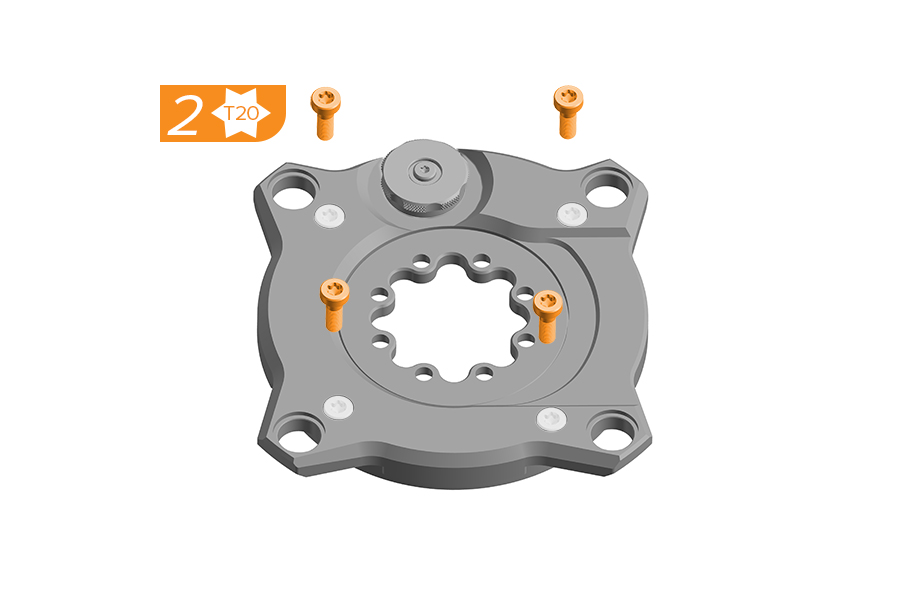
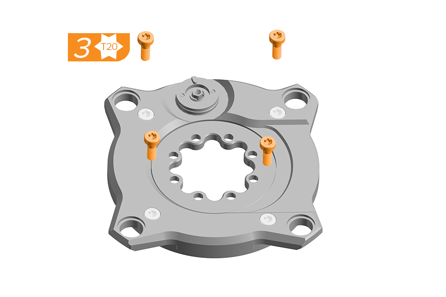
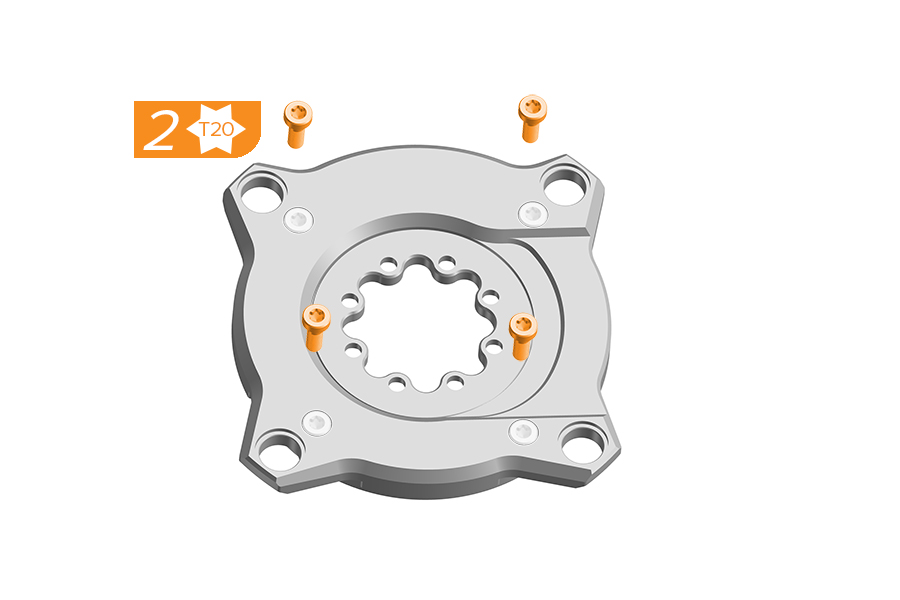
2. Place the Ochain spider face up on a flat, stable working surface. Remove and discard the four screws.
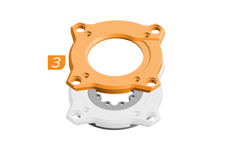
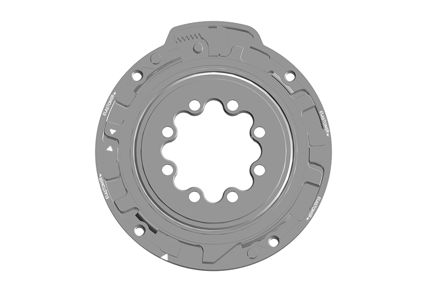
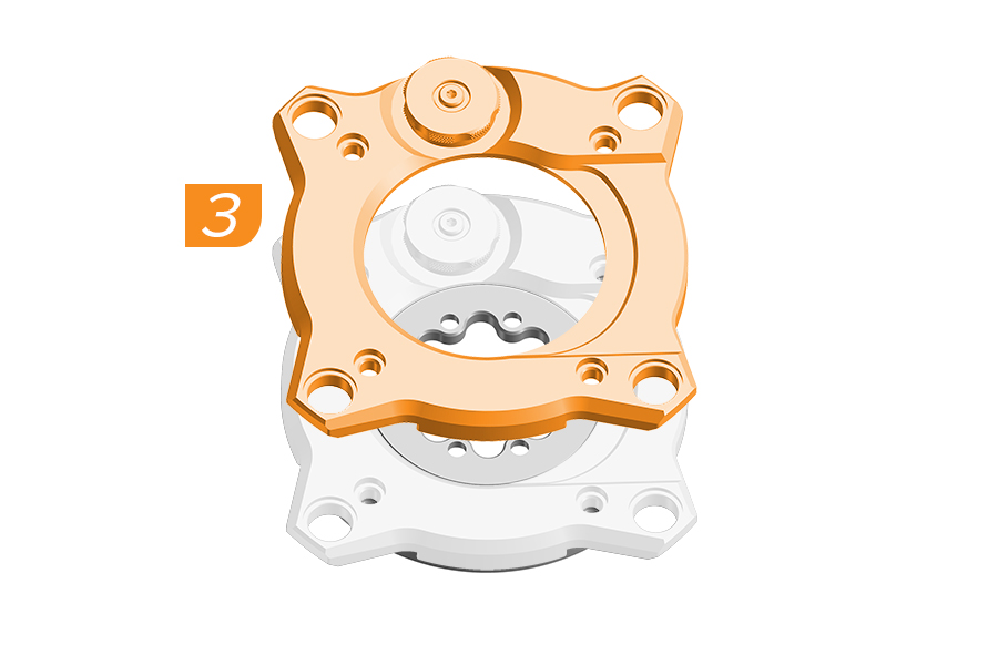
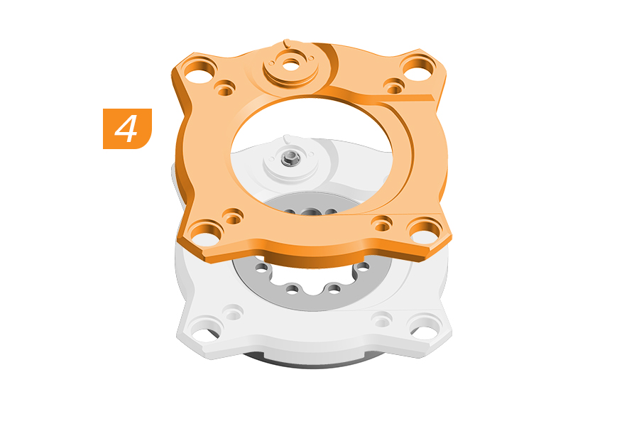
3. Carefully lift and remove the cover of the Ochain spider so that the internal components stay in position. Clean all surfaces with a clean cloth to remove dirt and old grease.
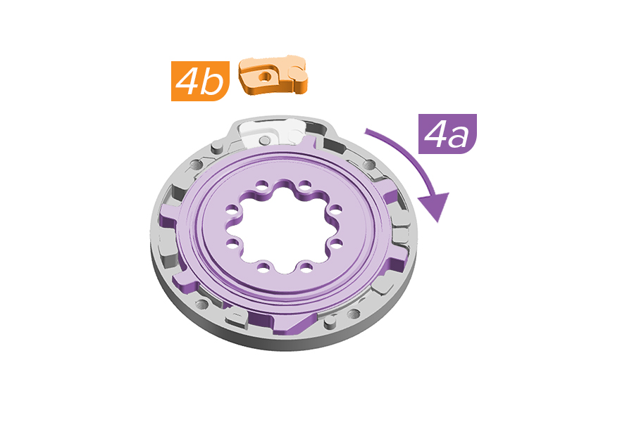
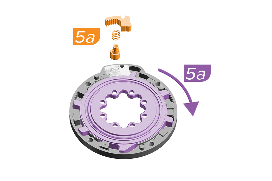
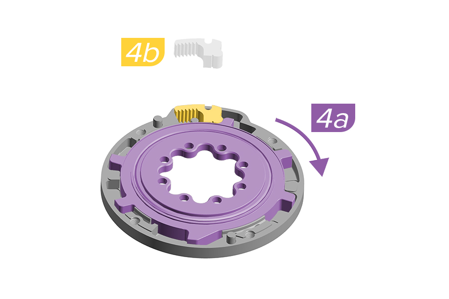
4a. Rotate the internal spider using the crank arm.
4b. Push down on the internal spider with hand or crankarm and use pliers to remove the travel chip from the backplate.
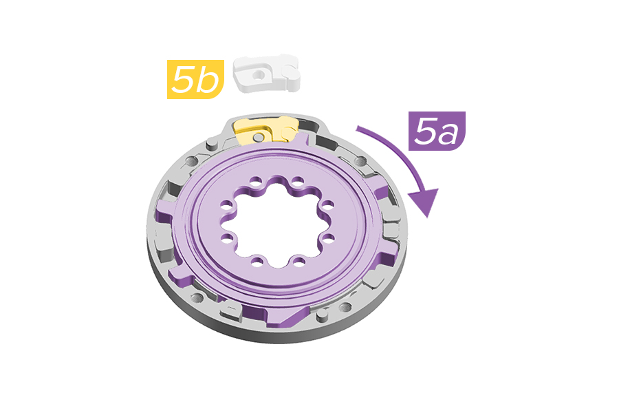
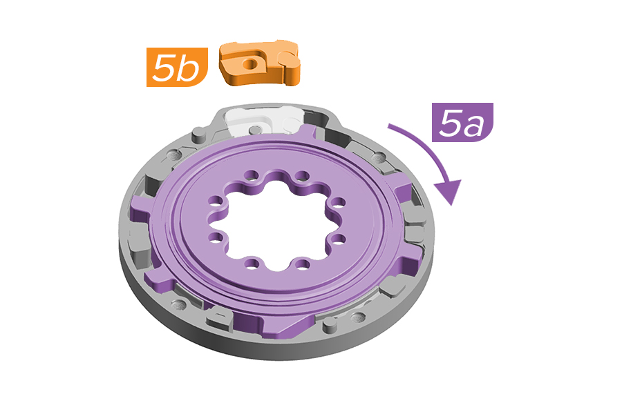
5a. Rotate the internal spider using the crank arm a few degrees to allow for travel chip install.
5b. Install the new travel chip etched with your intended degree of rotation. Push the travel chip down fully into position in the backplate.
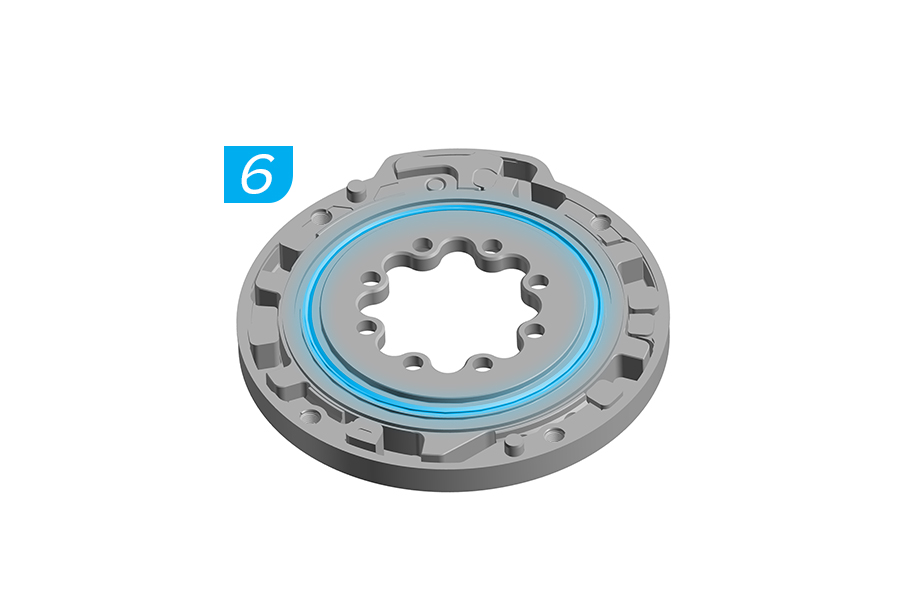
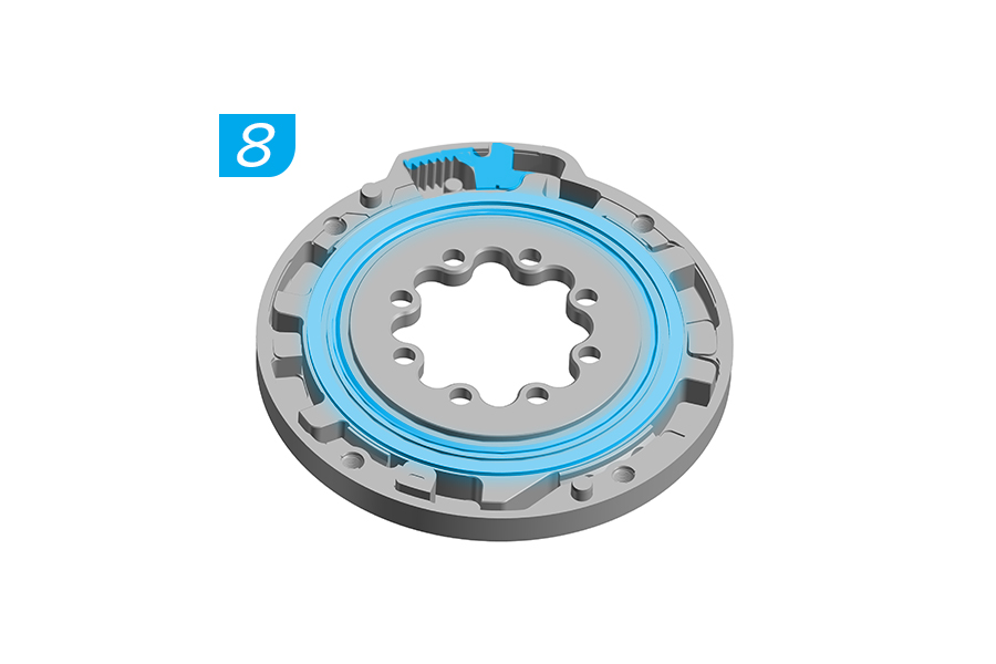
6. Apply lithium based grease around the internal seal.
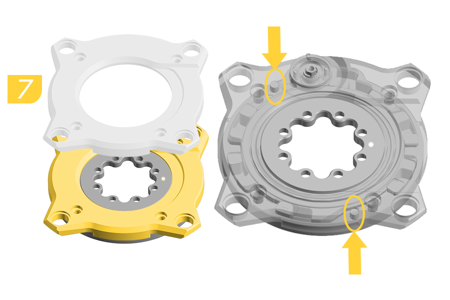
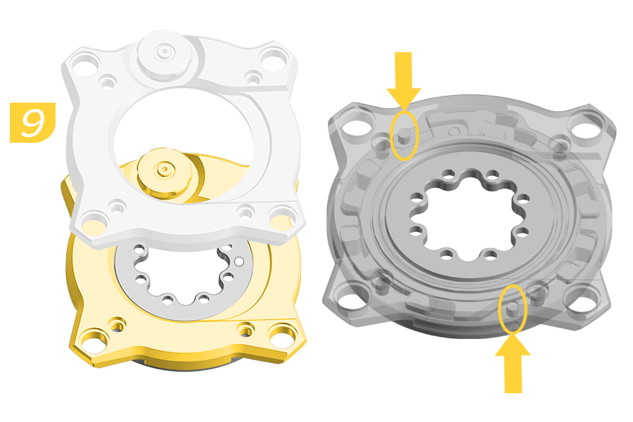
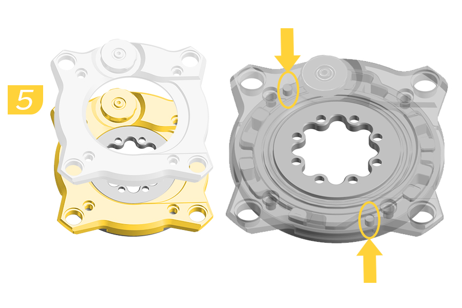
7. Install the cover onto the backplate.
Verify alignment of the backplate pins when installing the cover.
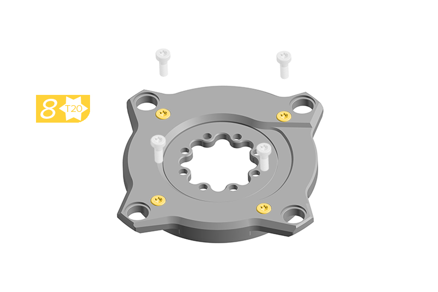
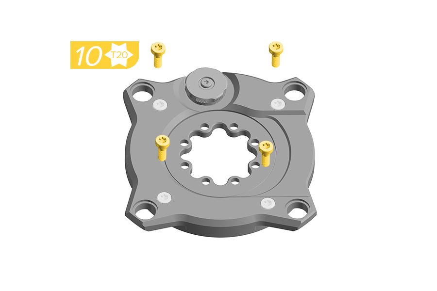
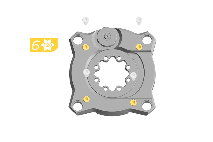
8. Install the four new screws through the cover until they engage with the backplate. Do not fully tighten.
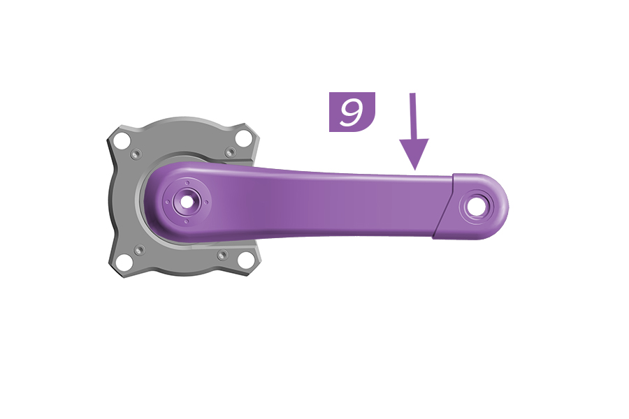
9. Firmly hold the Ochain spider and use the crank arm to push to the end of travel and release.
If the Ochain does not move freely, remove the crank arm and return to step 2.
If the Ochain does move freely, continue to step 10.
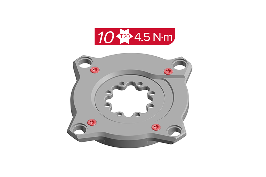
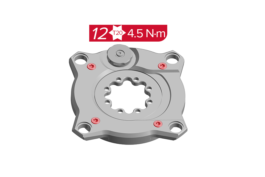
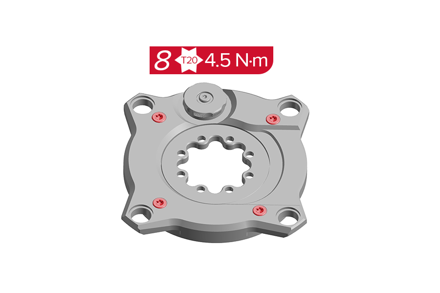
10. Tighten the four screws to the specified torque.
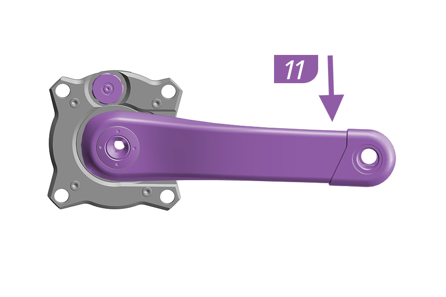
11. Install the Ochain onto the chainring. Install the crankarm as shown in the Ochain Spider Installation section and install the crank according to the manufacturer's instructions.
Inspect your Ochain spider for wear, looseness, or damage including cracks, dents, and serious scratches before each ride and after every fall or crash. Do not use your Ochain spider until it has been thoroughly inspected, repaired, or replaced.
After the first ride, retighten the chainring nuts to 9 N·m. Routinely check the chainring bolts for the correct torque values; never ride with loose bolts. Incorrect torque may cause malfunctioning or damage to your product.
Crash Hazard - Routinely check the chainring nuts to verify they are torqued to 9 N·m. Improper chainring nut torque can cause the chainring to loosen, which can cause the rider to crash resulting in serious injury and/or death.
It is recommended that you periodically clean your Ochain spider.
Use a damp cloth to wipe off any dirt and debris. Clean the components with soap and water only. Rinse thoroughly with water and allow the components to dry.
Avoid using a high pressure washer on the Ochain.
Your Ochain spider should be serviced at regular intervals to maximize performance.
Service Interval | Maintenance | Benefits |
|---|---|---|
Every 100 hours | Perform the Elastomer Replacement | Restore damping resistance. |
Every 200 hours or annually | Perform the Full Service | Restore original gliding, damping, and contamination durability. |
You must have the correct service kit before proceeding to the service steps. Consult the SRAM Spare Parts Catalog for kit information.
Part Number | Ochain Spider Model | Desired Degree | Service Kit | Included in Kit* |
|---|---|---|---|---|
11.6118.083.000 | Ochain R Ochain S Ochain N Ochain E | Adjustable - 0°, 3°, 6°, 9°, 12° | AM Ochain Full Service Kit (200 hour) | Gaskets, seals, springs, 8 balls, washer, m4 torx screws, elastomers 9 degree. |
11.6118.083.005 | Ochain R Ochain S Ochain N Ochain E | 6° 9° 12° | Ochain Elastomer Kit for R, S, N, E (100 hour) | 4 elastomers |
*Consult the Exploded Views section for more part information.
Ochain Model R is pictured in this section. Procedures are the same for Ochain Model N, S, and E unless otherwise described.
Remove the crankset from the bicycle and remove the Ochain spider from the crankset prior to performing service.

1. Remove the chainring from the Ochain spider by removing the four chainring bolts and nuts. Use a damp cloth to wipe off any dirt and debris from the Ochain spider.
2. Remove and clean the four screws. Set the screws aside.
3. Ochain R and S Only: The travel adjust knob must be in the 12° position for removal. All Gen B models: Carefully lift and remove the cover of the Ochain spider. Clean all surfaces with a clean cloth to remove dirt and old grease.
4. Remove and discard the four elastomers and end stroke token.
5. Apply lithium based grease to the end stroke area.
6. Install the new aluminum end stroke token into the END STROKE slot. Push the end stroke token fully clockwise, aligning the arrow on the end stroke with the arrow on the backplate.
7. Install a new green elastomer into each of the four ELASTOMER slots with the wider edge of the elastomer facing the outside edge of the backplate.
8. Apply lithium based grease around the internal seal and onto the rack.
9. Install the cover onto the backplate.
Verify alignment of the backplate pins when installing the cover.
10. Install the four screws through the cover until they engaged with the backplate. Do not fully tighten.
11. Firmly hold the Ochain spider and use the crank arm to push to the end of travel and release.
If the Ochain spider moves freely, remove the crank arm and continue to step 12.
If the Ochain does not move freely, remove the crank arm and return to step 3.
12. Tighten the four screws to the specified torque.
Clean the assembled Ochain spider with a clean towel to remove any excess grease.
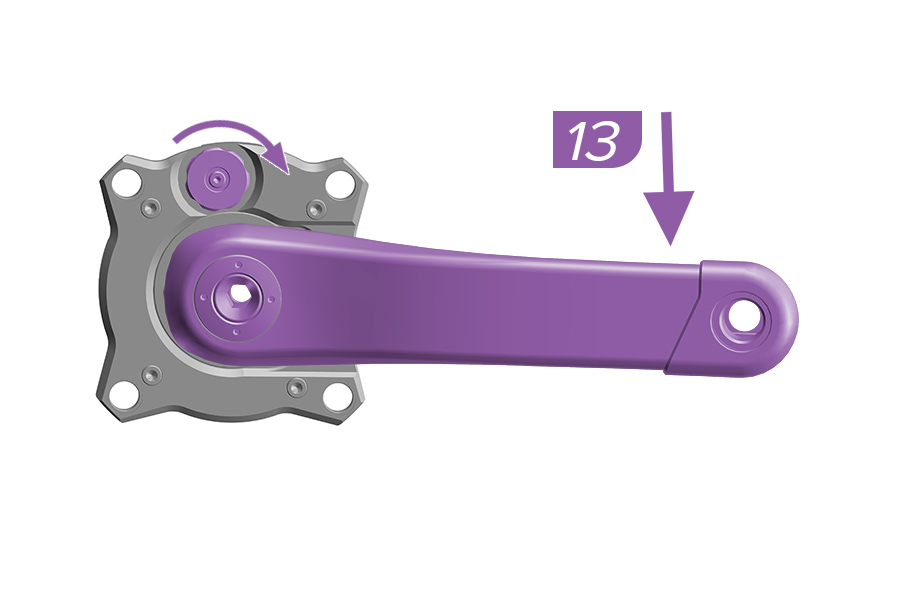
13. Firmly hold the Ochain and use the crank arm to test if the spider moves freely. Holding the crank down, test the adjustment knob by pulling the adjustment knob out and rotating it to the different settings.
If the Ochain spider moves freely and adjusts according to the knob setting, you have completed the service. Install the crank arm according to the manufacturer's instructions.
If the Ochain spider does not adjust according to the adjustment knob setting, remove the crank arm and return to step 2.
14. Install the Ochain to the chainring. Install the Ochain onto the crankarm as shown in the Ochain Spider Installation section.
.jpg)
Ochain Model R is pictured in this section. Procedures are the same for Ochain Model N, E, and S unless otherwise described.
Ochain R and S: Set the External Adjustment knob to 12° before removing the crankset.
Remove the crankset from the bicycle and remove the Ochain spider from the crankset prior to performing service.
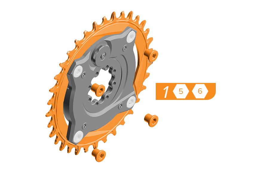
1. Remove the chainring from the Ochain spider by removing the four chainring bolts and nuts. Use a damp cloth to wipe off any dirt and debris from the Ochain spider.
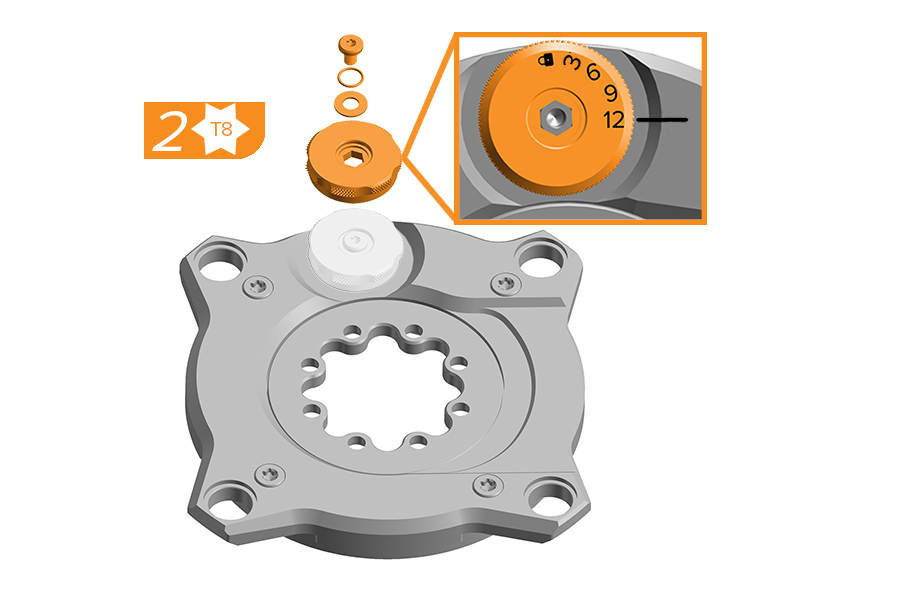
2. The External Travel Adjustment knob must be in the 12° position for removal. Place the Ochain spider race up on a flat surface. Remove the screw, washer, o-ring, and knob (12° position).
3. Remove and discard the four screws.
4. Carefully lift and remove the cover of the Ochain spider.
5a. Rotate the internal spider clockwise.
5b. Ochain R and S: Remove the spring, toothed shaft, rack, and rebound elastomer.
5b. Ochain N and E: Use an adjustable wrench to grip the flats and remove the travel chip.
6. Remove and discard the four elastomers, end stroke token, and rubber gasket.
7. Lift the internal spider from the backplate.
8. Remove and discard the external seal and internal spider ring from the internal spider.
9. Remove and discard the two wide bushings from the backplate.
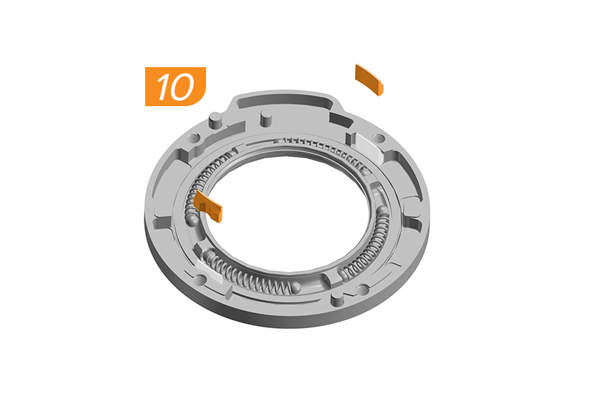
10. Remove and discard the two narrow bushings from the backplate.
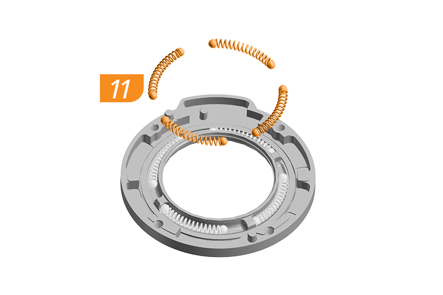
11. Remove and discard the eight steel balls and the four springs from the backplate.
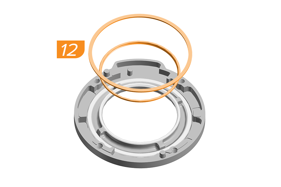
12. Remove and discard the internal spider ring and internal seal.
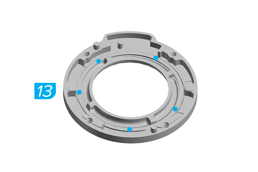
13. Apply 5 points of lithium based grease into the backplate.
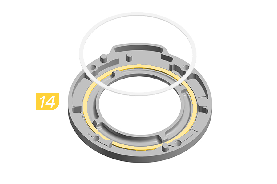
14. Install the new internal spider ring in the backplate.
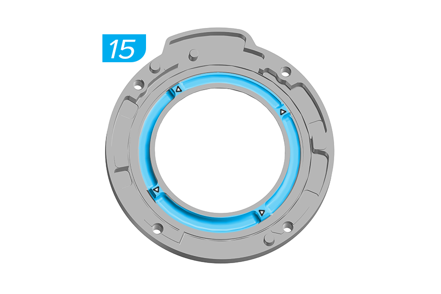
15. Apply lithium based grease into the spring grooves on the backplate.
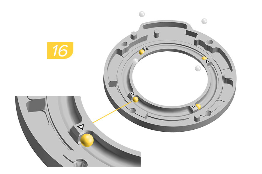
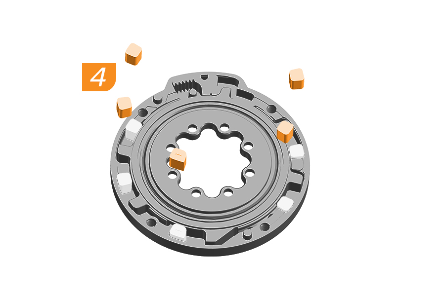
16. Install a new steel ball into each of the spring grooves aligning each ball with the white arrows on the edge of the groove.
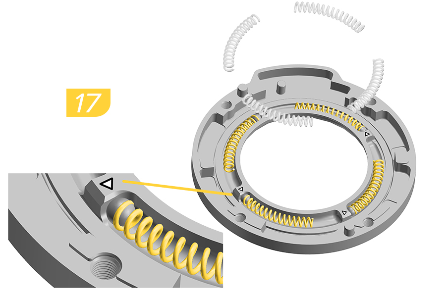
17. Install a new spring into each of the four spring grooves with the end of the spring flush against the steel ball.
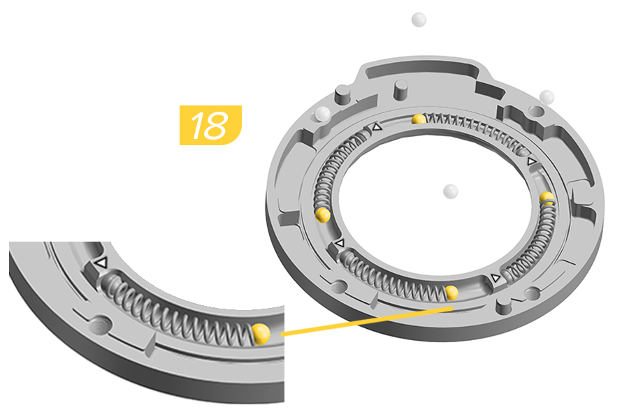
18. Install a new steel ball into each of the four spring grooves aligning each ball with the end of the spring.
Verify there is no space between the spring and the balls.
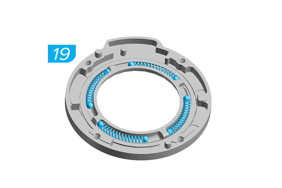
19. Apply a generous amount of lithium based grease to the top of the springs and steel balls.
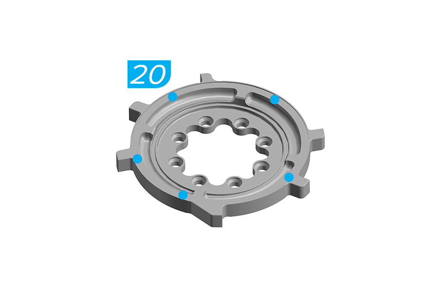
20. Apply five points of lithium based grease to the internal spider ring groove.
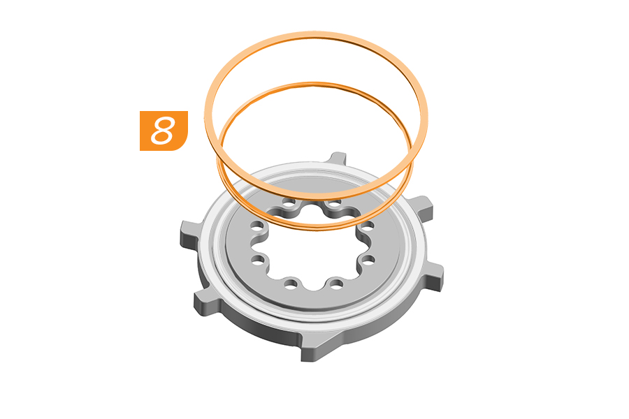
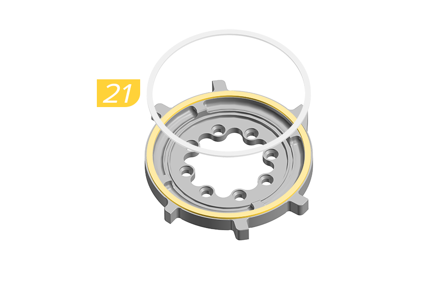
21. Install the new internal spider ring.
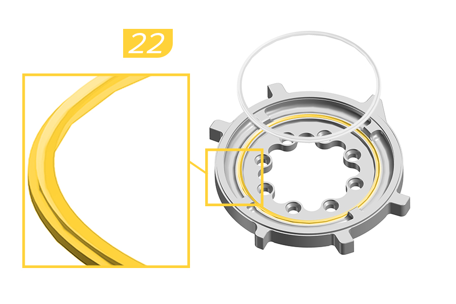
22. Install the new internal seal into the internal spider.
Verify the ring is fully installed with no parts folded or lifted up.
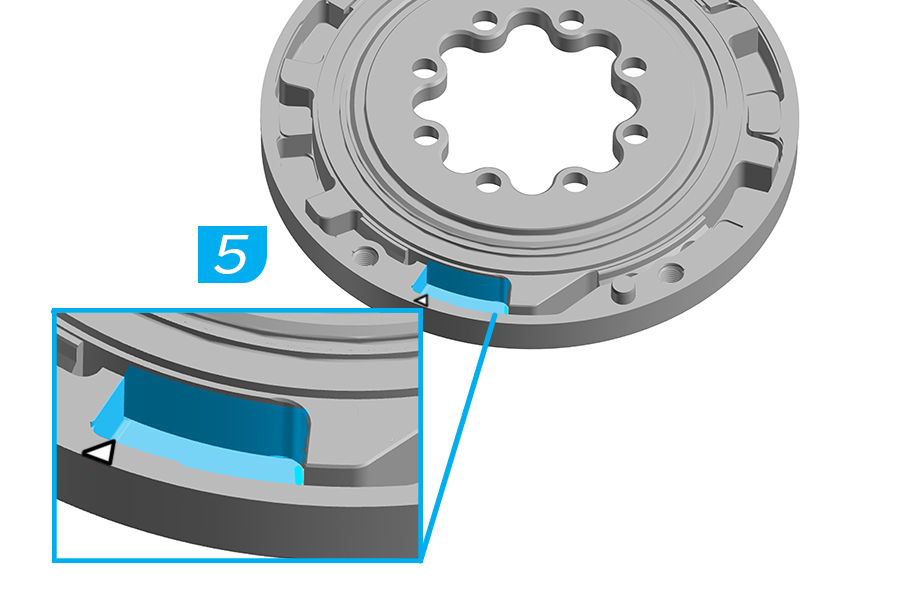
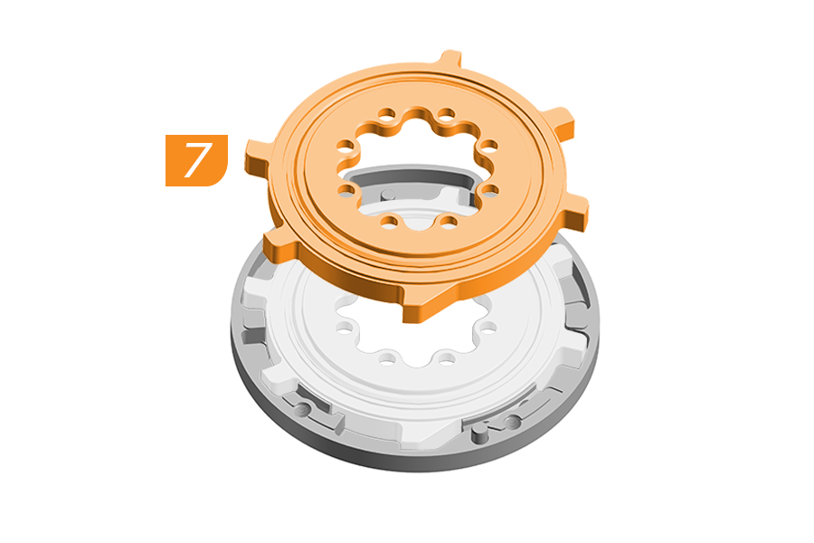
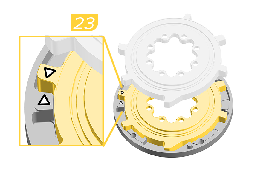
23. Carefully flip the internal spider over and install it into the backplate aligning the two white arrows. The two arrows must contact each other when installed.
Verify there is no space between the two arrows before continuing the service.
Slowly move the internal spider when rotating and installing it into the backplate. If any balls, springs, or rings fall out when flipping the internal spider, reinstall the pieces before proceeding.
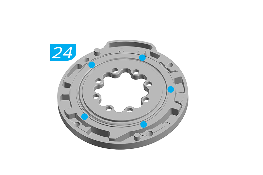
24. Apply five points of lithium based grease to the internal spider ring groove.
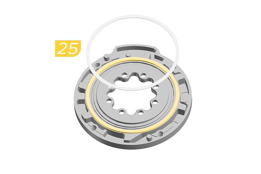
25. Install the internal spider ring.
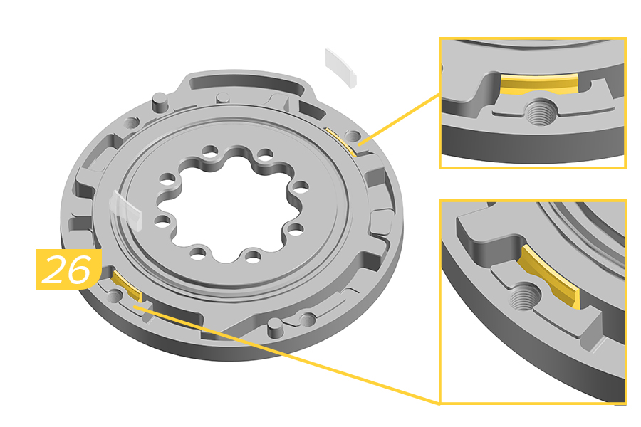
26. Install the two narrow bushings into the bushing slot with the chamfered edge of the bushing facing up.
27. Install the two wide bushings into the bushing slot with the chamfered edge of the bushing facing up.
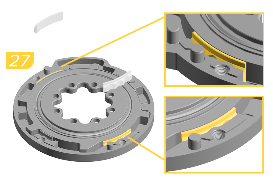
28. Apply lithium based grease in the left of the end stroke area.
29a. Install the new yellow rack elastomer into the rack.
Rack and Elastomer are keyed for one orientation.
29b. Add grease on the top surface of the rack.
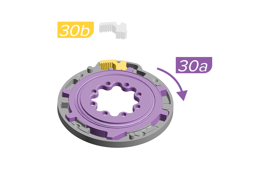
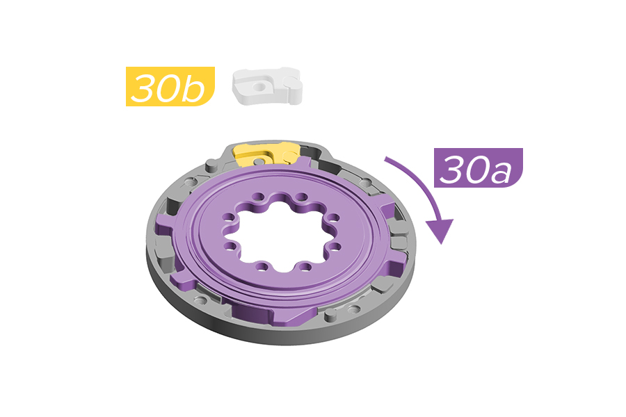
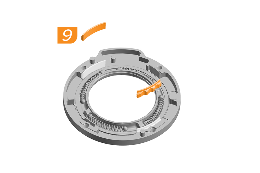
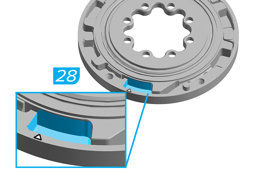
30a. Using your fingers or the crankarm, rotate the internal spider clockwise .
30b. Ochain R and S: Install the rack and elastomer into the backplate.
Verify the rack is installed correctly and the yellow elastomer is pressed against the YELLOW mark on the internal spider.
30b. Ochain N and E: Install the travel chip with the desired degree of rotation.
Verify the travel chip is installed correctly and the yellow elastomer is pressed against the YELLOW mark on the internal spider.
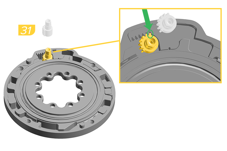
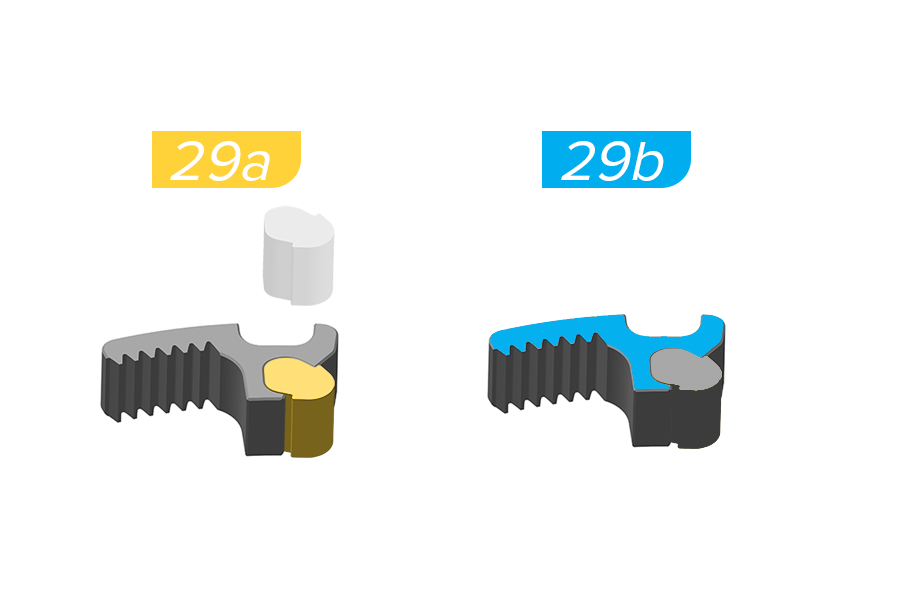
31. Install the toothed shaft onto the pin on the backplate.
Verify that the last tooth of the shaft is aligned with the last tooth of the rack.
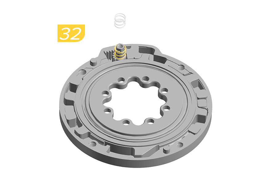
32. Install the spring onto the pin of the toothed shaft.
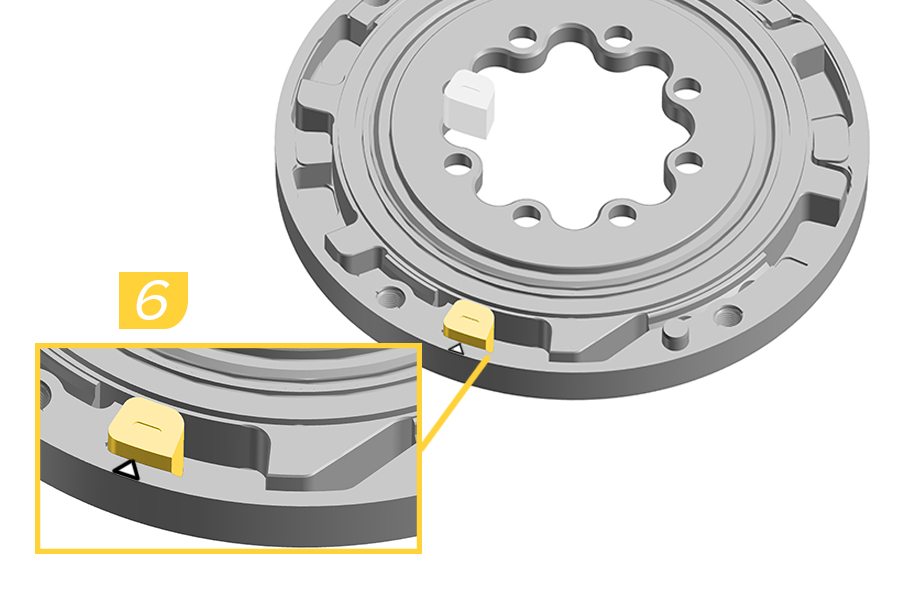
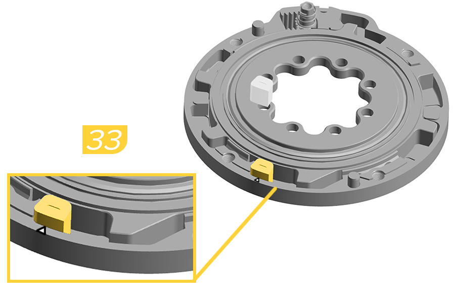
33. Install the end stroke token into the END STROKE slot. Push the end stroke token fully clockwise, aligning the arrow on the end stroke with the arrow on the backplate.
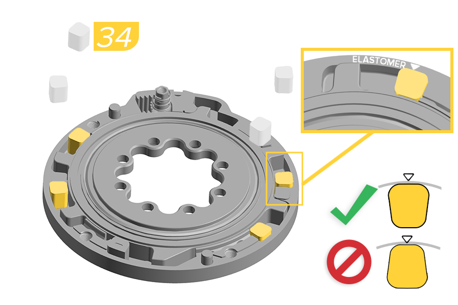
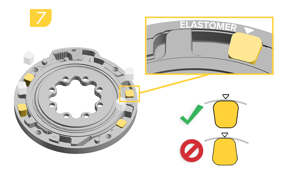
34. Install a new green elastomer into each of the four ELASTOMER slots with the wider edge of the elastomer facing the outside edge of the backplate.
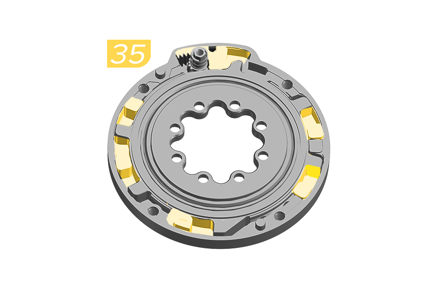
35. Apply a total of 0.6ml Maxima Plush Dynamic Lube Heavy, distributed between the four elastomer pockets, on top of the end stroke pocket, and on top of the rack.
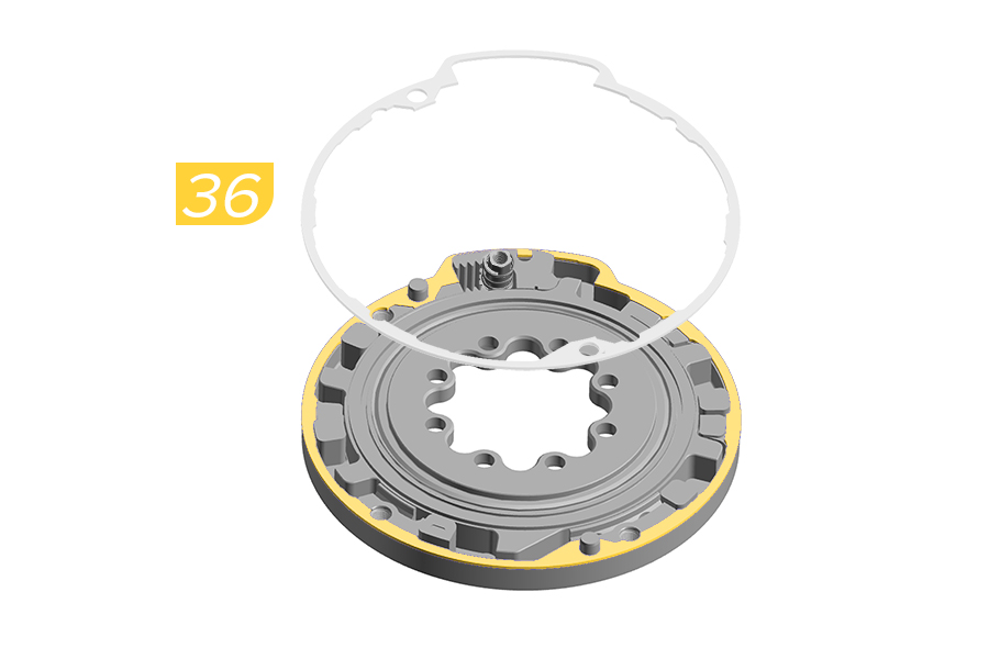
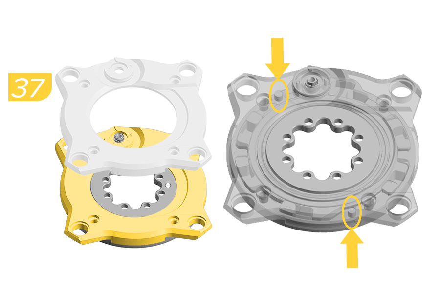
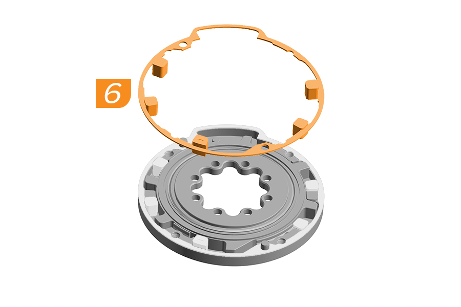
36. Carefully install the new rubber gasket on the top edge of the backplate.
37. Install the cover onto the backplate.
Verify alignment of the backplate pins when installing the cover.
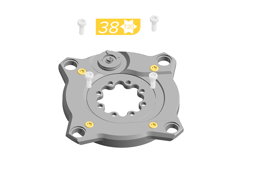
38. Install the four new screws through the cover until they are engaged into the backplate. Do not fully tighten.
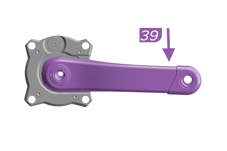
39. Firmly hold the Ochain spider and use the crank arm to push to the end of travel and release.
If the Ochain spider moves freely, remove the crank arm and continue to step 40.
If the Ochain does not move freely, remove the crank arm and return to step 3.
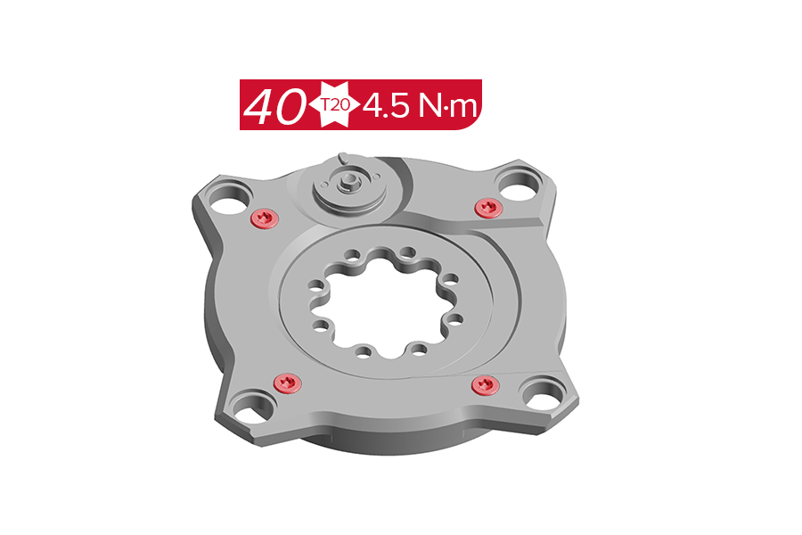
40. Tighten the four screws to the specified torque.
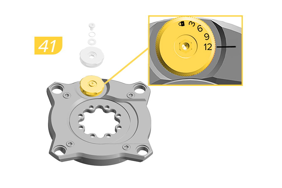
41. Install the External Adjustment knob (set to 12° position), o-ring, washer, and screw on Ochain cover.
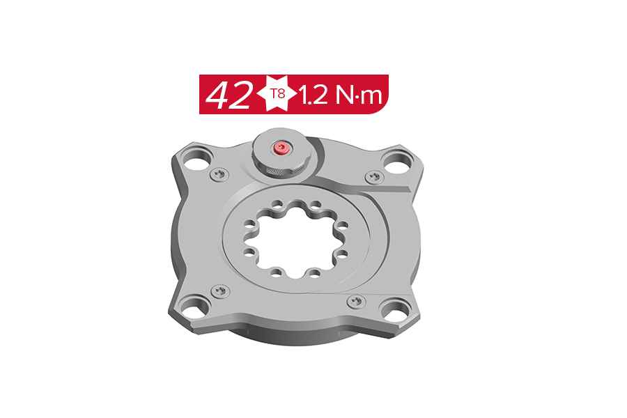
42. Tighten the screw to the specified torque.
Clean the assembled Ochain spider with a clean towel to remove any excess grease.
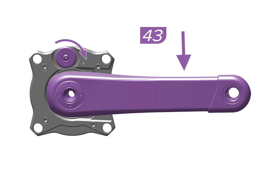
43. Firmly hold the Ochain and use the crank arm to push to the end of travel and release. Holding the crank down, test the adjustment knob by pulling the adjustment knob out and rotating it to the different settings.
If the Ochain spider moves freely and adjusts according to the knob setting, you have completed the Ochain spider full service. Install the crank arm as shown in the Ochain Spider Installation section and install the crank according to the manufacturer's instructions.
If the Ochain spider does not adjust according to the adjustment knob setting, remove the crank arm and return to step 41.
Part Number | Upgrade Kit | Contains |
|---|---|---|
11.6118.083.003 | Ochain Upgrade Kit N to R | External Travel Adjust knob, Rack, steel insert, spring, washer, bolts and outboard plate. |
11.6118.083.004 | Ochain Upgrade Kit E to S | External Travel Adjust knob, Rack, steel insert, spring, washer, bolts and outboard plate. |
Ochain Model N is pictured in this section. Procedures are the same for Ochain Model E unless otherwise described.
Remove the crankset from the bicycle and remove the Ochain spider from the crankset prior to performing service.
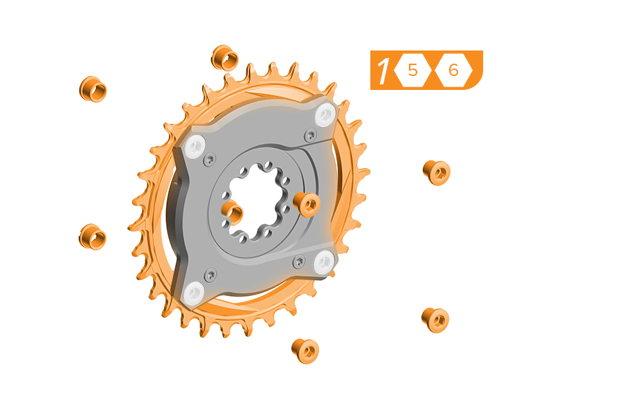
1. Remove the chainring from the Ochain spider by removing the four chainring bolts and nuts. Use a damp cloth to wipe off any dirt and debris from the Ochain spider.
2. Place the Ochain spider face up on a flat, stable working surface. Remove and clean the four screws.

3a. Use the crank arm to rotate the internal spider.
3b. Use pliers to remove the travel chip from the backplate while pushing down on the internal spider with hand or crankarm to keep in place.
4a. Use the crank arm to rotate the internal spider.
4b. Install the rack into place into the backplate. Push the rack down fully into position in the backplate.
5. Install the cover onto the backplate.
Verify alignment of the backplate pins when installing the cover.
6. Install the four new screws through the cover until they are engaged into the backplate. Do not fully tighten.
7. Firmly hold the Ochain spider and use the crank arm to push to the end of travel and release.
If the Ochain spider moves freely and knob is functioning properly when set, the upgrade is complete.
If the Ochain does not move freely, remove the crank arm and return to step 3.
8. Tighten the four screws to the specified torque.
9. Install the Ochain onto the crankarm as shown in the Ochain Spider Installation section and install the crank according to the manufacturer's instructions.
This concludes service instructions for Ochain Gen B.
♻For recycling and environmental compliance information, please visit www.sram.com/en/company/about/environmental-policy-and-recycling