General Safety

Safety First!
We care about YOU. Please, always wear your safety glasses and protective gloves when servicing SRAM products. Protect yourself! Wear your safety gear!


Safety First!
We care about YOU. Please, always wear your safety glasses and protective gloves when servicing SRAM products. Protect yourself! Wear your safety gear!
Always wear safety glasses and nitrile gloves when working with brake fluid.
Place an oil pan on the floor underneath the area where you will be working on the brake.
Use only SRAM Hydraulic Brake grease.
If the brake system has been contaminated with DOT fluid, the entire brake system including the lever and the caliper must be replaced. DOT brake fluid contamination will cause degradation of the seals used in the mineral oil system and the brakes will be unsafe to continue to use.
Used mineral brake oil must be recycled or disposed of in accordance to local, state, and federal regulations. Never pour used brake oil or fluid down a sewage or drainage system or into the ground or body of water.
CRASH HAZARD
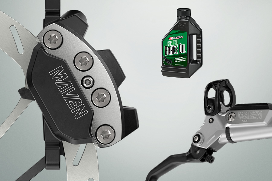
Do not use DOT 4 or DOT 5.1 brake fluids. Use only Maxima Mineral brake oil with SRAM Mineral oil hydraulic brakes. Do not use any other oil or fluid; it will damage the system and make the brakes unsafe to use, which could lead to serious injury and/or death.
Do not allow any brake fluid to come in contact with the brake pads. If this occurs, the pads are contaminated and must be replaced.
Servicing your brakes removes all of the brake fluid from the system. You must bleed the brakes after you service the brake caliper and/or lever.
For brake bleed and brake hose shortening instructions, visit sram.com/service.
We recommend that you have your SRAM Brake components serviced by a qualified bicycle mechanic. Servicing SRAM components requires knowledge of bicycle mechanics as well as the special tools and lubricants/fluids used for service. SRAM brake systems need to be serviced periodically to optimize braking function. If brake fluid is leaking from any area of the brake there may be damage or wear and tear to the internal moving parts. If the system has been contaminated with the wrong fluid there may be damage to all rubber and plastic internal parts. If your brake was damaged in a crash there may be damage to the lever blade, pushrod, and housing assemblies. Inspect and replace these parts to restore proper brake function.
Visit sram.com/service for the latest SRAM Spare Parts catalog and technical information. For order information, please contact your local SRAM distributor or dealer.
Information contained in this publication is subject to change at any time without prior notice. Your product's appearance may differ from the pictures contained in this publication.
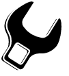
Click on the icon at the top right corner of the screen to display the complete list of tools and supplies for this manual in a scrollable dropdown list.
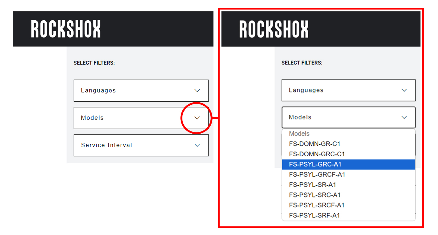
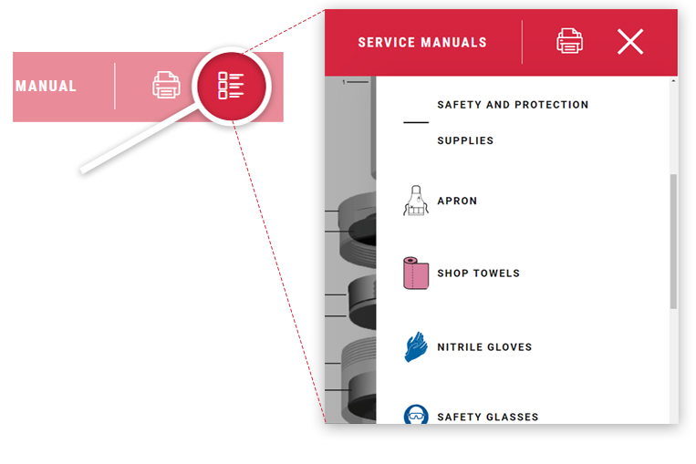
Use the dropdown lists in the SELECT FILTERS: window at the top left of the page to select the preferred language, product model code, and instructional content. Product instructional content filters will vary.
Language Filter: Select Language first. When a new language is selected, all other selected filters will reset.
All non-Language Filters: To reset a non-language filter, click on the X.
Product model code and specification details can be identified with the serial number on the product. Model codes can be used to identify the product type, series name, model name, and product version associated with the production model year. Product details can be used to identify spare parts, service kit, and lubricant compatibility.
Model Code example: DB - MVN - ULT - A1
DB = Product Type - Disc Brake
MVN = Platform/Series - Maven
ULT = Model - Ultimate
A1 = Version - (A - first generation, 1 - first iteration)
To identify the model code, locate the serial number on the product and enter it into the Search by Model Name or Serial Number field at www.sram.com/service.
Your product's appearance may vary from those pictured in this manual.
Images and examples pictured are for conceptual purposes and may vary from product design, appearance, and performance.
Consult sram.com/service whenever a separate manual is referenced in this document.
Read the full warranty policy for your components at sram.com/en/service/warranty.
For information about trademarks used in this manual, visit sram.com/website-terms-of-use.
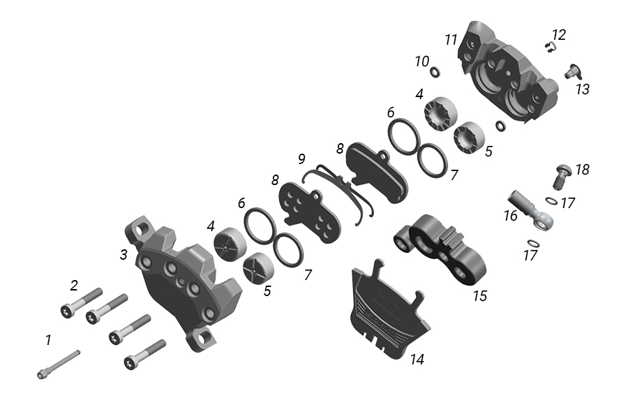
1. Pad Retention Bolt | 6. B1: Piston Seal 18 mm (2)* | 13. Bleed Port Plug |
2. Caliper Body Bolt (4) | 7. Piston Seal 18 mm (2)* | 14. Pad Spacer |
3. Outboard Caliper Body | 8. Brake Pad (2) | 15. Bleed Block (X-Large) |
4. A1: Caliper Piston 19.5 mm (2)* | 9. Pad H-Spring | 16. Banjo |
4. B1: Caliper Piston 18 mm (2)* | 10. Caliper Body Seal (2) | 17. Banjo Bolt O-Ring (2) |
5. Caliper Piston 18 mm (2)* | 11. Inboard Caliper Body | 18. Banjo Bolt |
6. A1: Piston Seal 19.5 mm (2)* | 12. E-Clip |
* Ultimate and Silver B1 brakes have four 18 mm pistons and four 18 mm piston seals.
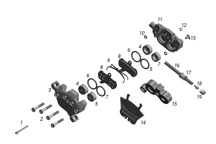
1. Pad Retention Bolt | 6. B1: Piston Seal 18 mm (2)* | 13. Bleed Port Plug |
2. Caliper Body Bolt (4) | 7. Piston Seal 18 mm (2)* | 14. Pad Spacer |
3. Outboard Caliper Body | 8. Brake Pad (2) | 15. Bleed Block (X-Large) |
4. A1: Caliper Piston 19.5 mm (2)* | 9. Pad H-Spring | 16. Hose |
4. B1: Caliper Piston 18 mm (2)* | 10. Caliper Body Seal (2) | 17. Compression Nut |
5. Caliper Piston 18 mm (2)* | 11. Inboard Caliper Body | 18. Hose Barb |
6. A1: Piston Seal 19.5 mm (2)* | 12. E-Clip | 19. Compression Fitting |
* Bronze B1 brakes have four 18 mm pistons and four 18 mm piston seals.
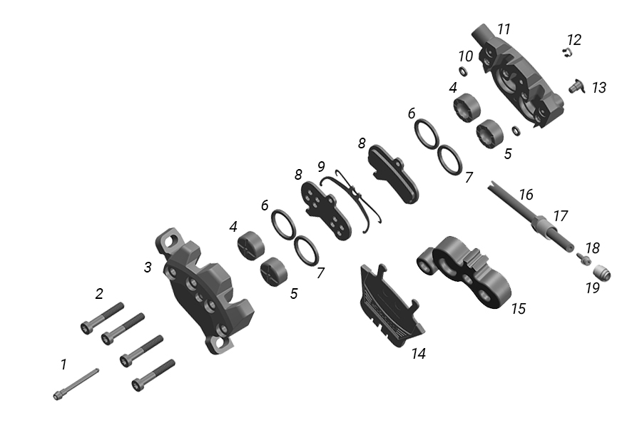
1. Pad Retention Bolt | 8. Brake Pad (2) | 15. Bleed Block (X-Large) |
2. Caliper Body Bolt (4) | 9. Pad H-Spring | 16. Hose |
3. Outboard Caliper Body | 10. Caliper Body Seal (2) | 17. Compression Nut |
4. Caliper Piston 18 mm (2) | 11. Inboard Caliper Body | 18. Hose Barb |
5. Caliper Piston 18 mm (2) | 12. E-Clip | 19. Compression Fitting |
6. Piston Seal 18 mm (2) | 13. Bleed Port Plug | |
7. Piston Seal 18 mm (2) | 14. Pad Spacer |
CRASH HAZARD
If the brake system has been contaminated with DOT fluid, the entire brake system including the lever and the caliper must be replaced. DOT brake fluid contamination will cause degradation of the seals used in the mineral oil system and the brakes will be unsafe to continue to use.
Caliper service is only required if the pistons are damaged.
If the calipers are operating normally, they do not require disassembly and service. Clean the calipers and install the brake pads.
The brake caliper must be serviced before the brake lever. The lever must be connected to the caliper and the brakes must still have fluid in them in order to advance the pistons and service the caliper. Once the lever has been disconnected and the fluid is drained it is not possible to advance the pistons.
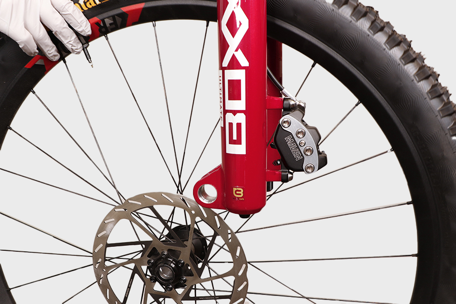
Clamp the bicycle into a bicycle work stand and remove the wheel.
Remove the caliper bolts and lever clamp bolt.

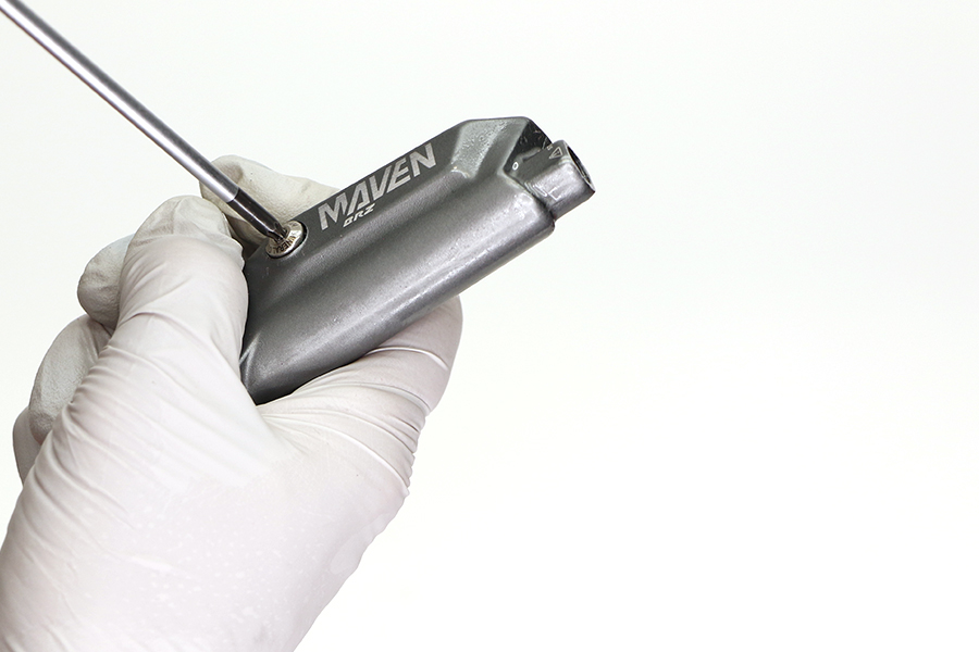
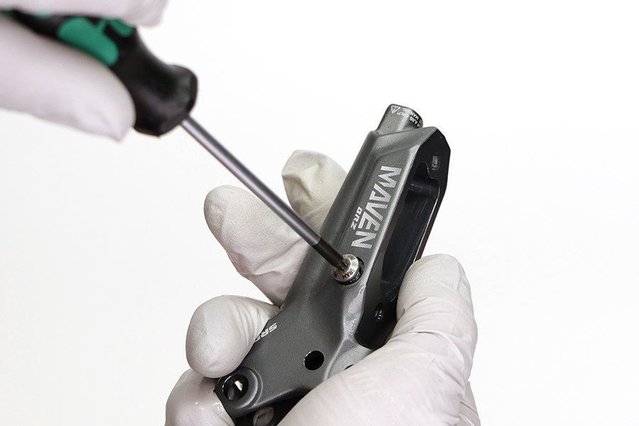
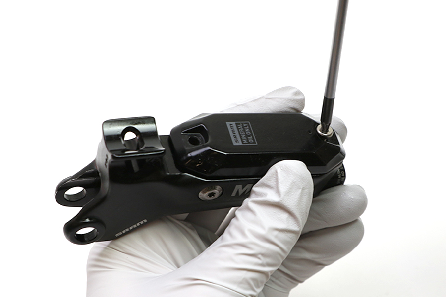
Remove the E-clip from the pad retention bolt.

Remove the pad retention bolt from the caliper.
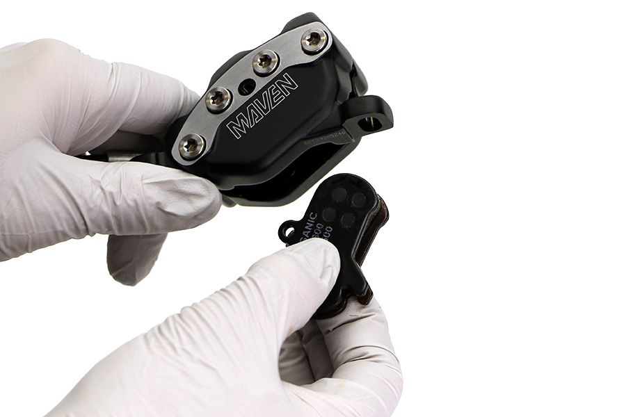
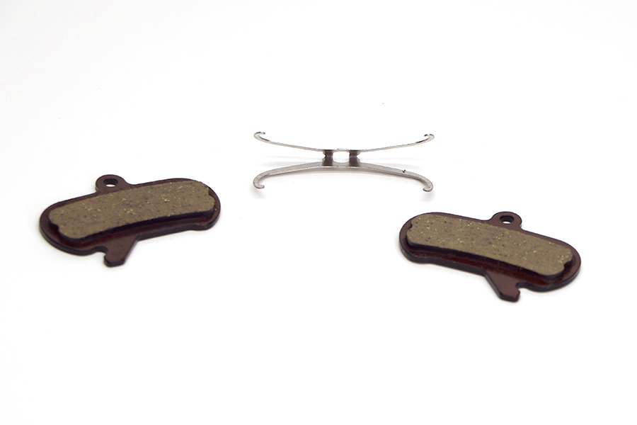
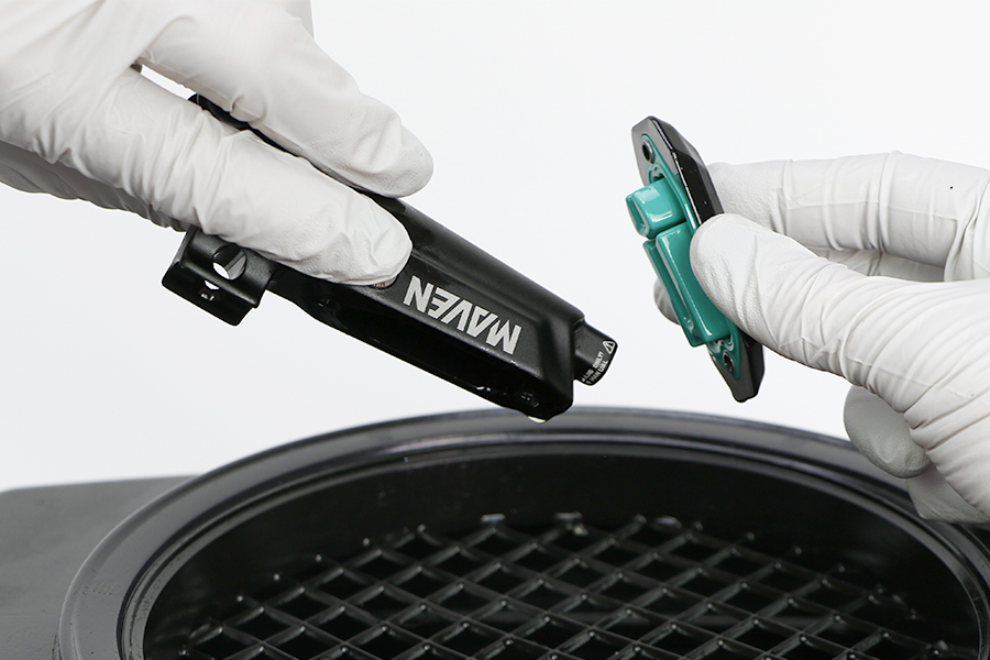
Remove the brake pads and pad H-spring from the caliper.
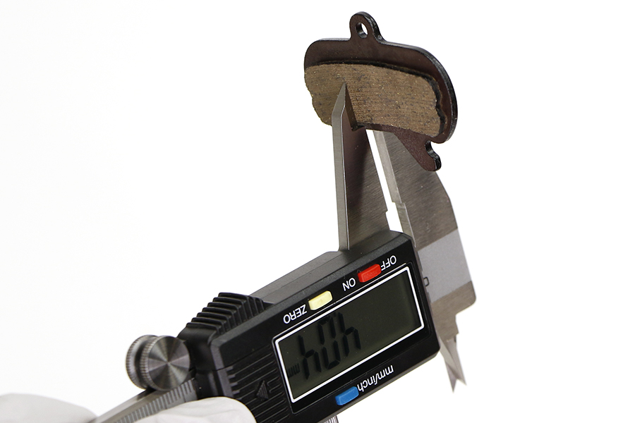
If the brake pad thickness is less than 3 mm then replace the pads.
The brake caliper must be serviced before the brake lever. The lever must be connected to the caliper and the brakes must still have fluid in them in order to advance the pistons and service the caliper. Once the lever has been disconnected and the fluid is drained it is not possible to advance the pistons.
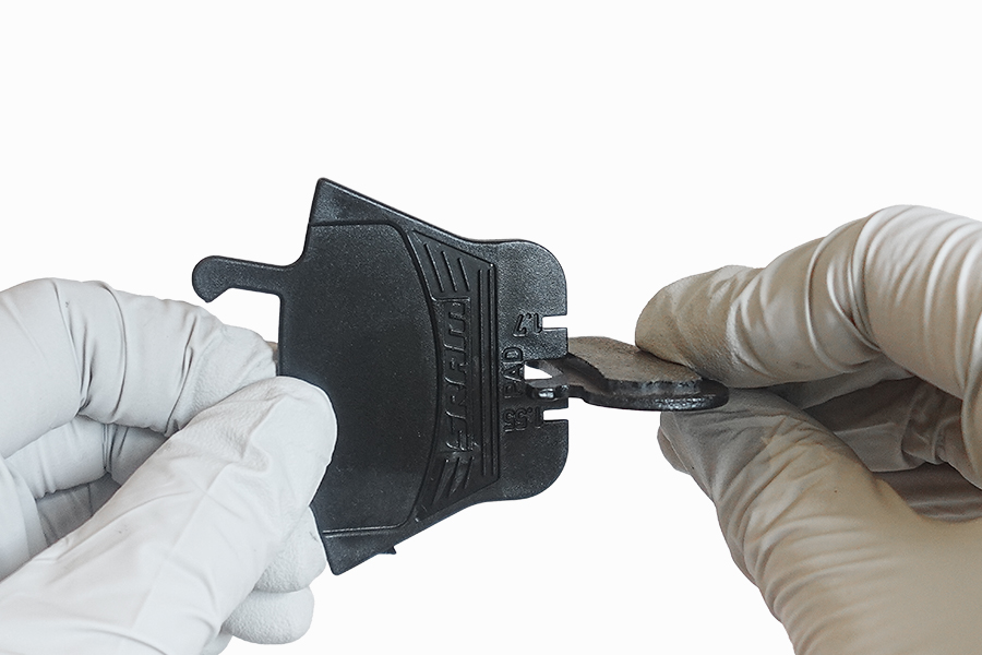
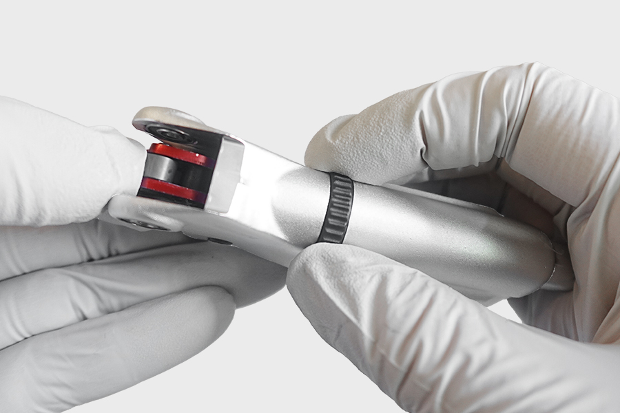
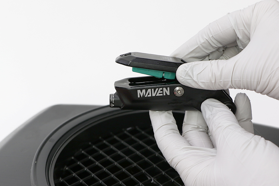
Insert the pad spacer so that it snaps into place.


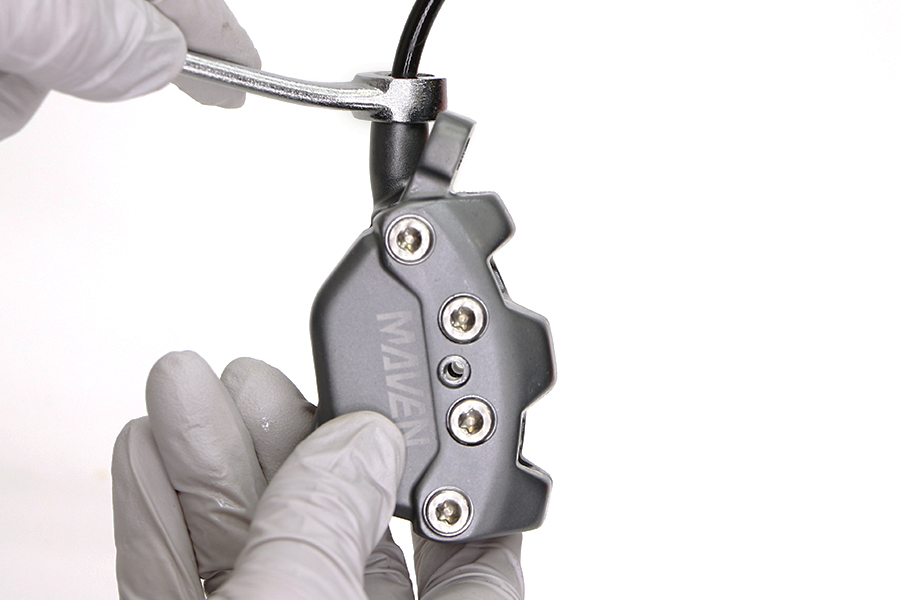
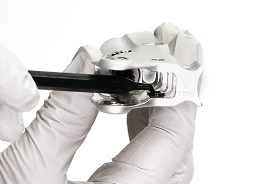
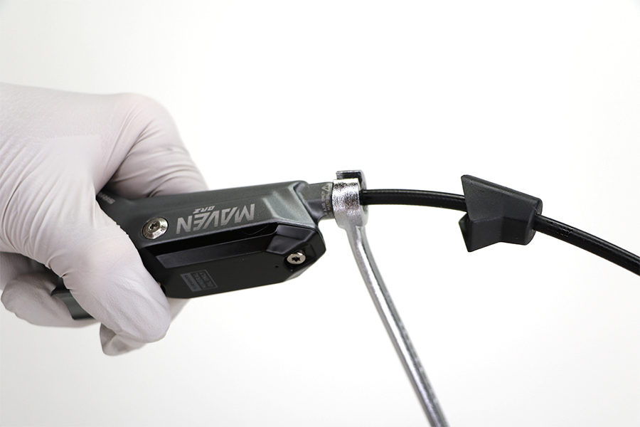
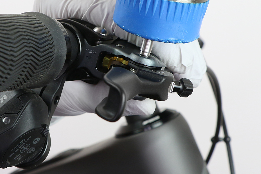
Squeeze the brake lever to advance the pistons until they contact the pad spacer. Make sure the pistons are advancing evenly. You may need to use a tire lever to hold back any pistons that advance more than other pistons; this will allow the other pistons to advance.
Remove the pad spacer.

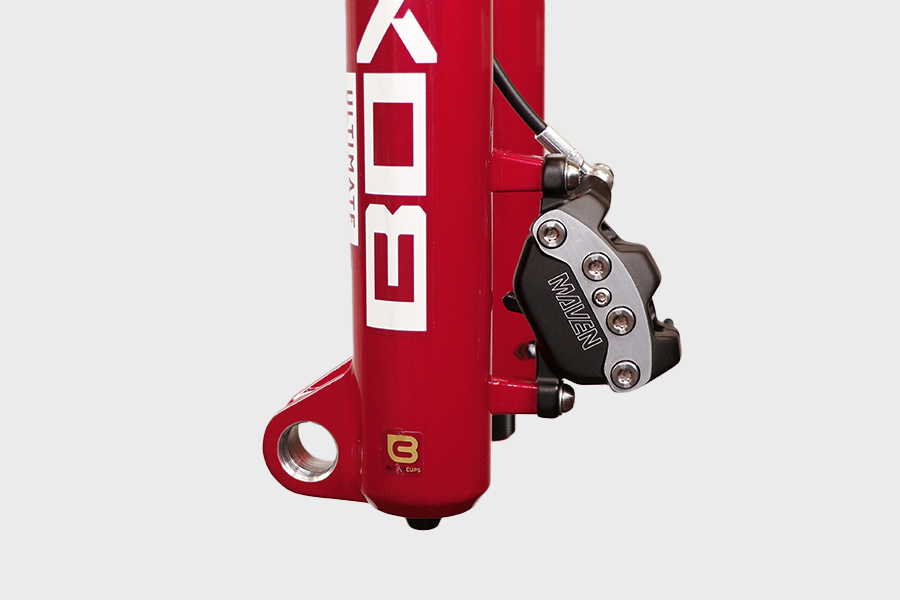
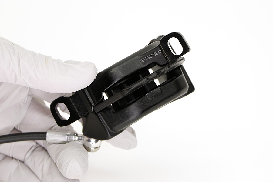
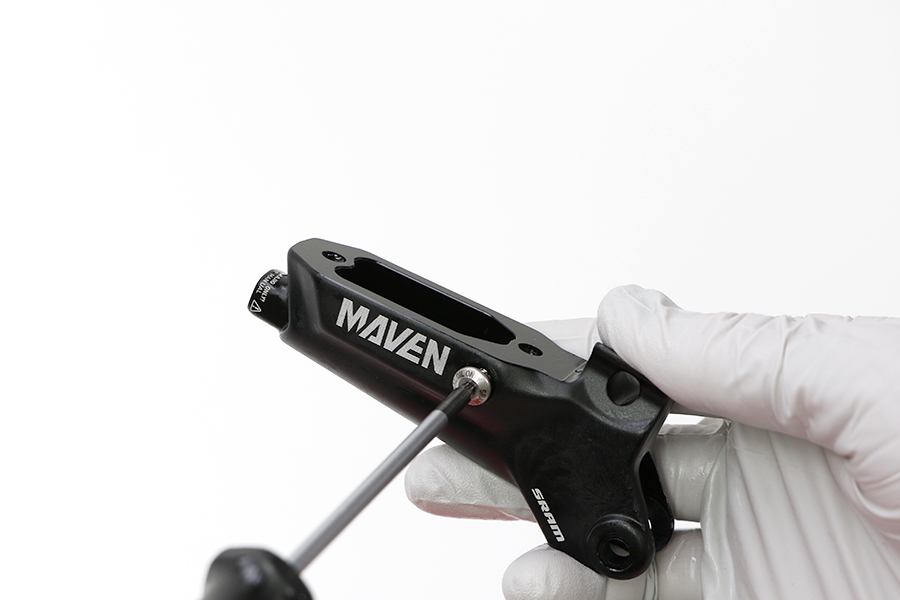
Ultimate and Silver: Remove the banjo bolt and hose.
Bronze and Base: Remove the compression nut and hose.


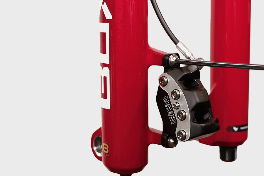
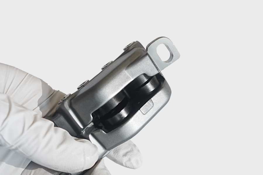
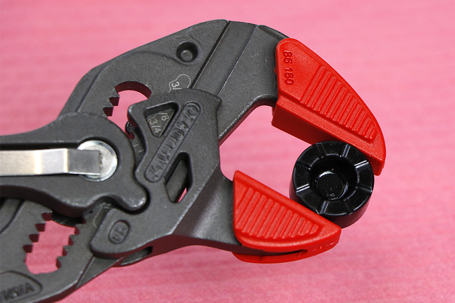
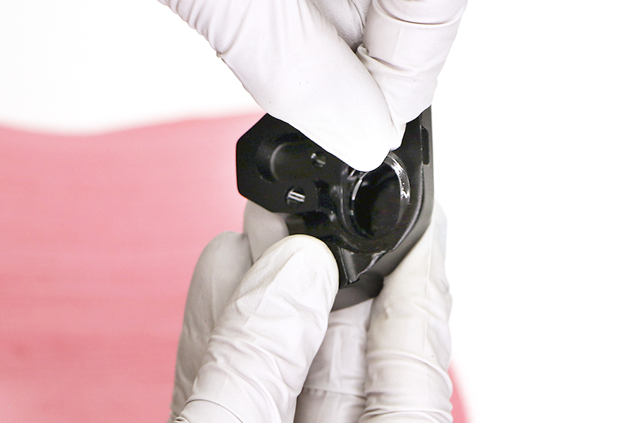
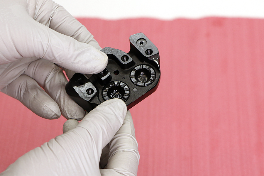
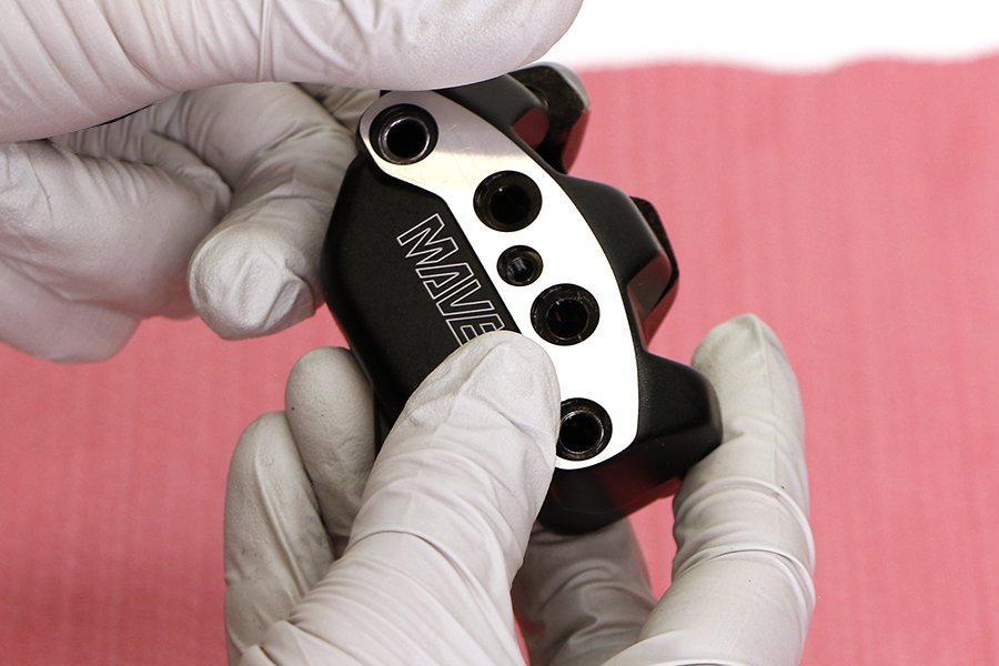
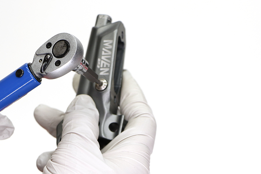
Loosen the four caliper body bolts. Remove the caliper body bolts and set aside.

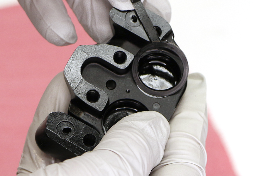
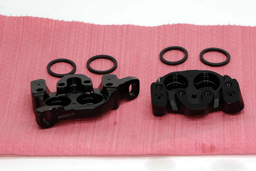
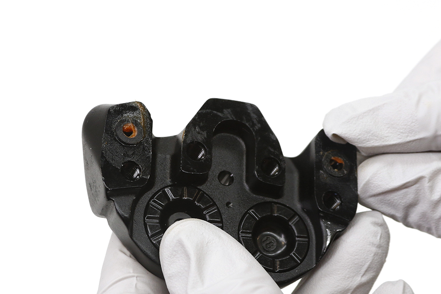
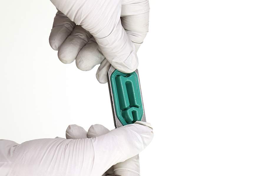
Separate the caliper body halves.
Use your fingers or a tool to remove the pistons from each caliper body half.

Use a cable tie or plastic pick to remove the piston seals from the four piston bores.
CRASH HAZARD
Use a cable tie or plastic pick. Do not scratch the seal gland. Scratches could cause fluid to leak when the brake is applied, which will contaminate the brake pads. Oil on brake pads could lead to a brake failure which may result in serious injury or death.
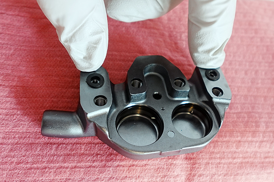
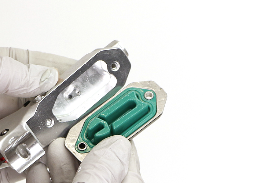
Remove the caliper body seals.
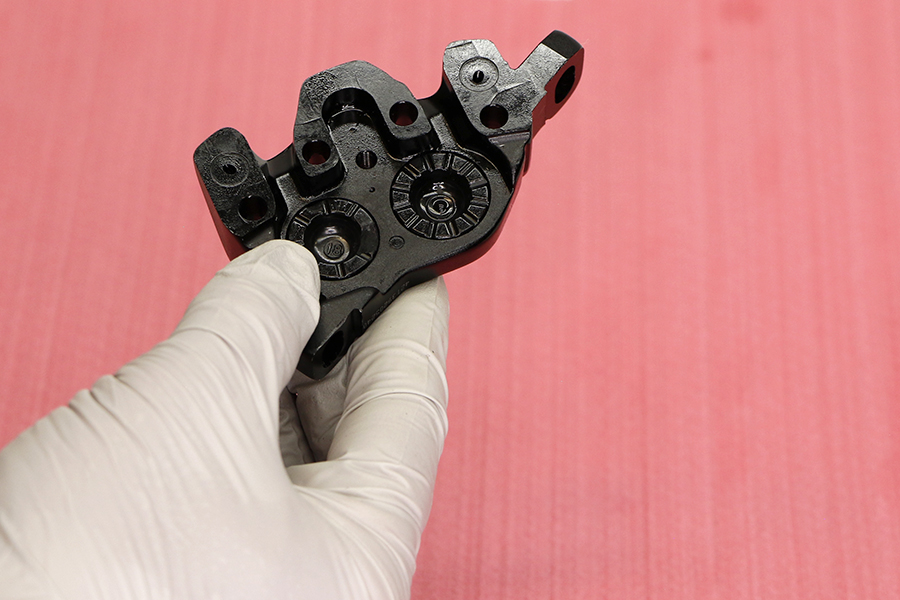
Clean the caliper body halves and piston bores.
Apply Maxima Mineral Brake oil to the new caliper seals and install into each caliper piston bore according to their diameter.
Do not apply grease to the caliper piston seals. Grease on the seals will reduce the clearance between the pads and rotors when the brake is released resulting in low pad rollback.
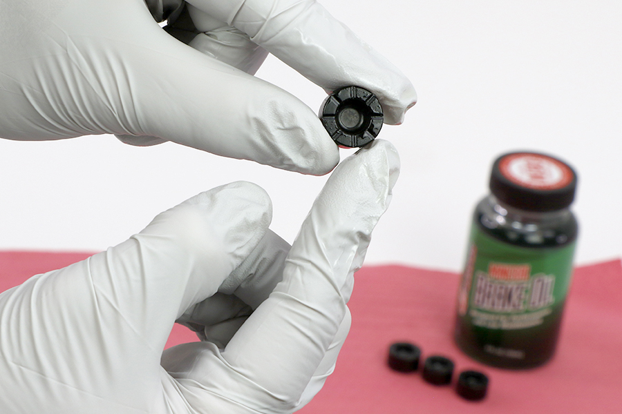
Inspect the caliper pistons for damage and replace the pistons if damaged. Apply a small amount of Maxima Mineral Brake oil to the circumference of each piston.
Install the pistons into each half of the caliper body according to their diameter.
Use only Maxima Mineral Brake oil. Do not apply grease to the caliper piston seals or pistons. Grease on the seals or piston will reduce the clearance between the pads and rotors when the brake is released resulting in low pad rollback.
Spray isopropyl alcohol on the caliper halves and both of your gloves, and clean them with a shop towel.
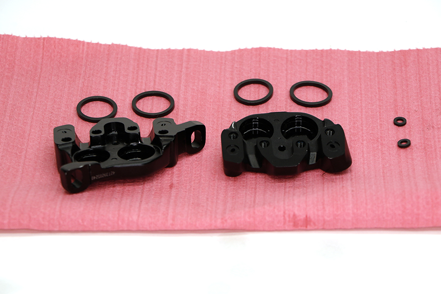
Apply a small amount of SRAM Hydraulic Brake grease to the new caliper body seals and install them onto the outboard caliper half.

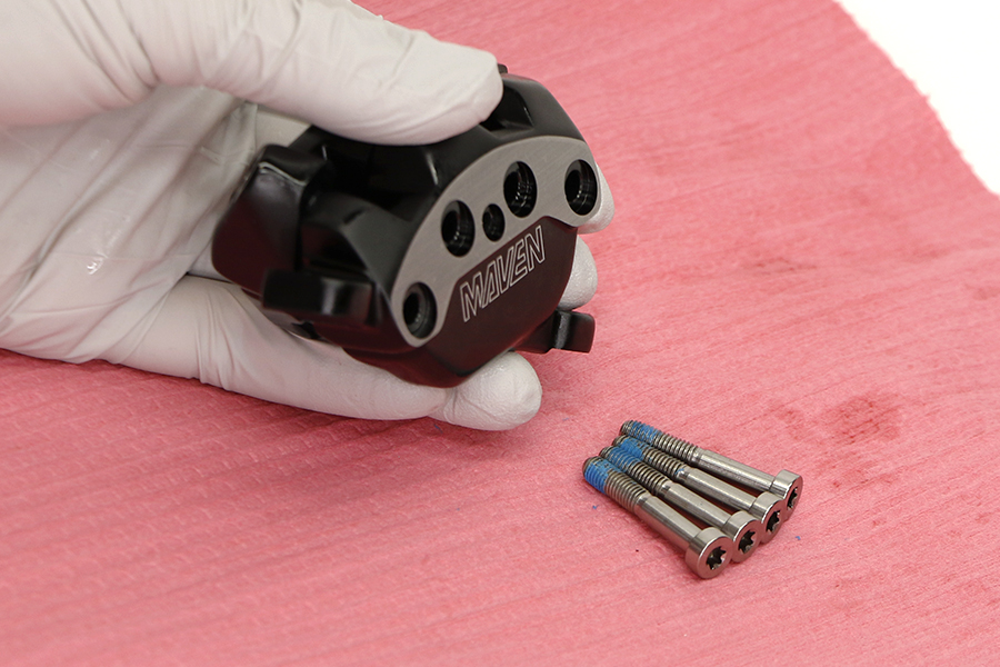
Align the caliper body halves and thread each body bolt into the caliper.
New body bolts come with Loctite Blue 242 applied. If you re-use the body bolts, then you must apply new Loctite Blue 242 or equivalent to the bottom 5 mm of the body bolt threads. Failure to apply Loctite or equivalent could result in the bolts coming loose and cause a crash.

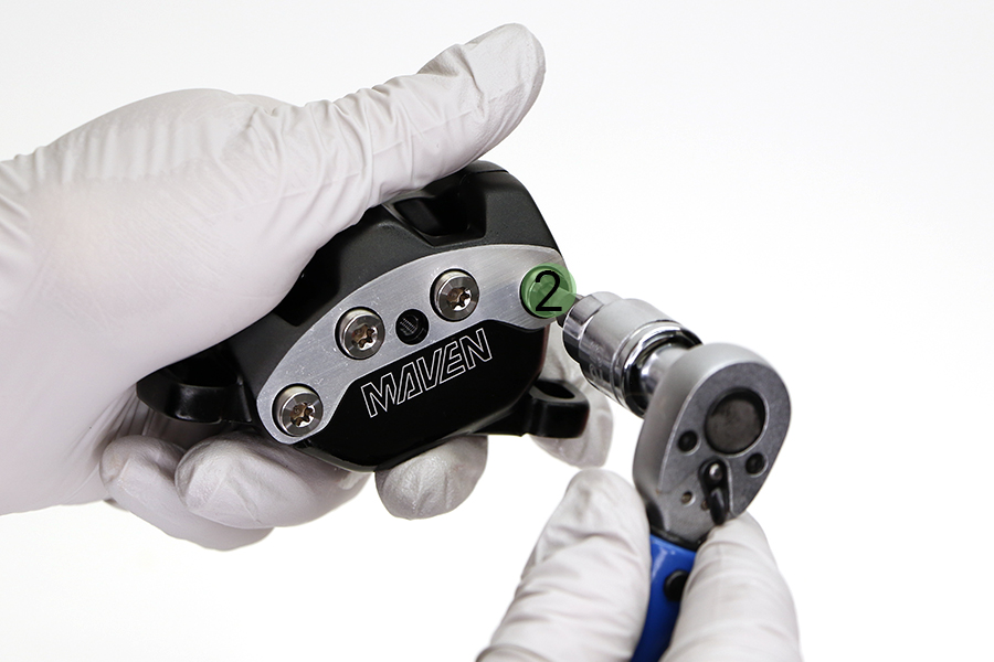


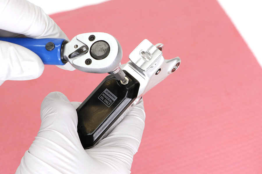
Tighten the bolts in an alternating pattern starting with the outside bolts and then the inside bolts until torque is achieved.


Install the pad retention bolt.
Insert the bleed block into the caliper.
You must bleed your brakes before reinstalling the brake pads.
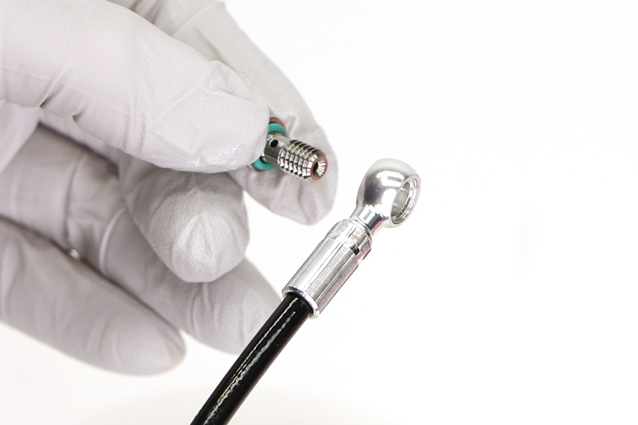
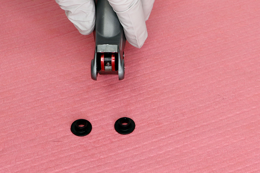
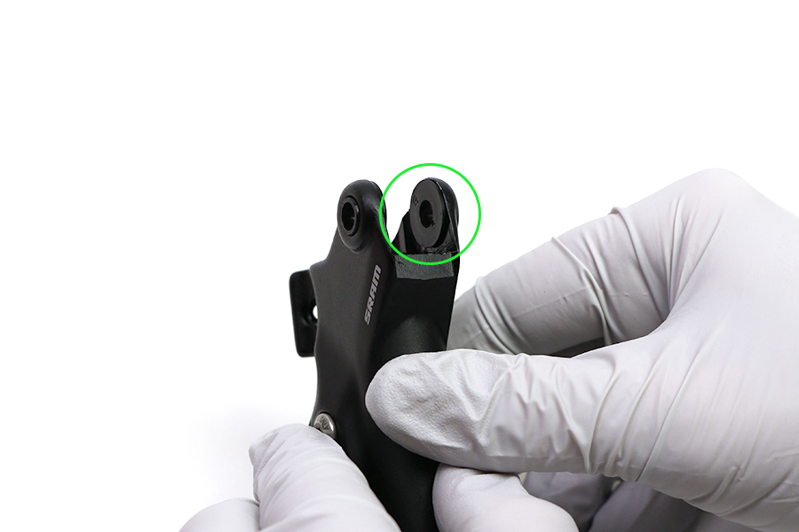
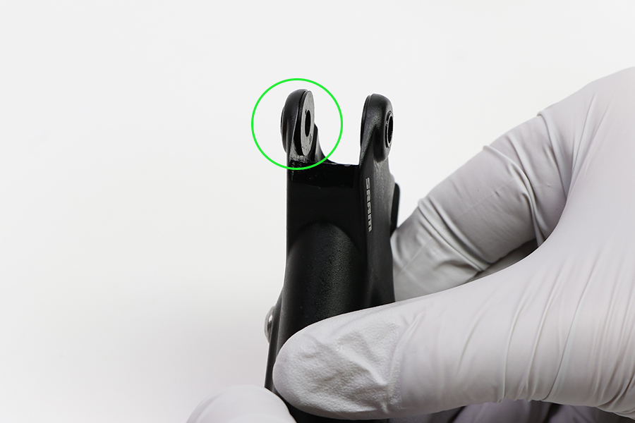
Remove the banjo bolt o-rings from the bolt.
Apply SRAM Hydraulic Brake grease to the new o-rings and install onto the banjo bolt.
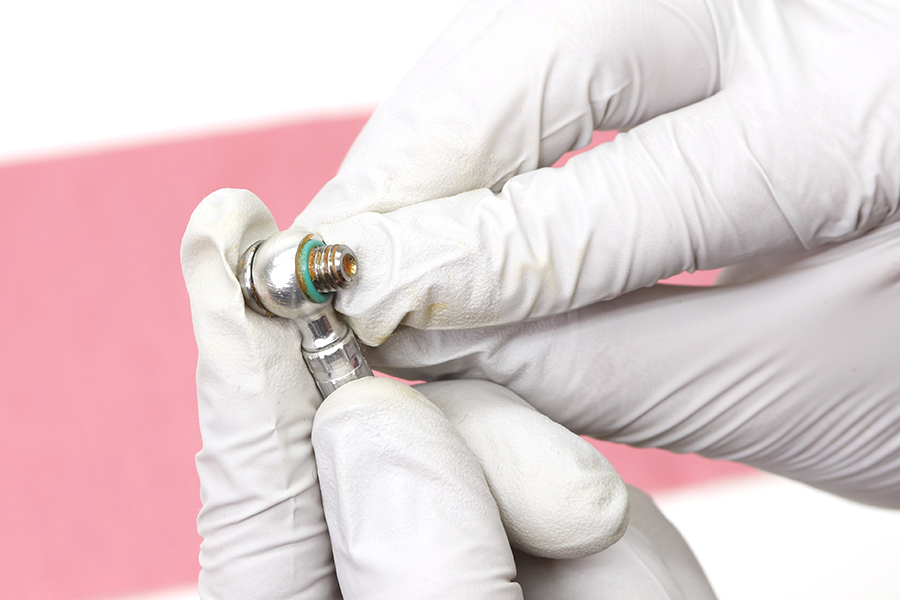
Install the banjo and hose, then hand tighten the banjo bolt.
Visually inspect the banjo bolt hole to confirm the o-ring is not pinched or protruding. If the o-ring is visible, then remove the bolt and reinstall. Pinched o-rings may cause leaks.
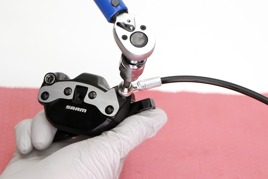
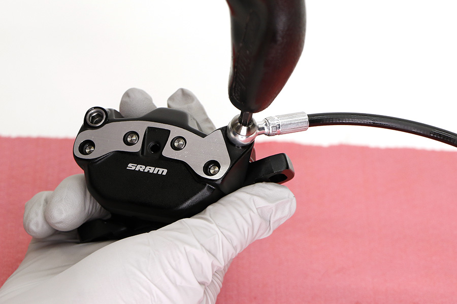
Tighten the banjo bolt.
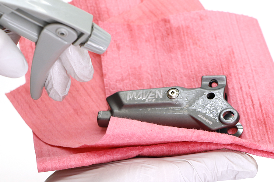
Spray isopropyl alcohol on the caliper and clean it with a shop towel.
Servicing your brakes removes all of the brake fluid from the system. You must bleed the brakes after you service the brake caliper and/or lever.
For brake bleed and brake hose shortening instructions, visit sram.com/service.
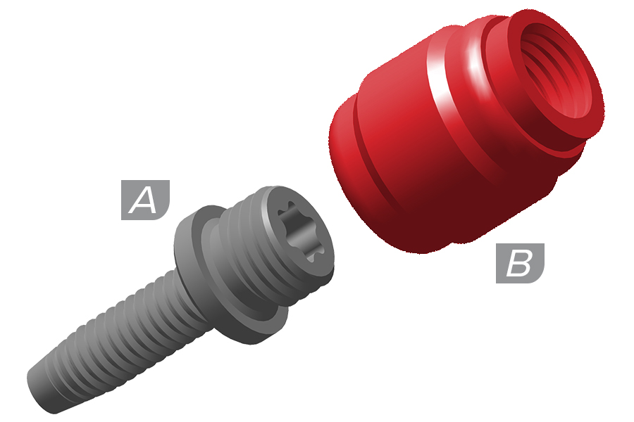
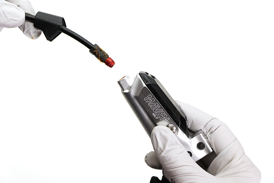
All SRAM brakes that use a compression fitting and hose barb must use a new SJ (Stealth-a-majig) hose barb and a new, red SJ compression fitting upon reassembly.
The factory may have installed a non-red SJ compression fitting, which functioned properly prior to disconnection. Upon reconnection, you must install a new SJ hose barb and a new, red SJ compression fitting.
Brake hoses assembled with non-Stealth-a-majig hose barbs and compression fittings will not function.
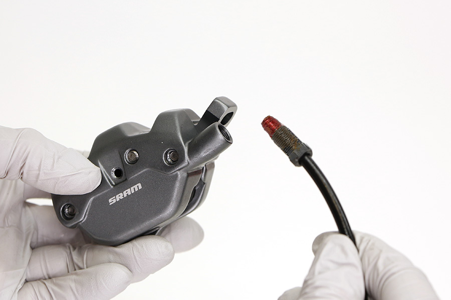
Cut the hose at the caliper end to remove the used barb and compression fitting.


Apply SRAM Hydraulic Brake grease to the hose barb threads.
Thread the hose barb into the hose until it is flush with the end of the hose.
Do not overtighten the hose barb. Overtightening may cause damage to the hose liner.
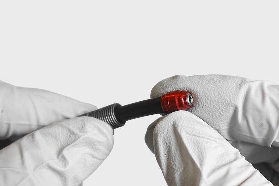

Thread the compression fitting over the hose barb, counter-clockwise, until it is flush or slightly lower than the hose barb.
The compression fitting is reverse threaded.
Apply SRAM Hydraulic Brake grease to the outside of the compression fitting and the threads of the compression nut.
Install the compression fitting and hose into the caliper.
Tighten the compression nut.
Spray isopropyl alcohol on the caliper and clean it with a shop towel.
Servicing your brakes removes all of the brake fluid from the system. You must bleed the brakes after you service the brake caliper and/or lever.
For brake bleed and brake hose shortening instructions, visit sram.com/service.
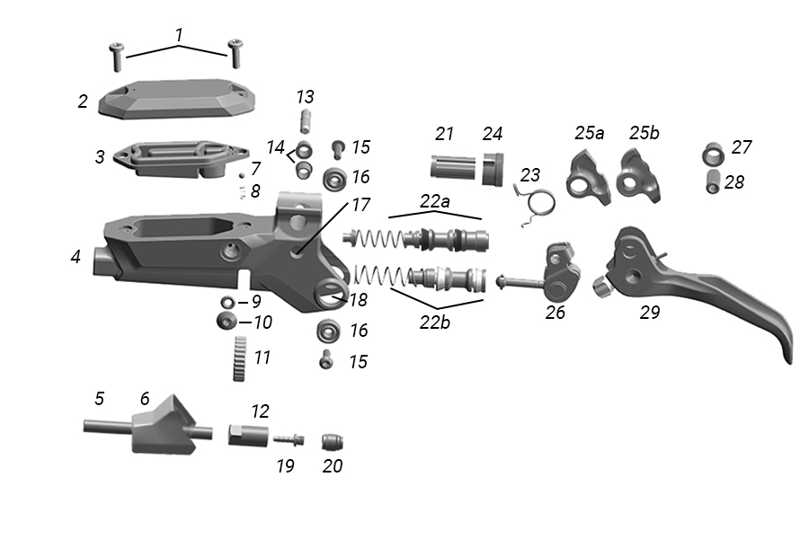
1. Reservoir Bolts | 11. Contact Point Adjustment Dial | 21. Coupling |
2. Reservoir Cap | 12. Compression Nut | 22. Piston Assembly - (a) Stealth-a-majig (b) Standard |
3. Bladder | 14. SwingLink Bushing (2) | 25a. A1: SwingLink Cam - Single Notch |
4. Lever Body | 15. Lever Pivot Bolt | 25b. B1: SwingLink Cam - Double Notch |
5. Hose | 16. Lever Pivot Bearing | 26. A1: SwingLink - Red |
6. Hose Boot | 17. SwingLink Pivot Hole | 26. B1: SwingLink - Gold |
7. Detent Ball | 18. Lever Pivot Hole | 27. Lever Pivot Bushings (2) |
8. Detent Spring | 19. Hose Barb | 28. Lever Pivot Pin |
9. Bleed Port Screw O-Ring (2) | 20. Compression Fitting | 29. Lever Assembly |
10. Bleed Port Screw (2) | 23. Lever Bias Spring | |
13. SwingLink Pivot Pin | 24. Coupler Sleeve |

1. Reservoir Bolts | 11. Compression Nut | 20b. B1: SwingLink Cam - Double Notch |
2. Reservoir Cap | 12. SwingLink Pivot Hole | 21. Pivot Clip |
3. Bladder | 13. Lever Pivot Hole | 22. A1: SwingLink - Red |
4. Lever Body | 14. Hose Barb | 22. B1: SwingLink - Gold |
5. Hose | 15. Compression Fitting | 23. Lever Pivot Bushings (2) |
6. Hose Boot | 16. Piston Assembly - (a) Stealth-a-majig (b) Standard | 24. Lever Pivot Pin |
7. SwingLink Pivot Pin | 17. Snap Ring | 25. Lever Assembly |
8. SwingLink Bushing (2) | 18. Washer | 21. Pivot Clip |
9. Bleed Port Screw O-Ring (2) | 19. Lever Bias Spring | |
10. Bleed Port Screw (2) | 20. A1: SwingLink Cam - Single Notch |
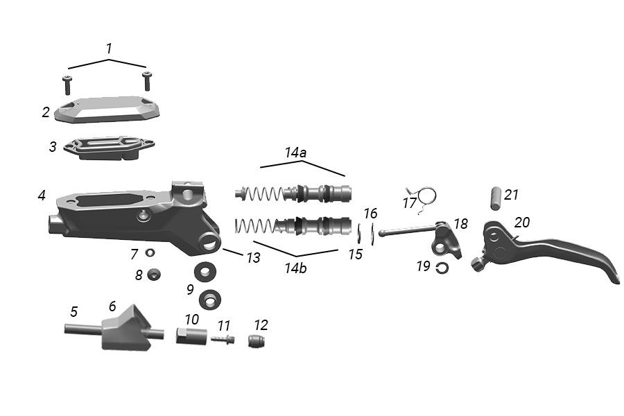
1. Reservoir Bolts | 8. Bleed Port Screw (2) | 15. Washer |
2. Reservoir Cap | 9. Pivot Bushing (2) | 16. Snap Ring |
3. Bladder | 10. Compression Nut | 17. Lever Bias Spring |
4. Lever Body | 11. Hose Barb | 18. Pushrod Cam Bushing Assembly |
5. Hose | 12. Compression Fitting | 19. Pivot Clip |
6. Hose Boot | 13. Lever Pivot Hole | 20. Lever Blade Assembly |
7. Bleed Port Screw O-Ring (2) | 14. Piston Assembly - (a) Stealth-a-majig (b) Standard | 21. Lever Pivot Pin |


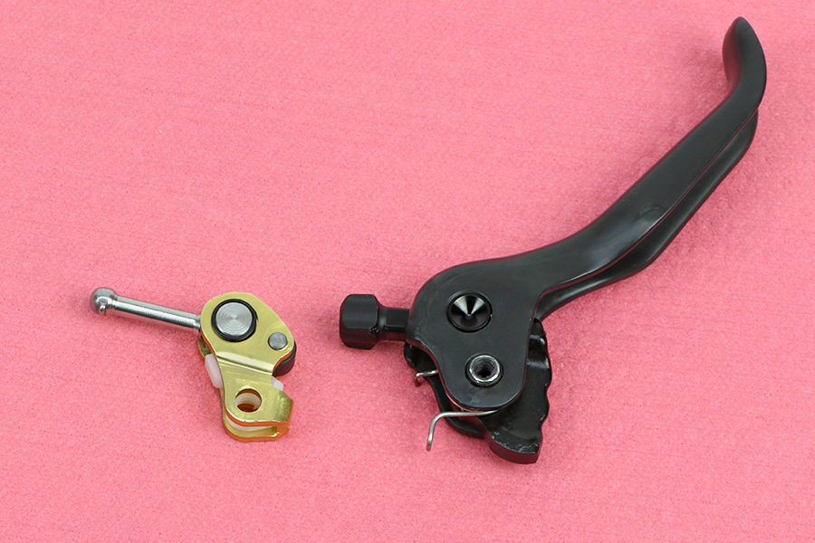
Maven A1 brakes are only compatible with red Swinglinks and single notch SwingLink cams.
Maven B1 brakes are only compatible with gold Swinglinks and double notch SwingLink cams.
For part compatibility, consult the SRAM Spare Parts Catalog at the SRAM Service Site
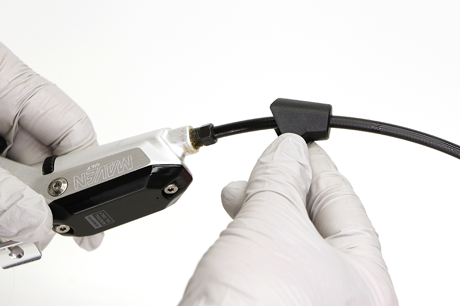
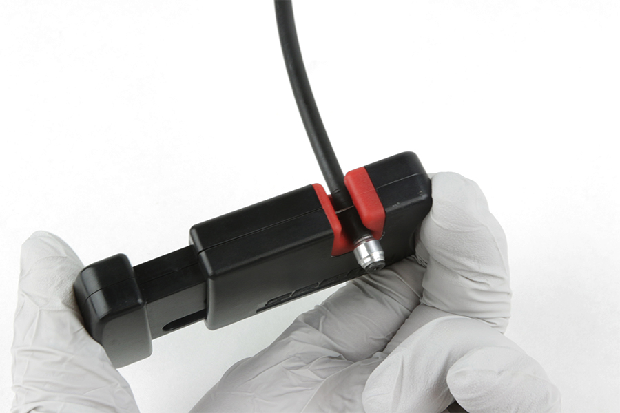
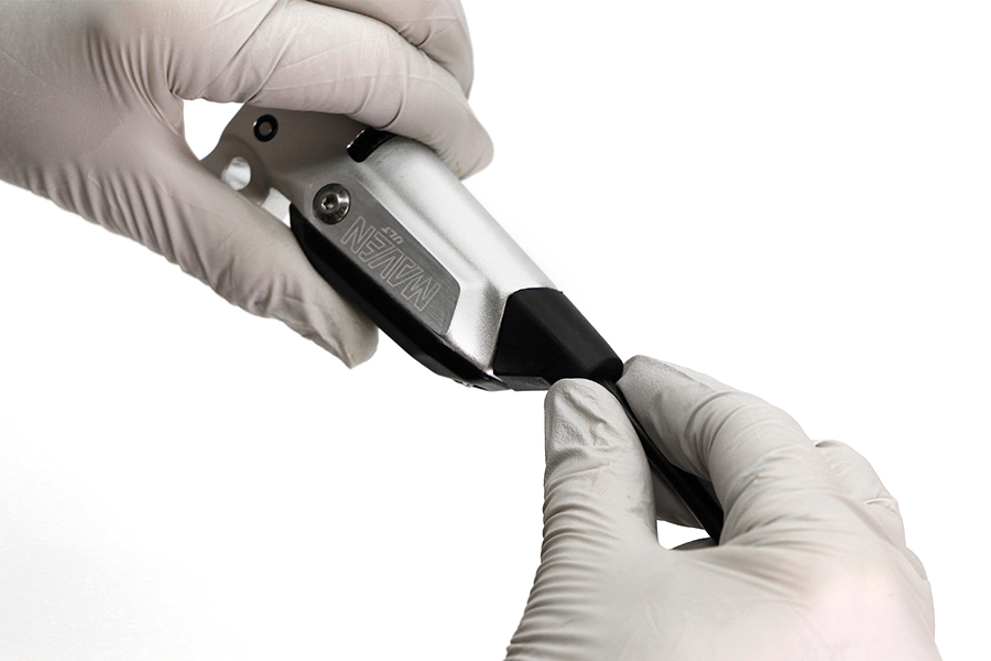
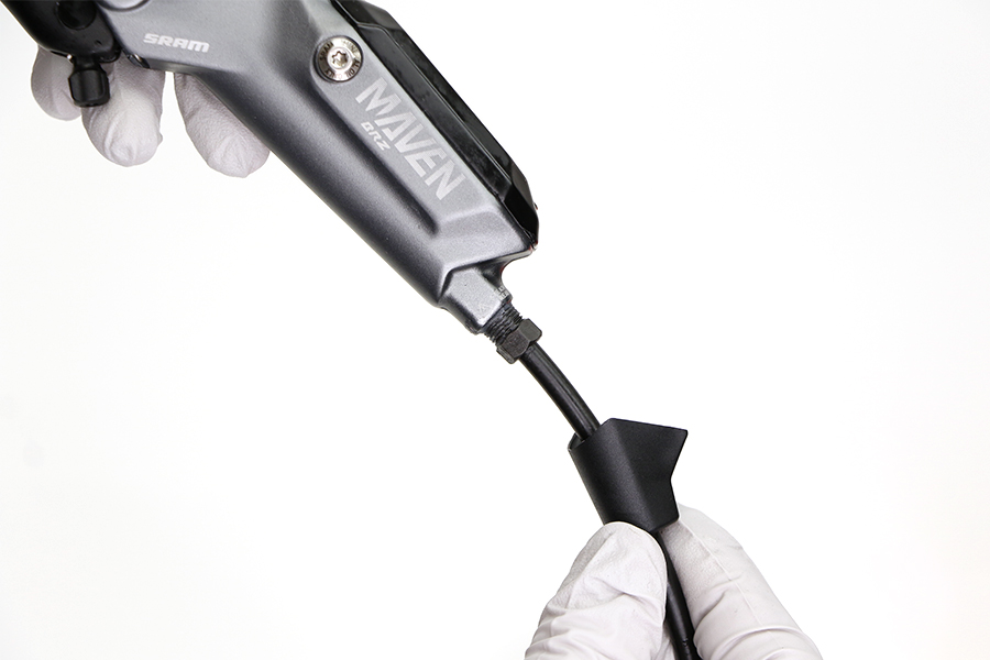
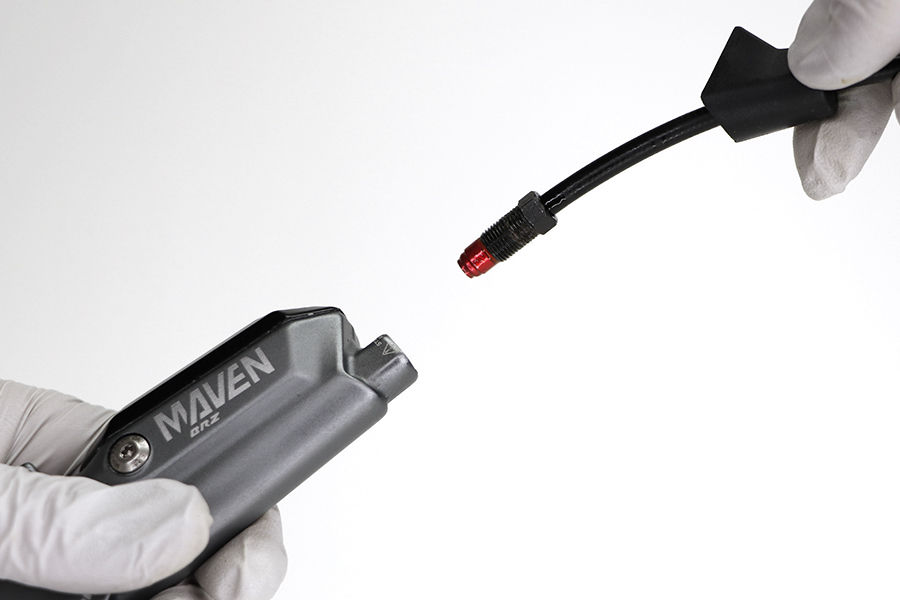
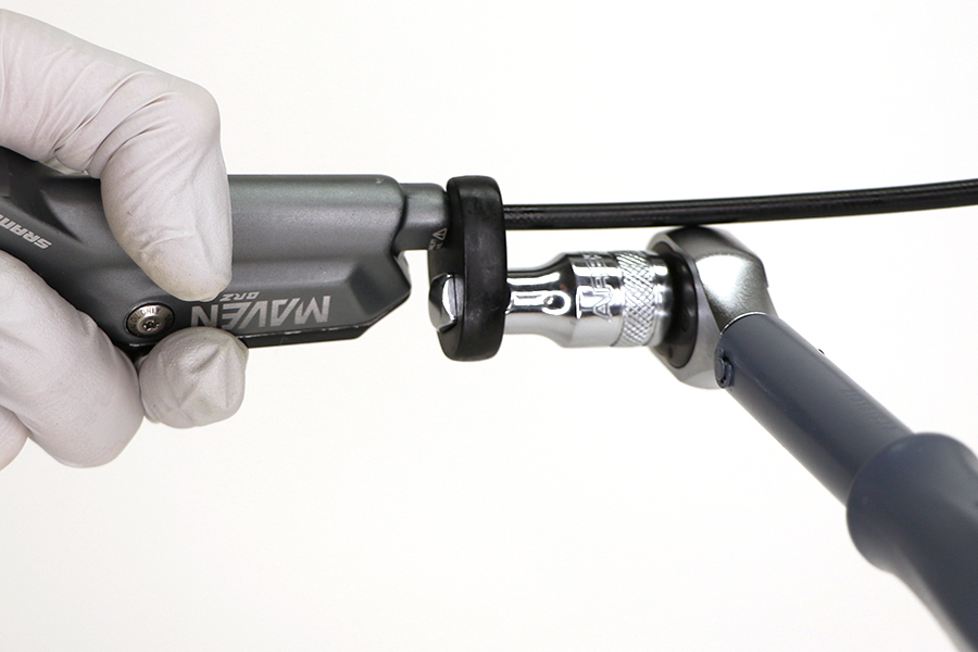
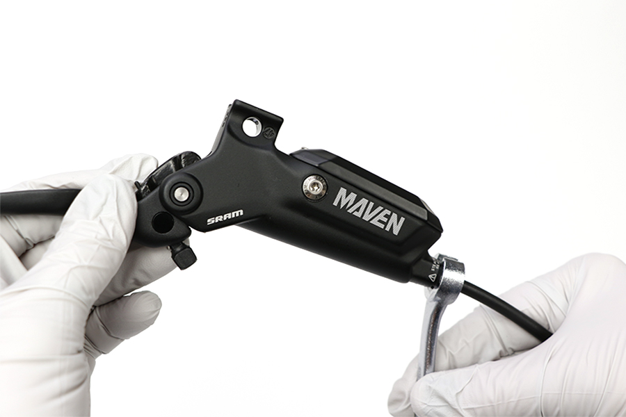
Pull the hose boot off the compression nut and slide it down the hose.


Remove the hose compression nut.
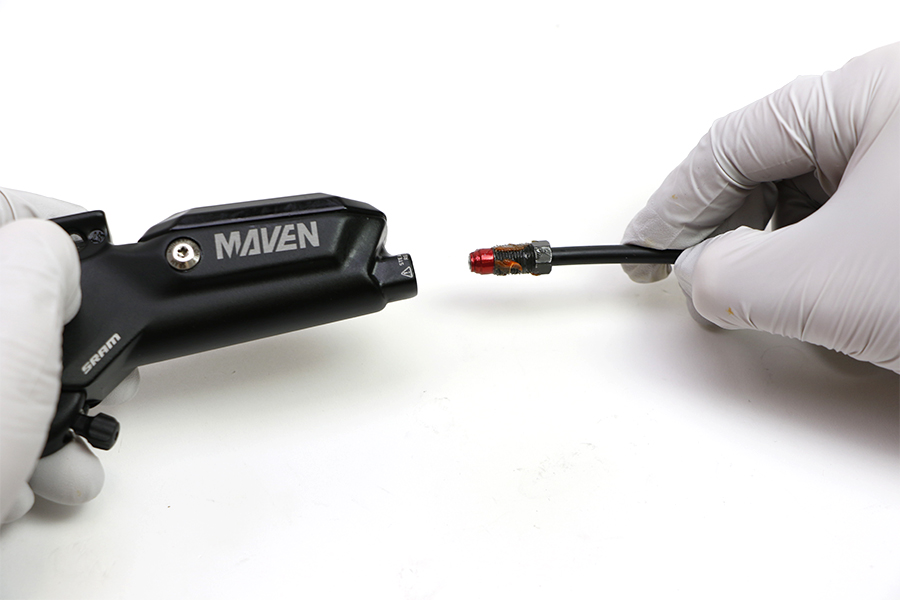
Pull the brake hose and compression fitting from the brake lever body.
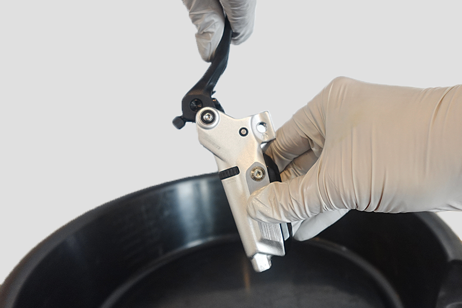
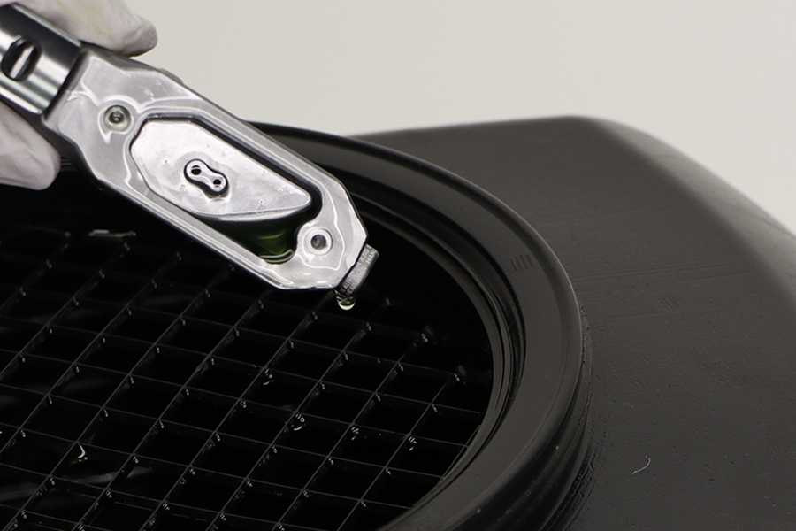
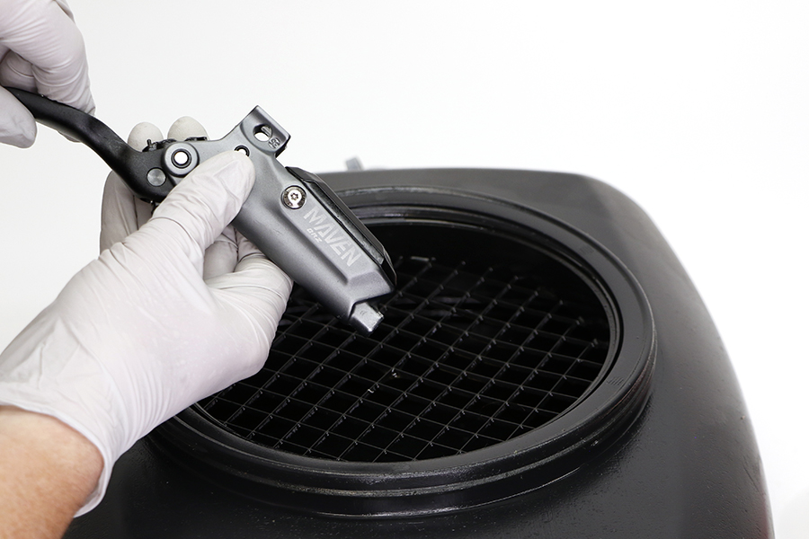
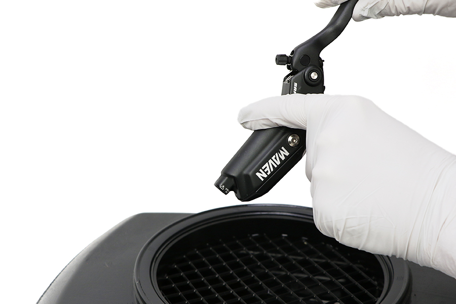
Pour the brake fluid into an oil pan.
Squeeze the lever blade to pump out the excess brake fluid from inside the lever body.
Remove the lever pivot bolt on each side of the lever.
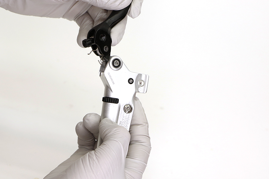
Remove the lever blade assembly from the lever body.

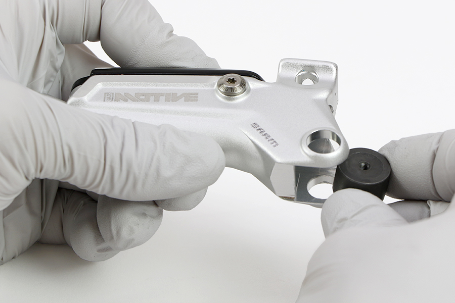
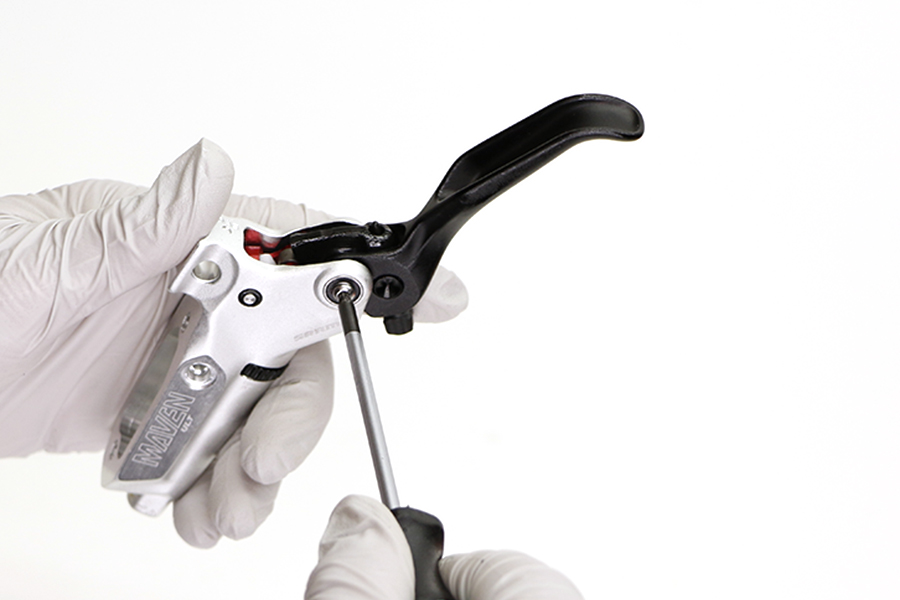
Optional: Lever Bearing Replacement - Removal
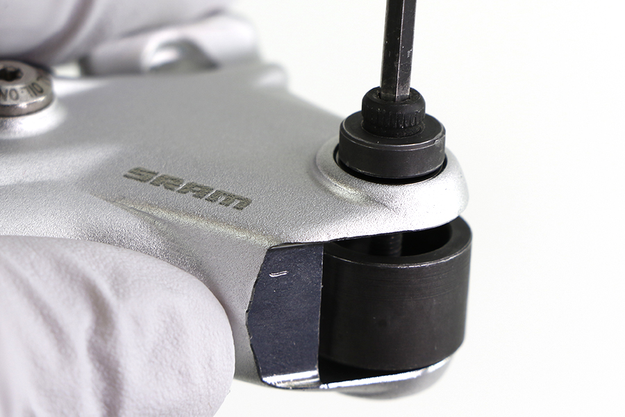
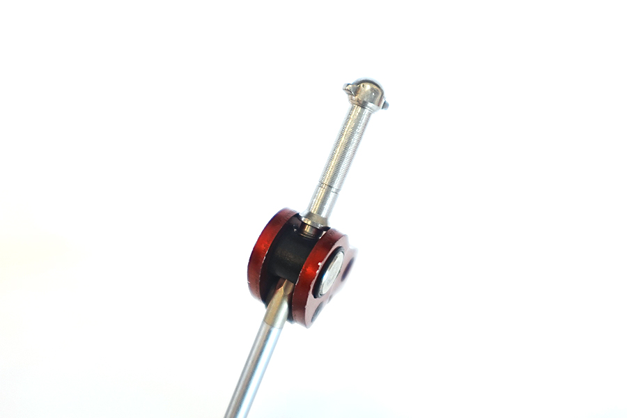
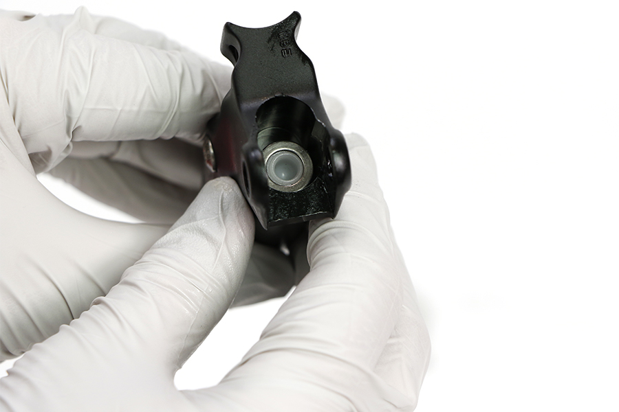
Use the Lever Pivot Bearing Press tool to remove the lever bearing from the lever body.
Install the bearing press cup under the lever bearing with the cup facing toward the bearing.
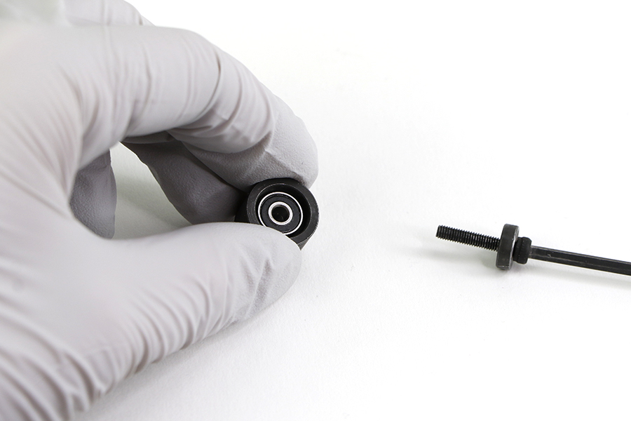
Thread the Lever Pivot Bearing Press screw into the bearing and tool until the bearing releases from the lever body into the cup of the tool.
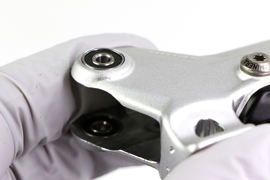
Clean the lever bearing hole.


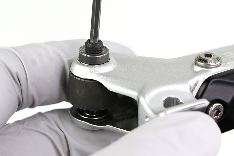
Optional: Lever Bearing Replacement - Installation
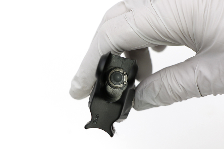
Use the Lever Pivot Bearing Press tool to install the new lever body bearing.
Install the bearing press cup under the lever bearing with the cup facing away from the lever body hole.
Install the new bearing onto the lever body hole. Thread the Lever Pivot Bearing Press screw into the bearing and tool until the bearing is pressed into the lever body.
Make sure the bearing is flush and even as you press the bearing in.
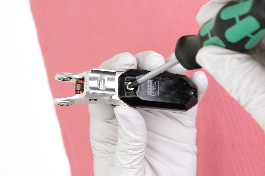
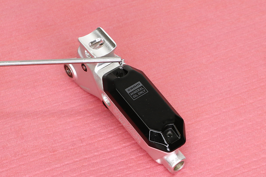
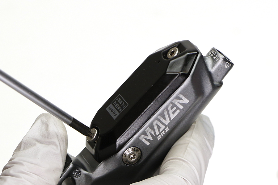
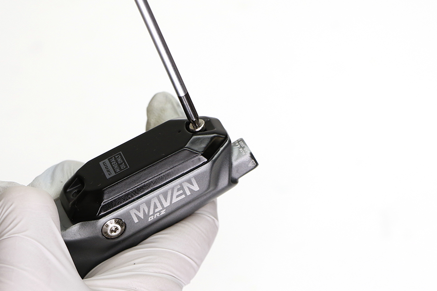
Remove the reservoir cap bolts.
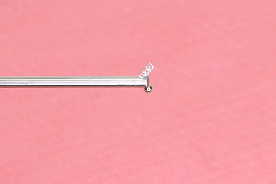
Use a magnet to remove the detent spring and ball from the bolt hole near the lever.


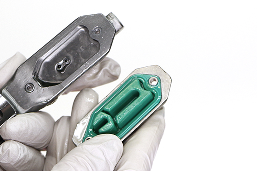
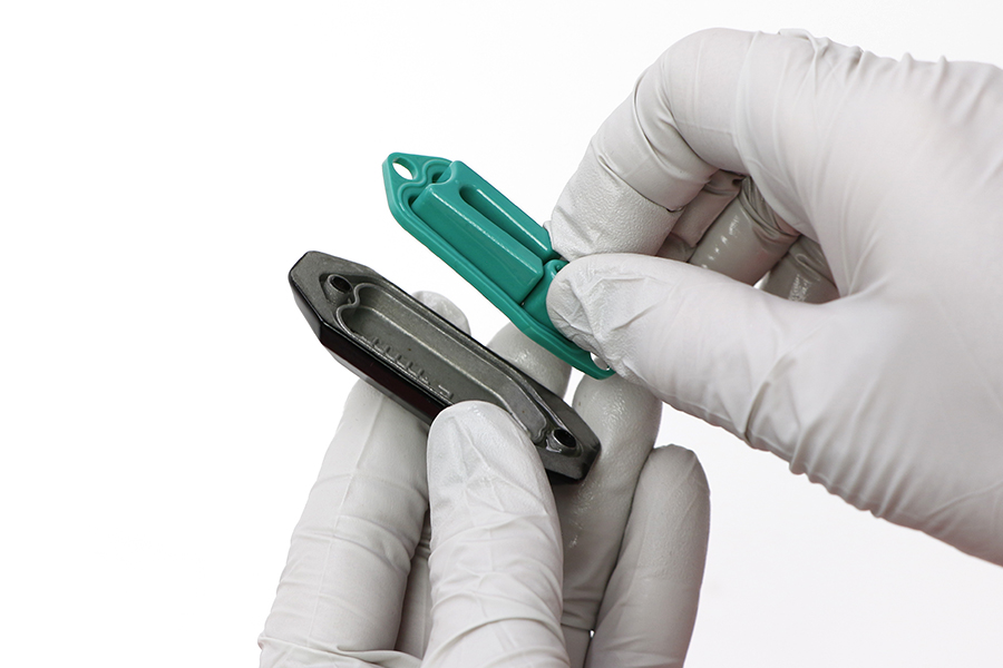
Remove the reservoir cap.
Separate the bladder from the reservoir cap. Spray isopropyl alcohol on the bladder and the reservoir cap and clean them with a shop towel.

Pour any remaining brake oil into an oil pan.
Clean the lever and reservoir.
All components must be completely dry before reinstalling them. Moisture residue from cleaning the bladder can leak out of the bladder as it dries, which can be misinterpreted as a system leak.

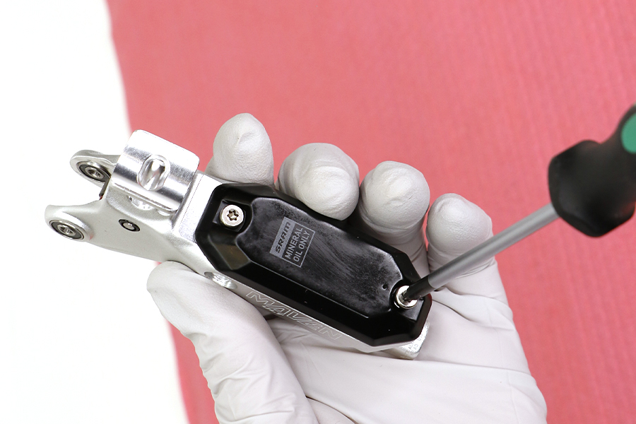
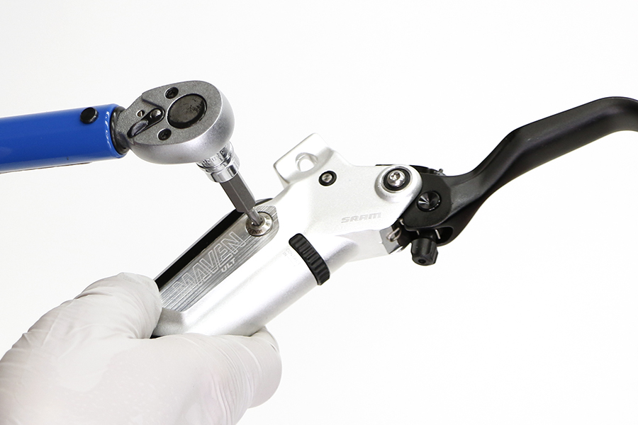
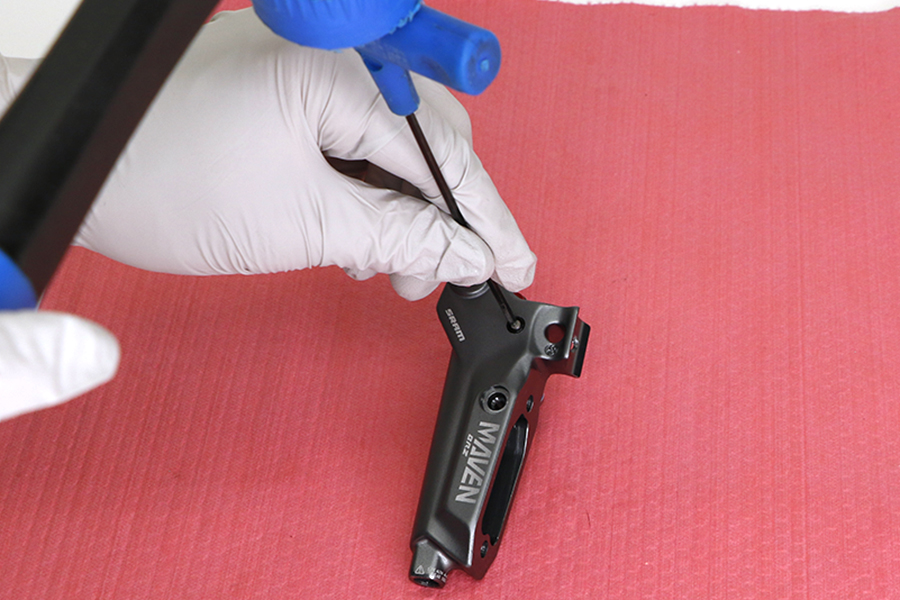
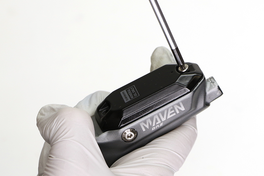
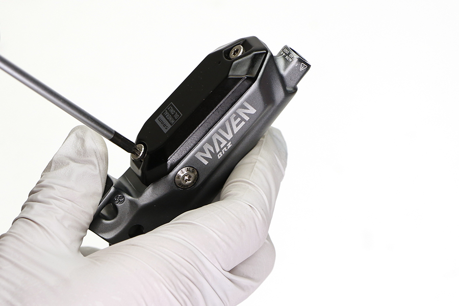
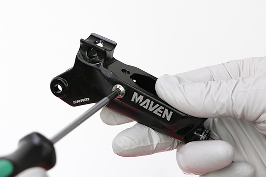
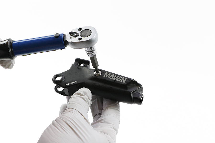
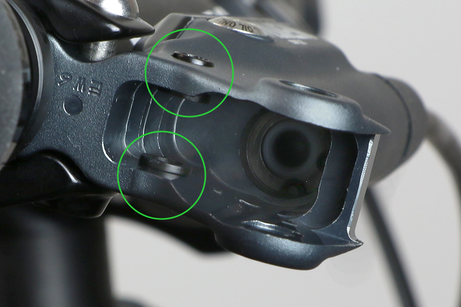
Remove the bleed screw from each side of the lever body.
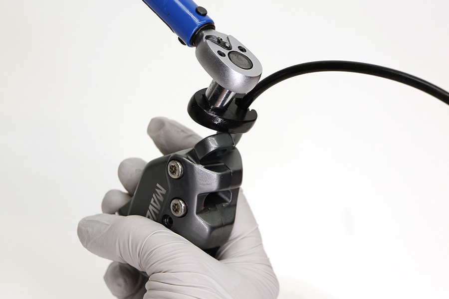
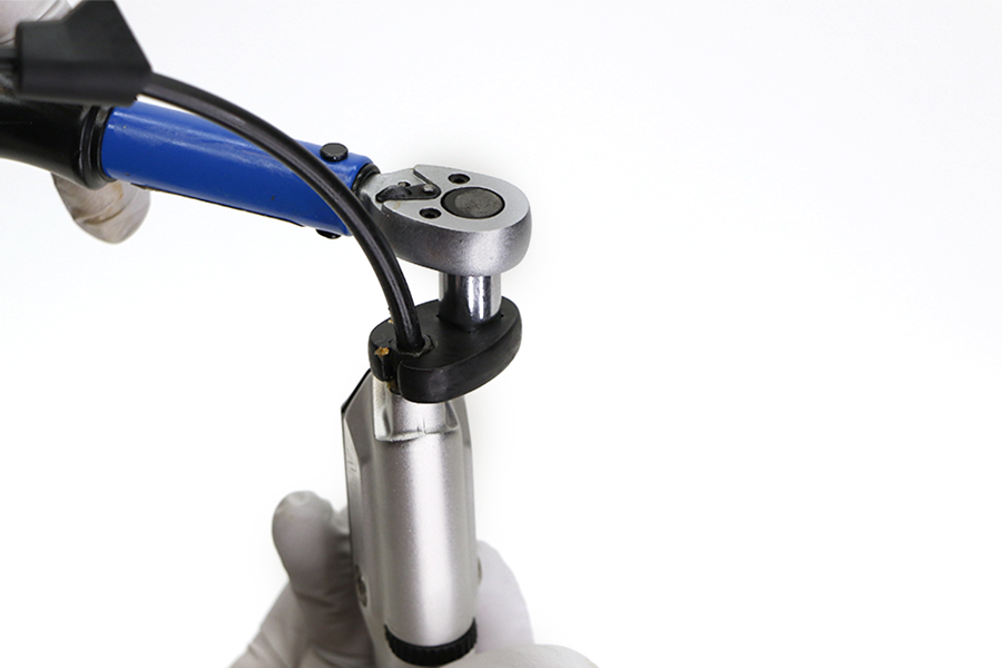
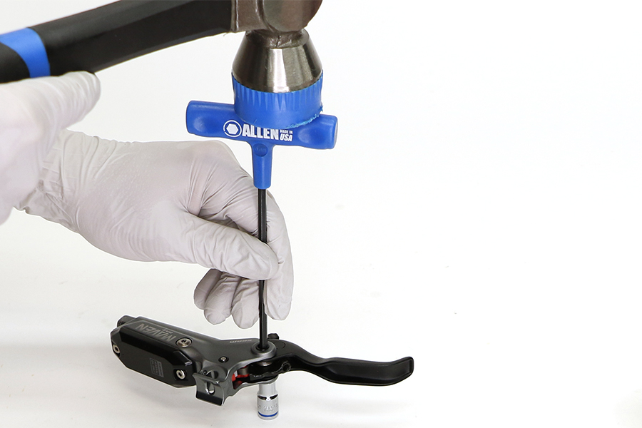
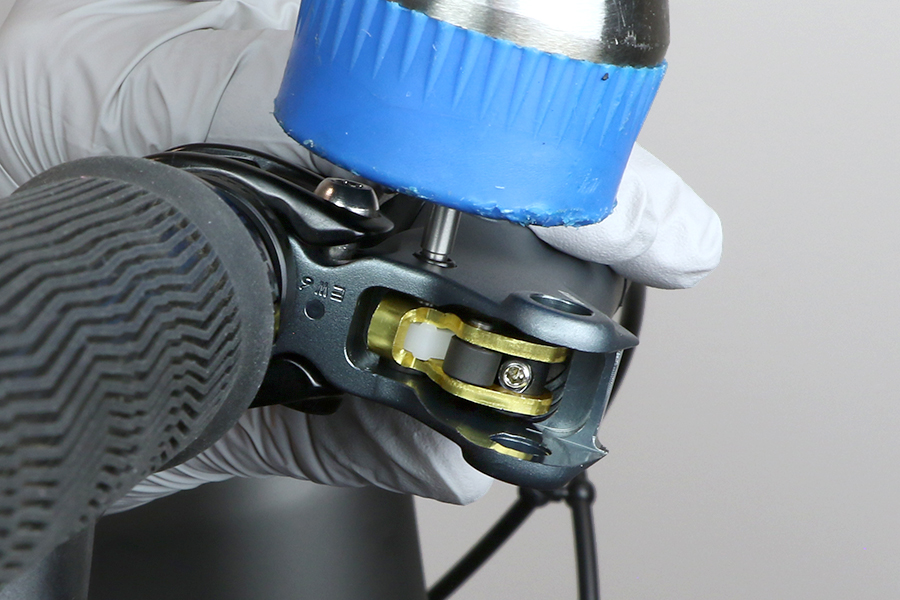
Place the lever pivot on top of a 6 mm socket. Gently tap a 2.5 mm hex wrench with a plastic mallet to remove the pivot pin from the lever body.
Set the pivot pin aside.
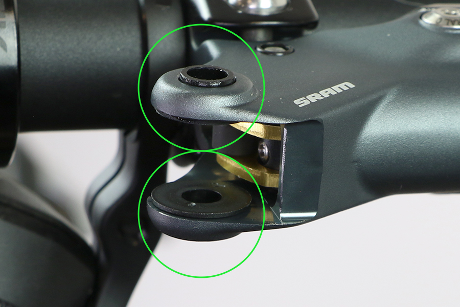
Remove the SwingLink bushings.
The procedure is the same for red and gold SwingLinks.
Remove the SwingLink.


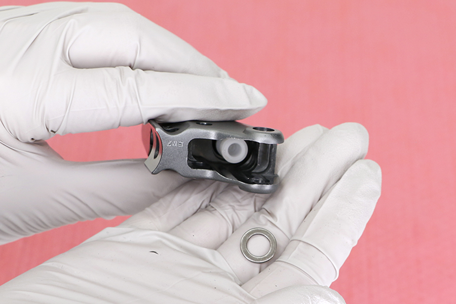
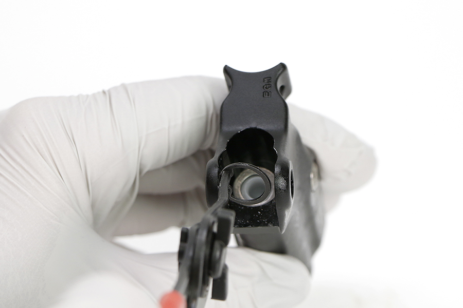
Use a SRAM Lever Internals Assembly tool to unthread the piston sleeve and coupler.
Insert the SRAM Lever Internals Assembly tool into the lever body and align the key slot of the tool with the piston coupler. Use the tool to unthread the sleeve and remove the sleeve and coupler.
If the piston sleeve and coupler are stuck in the lever body, use needle nose pliers to gently remove.

Remove the sleeve from the coupler.
Clean the sleeve and coupler.


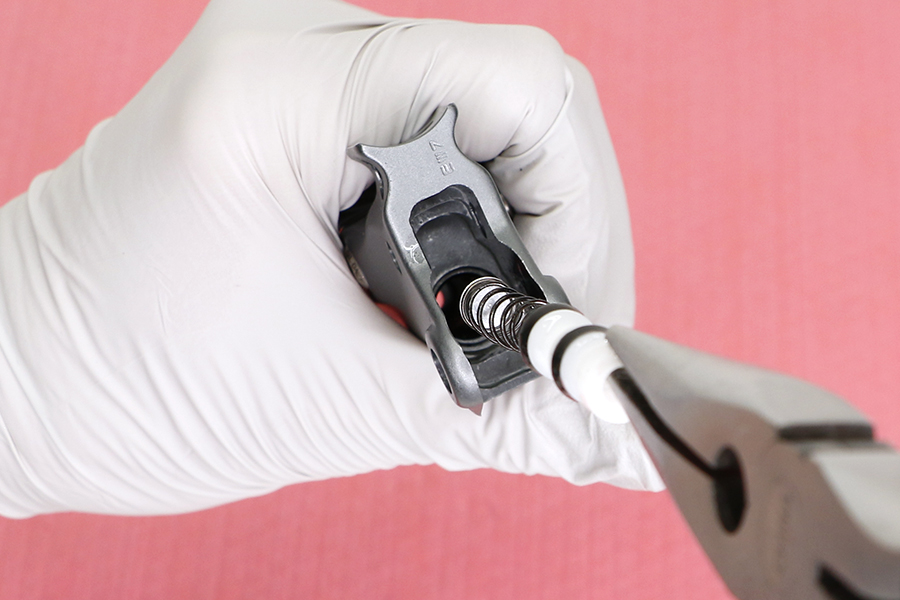
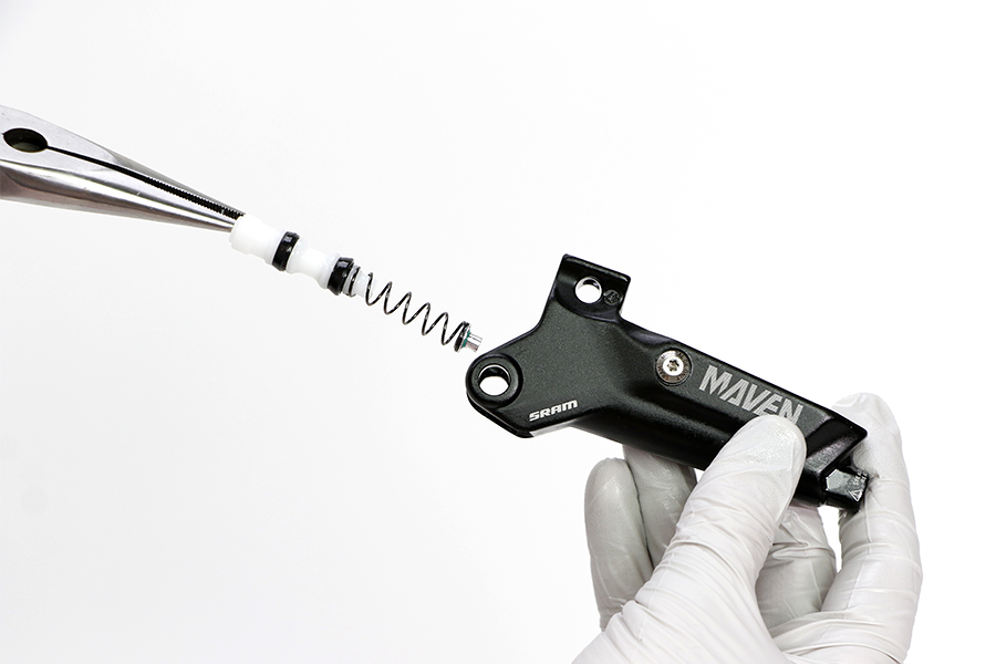
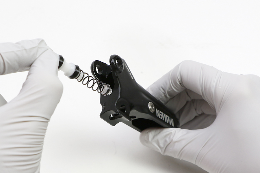
Place a shop towel over the lever body to prevent the piston assembly from ejecting.
Push out the Contact Point Adjustment knob.
Remove the piston assembly from the lever body.
EYE HAZARD
Use safety glasses. The piston assembly is spring loaded and will forcefully eject from the lever body when the Contact Point Adjustment knob is removed.

Clean the lever body.
Brake lever SwingLinks are specific to each brake lever. Consult the Compatibility section for compatibility information.
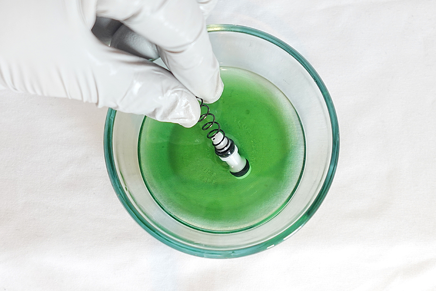
Submerge a new piston in Maxima Mineral Brake oil.
You can also use SRAM Hydraulic Brake grease as a lubricant.

Install the new piston assembly into the lever body.

Use the SRAM Lever Internals Assembly tool to press the piston into the lever body, while you insert the Contact Point Adjustment knob into the Contact Point Adjustment slot.
You should hear a pop sound when the Contact Point Adjustment knob is fully seated in place.

Place the sleeve on the coupler.
The sleeve threads must be oriented toward the base of the coupler.
Use the SRAM Lever Internals Assembly tool to engage and thread the sleeve and coupler onto the piston assembly.
Engage the slots on the sleeve with the Contact Point Adjustment knob and continue to thread the SRAM Lever Internals Assembly tool in a clockwise rotation until it stops.

Install the SwingLink bushings.
If the SwingLink bushings fall out easily, apply a small amount of SRAM Hydraulic Brake grease to the bushings to help hold them in place.
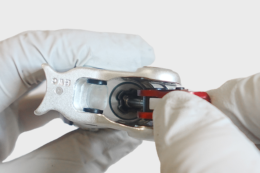
Use a 2 mm hex wrench to rotate the SwingLink bolt clockwise until the pushrod is fully extended. Do not over tighten.
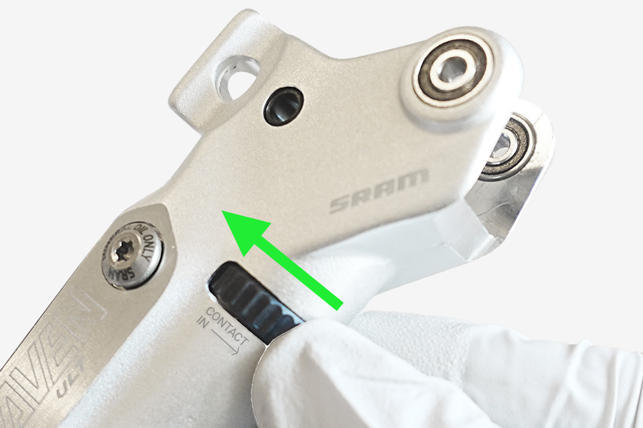
Rotate the Contact Point Adjustment dial in the opposite direction of the arrow on the lever body until it stops.
Install the SwingLink pushrod so the flared end is seated in the coupler sleeve. The procedure is the same for red and gold SwingLinks.
It may be necessary to rotate the Contact Point Adjustment dial a 1/4 turn so the pushrod and coupler are seated evenly in the lever body.
Rotate the Contact Point Adjustment dial in and out to verify it moves easily. If there is resistance, repeat step 7 and 8.


Align the holes of the SwingLink and the SwingLink bushings.
Press the pivot pin into the hole until it is flush with the lever body.
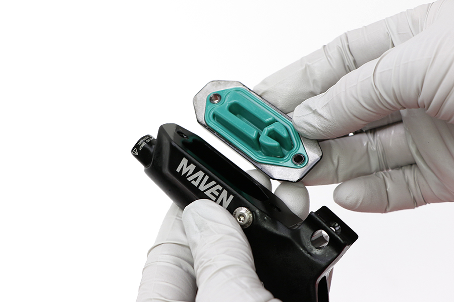
Press the bladder into the reservoir cap. Make sure the bladder is seated into the reservoir cap.
Install the reservoir cap and bladder assembly onto the lever body.


Install a new detent ball followed by a detent spring into the lever body reservoir hole closest to the lever blade.
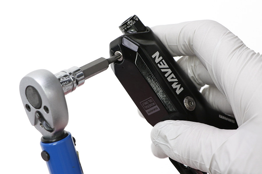
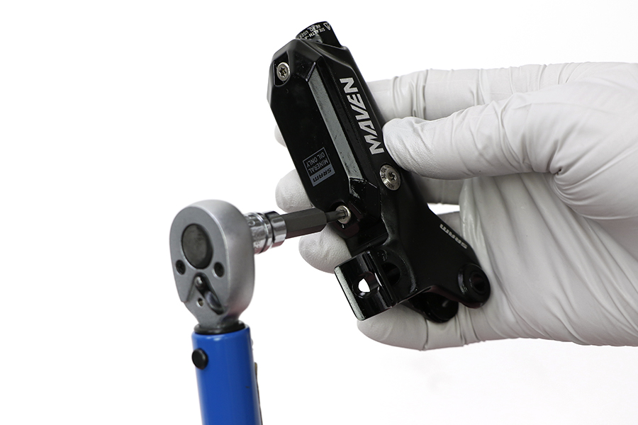
Install and tighten each reservoir cap bolt.
Brake lever blades and SwingLink cams are specific to each brake lever. Consult the Compatibility section for compatibility information.

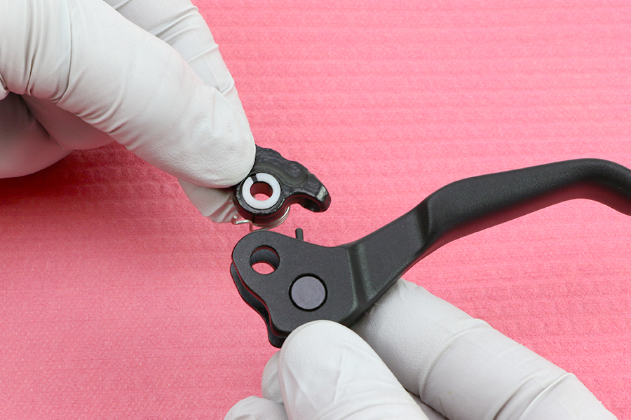
Adjust the long side of the spring so it is pressing on the surface of the lever body.
Align the pivot holes of the lever blade with the pivot holes in the lever body.
Install the lever blade.
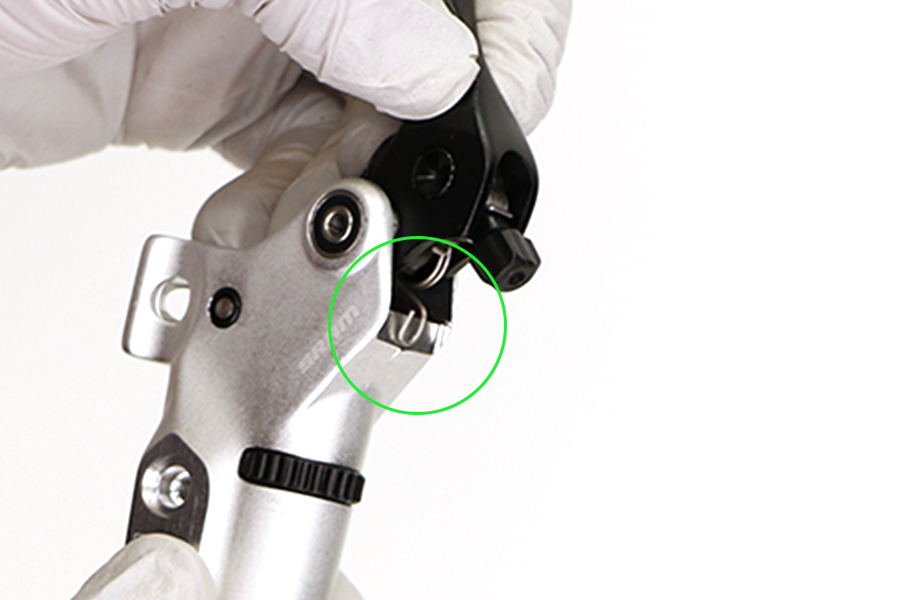
Make sure the lever bias spring is seated properly in the lever. The short end of the spring must press against the lever blade, while the long end of the spring must press against the lever body. If the return spring is not seated properly, you will not be able to adjust the reach of the lever blade.

Apply a small amount of Loctite Blue 242 or equivalent onto each pivot bolt.

Thread each pivot bolt into the bearings on each side of the lever body.
Tighten each pivot bolt.

Apply SRAM Hydraulic Brake grease to the new o-rings. Install the o-rings on the bleed screws.
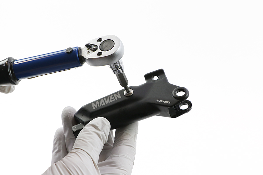
Install the bleed screws into each side of the lever body.
All SRAM brakes that use a compression fitting and hose barb must use a new SJ (Stealth-a-majig) hose barb and a new, red SJ compression fitting upon reassembly.
The factory may have installed a non-red SJ compression fitting, which functioned properly prior to disconnection. Upon reconnection, you must install a new SJ hose barb and a new, red SJ compression fitting.
Brake hoses assembled with non-Stealth-a-majig hose barbs and compression fittings will not function.

Cut the hose at the lever end to remove the used barb and compression fitting.
Verify the compression nut and lever boot remain installed on the hose.
Apply SRAM Hydraulic Brake grease to the hose barb threads.
Thread the hose barb into the hose until it is flush with the end of the hose.
Do not overtighten the hose barb. Overtightening may cause damage to the hose liner.
Thread the compression fitting over the hose barb, counter-clockwise, until it is flush or slightly lower than the hose barb.
The compression fitting is reverse threaded.
Apply SRAM Hydraulic Brake grease to the outside of the compression fitting and the threads of the compression nut.
Install the compression fitting and hose into the lever.
Tighten the compression nut.

Install the lever boot.
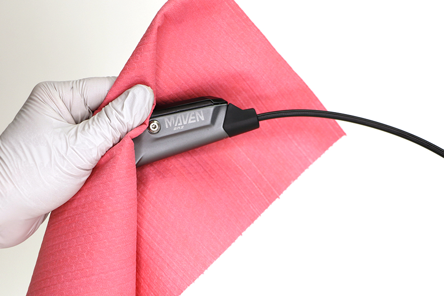
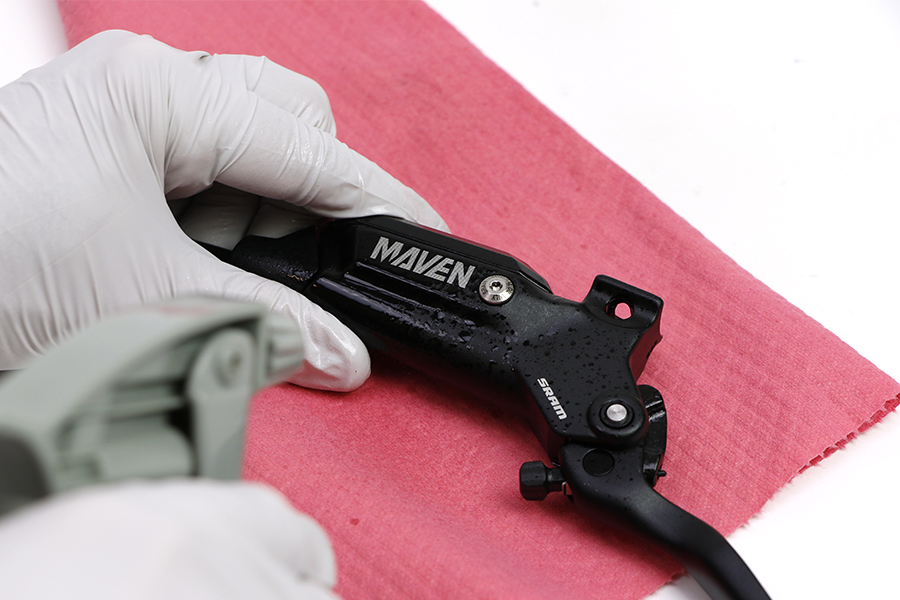
Spray isopropyl alcohol on the lever and clean it with a shop towel.
Pull the hose boot off the compression nut and slide it down the hose.

Remove the hose compression nut.
Pull the brake hose and compression fitting from the brake lever body.
Pour the brake fluid into an oil pan.
Squeeze the lever blade to pump out the excess brake fluid from inside the lever body.
Place the lever pivot on top of a 6 mm socket. Gently tap a 4 mm hex wrench with a plastic mallet to remove the lever pivot pin from the lever body.
Set the pivot pin aside.
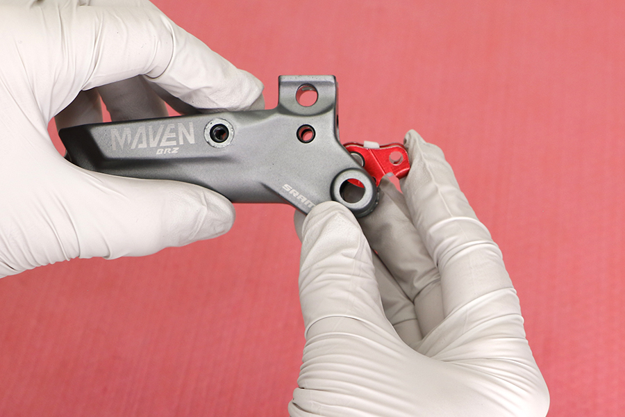
Remove the lever blade.
The lever assembly will separate into four pieces when removed from the lever body: SwingLink cam, lever bias spring, pivot clip, and blade assembly.
Remove the pivot bushings.
Remove the reservoir cap bolts.
Remove the reservoir cap and bladder.
Separate the bladder from the reservoir cap. Spray isopropyl alcohol on the bladder and the reservoir cap and clean them with a shop towel.
Pour any remaining brake oil into an oil pan.
Clean the lever and reservoir.
All components must be completely dry before reinstalling them. Moisture residue from cleaning the bladder can leak out of the bladder as it dries, which can be misinterpreted as a system leak.
Remove the bleed screw from each side of the lever body.
Place the SwingLink pivot on top of a 6 mm socket. Gently tap a 2.5 mm hex wrench with a plastic mallet to remove the SwingLink pivot pin from the lever body.
Set the pivot pin aside.
Remove the SwingLink. The procedure is the same for red and gold SwingLinks.
Remove the SwingLink bushings.
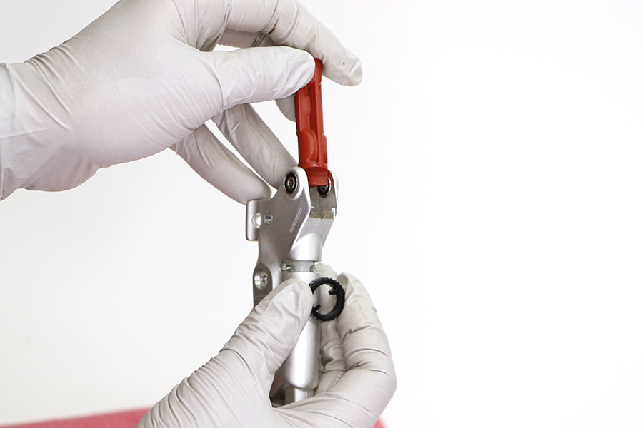
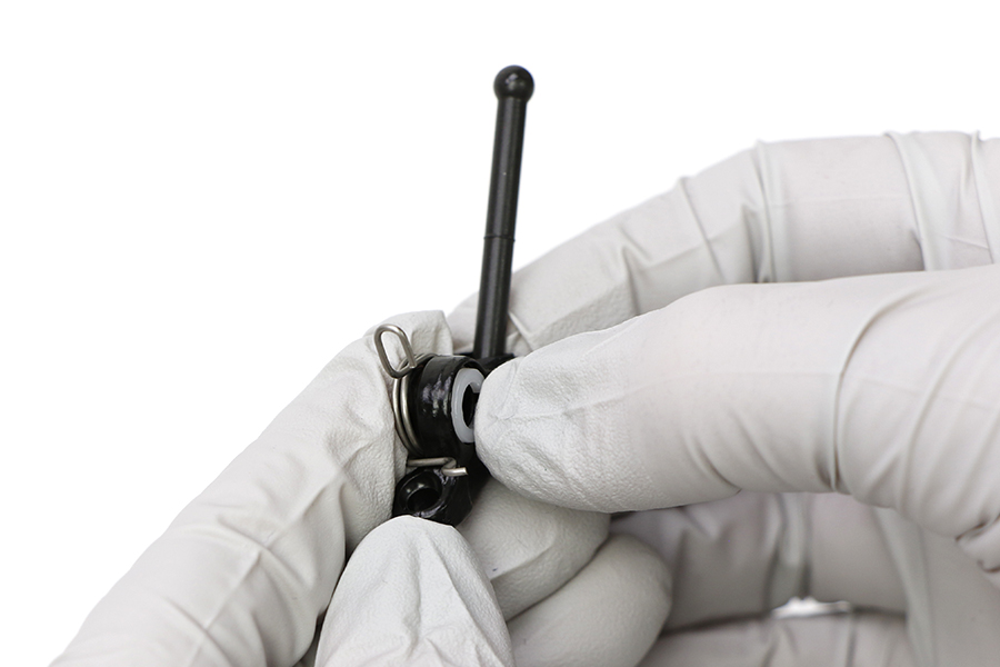
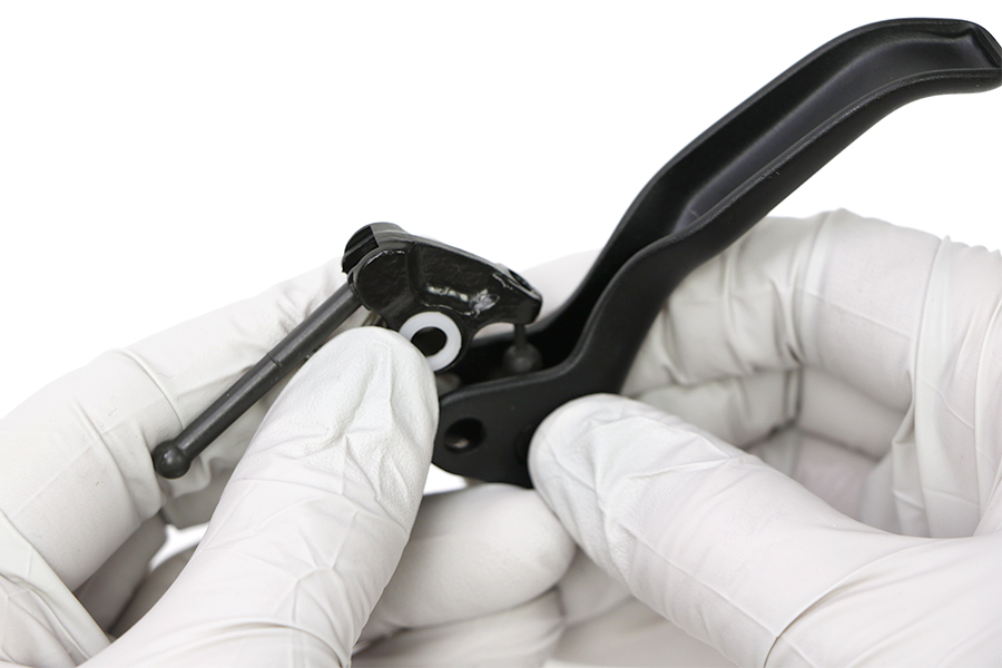
Use long-tipped internal snap ring pliers to apply downward pressure to the lever body and remove the snap ring. Turn the lever body upside down to allow the washer to fall out of the body.
Use needle nose pliers to remove the piston assembly.
Brake lever SwingLinks are specific to each brake lever. Consult the Compatibility section for compatibility information.
Submerge a new piston in Maxima Mineral Brake Oil. You can also use SRAM Hydraulic Brake grease as a lubricant.

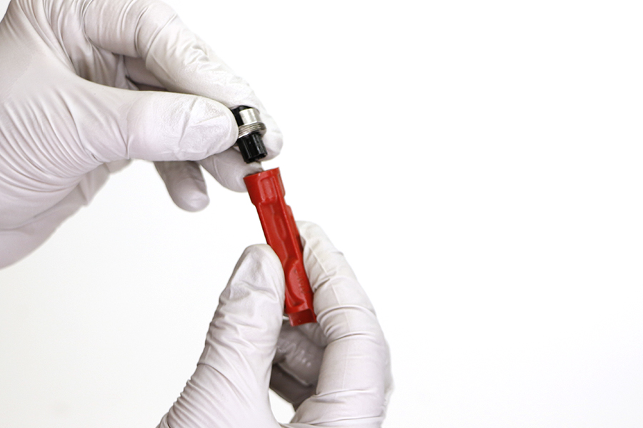
Install the new piston assembly into the lever body.

lnstall the washer on the piston assembly.
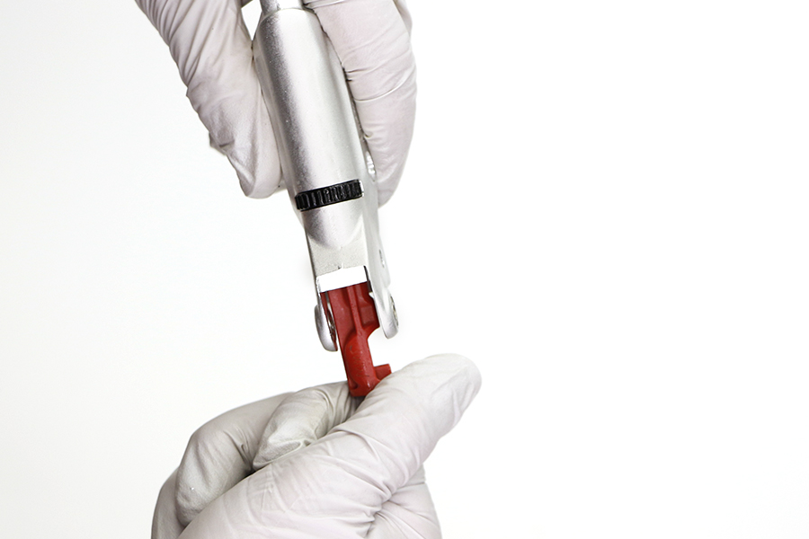
Use long-tipped internal snap ring pliers to push the piston assembly into the lever body, and secure the snap ring in its groove.


Install the SwingLink bushings.
If the SwingLink bushings fall out easily, apply a small amount of SRAM Hydraulic Brake grease to the bushings to help hold them in place.
Install the SwingLink pushrod so it is seated in the piston.
Align the holes of the SwingLink and the SwingLink bushings.
Press the pivot pin into the hole until it is flush with the lever body.
Apply SRAM Hydraulic Brake grease to the new o-rings. Install the o-rings on the bleed screws.
Install the bleed screws into each side of the lever body.
Press the bladder into the reservoir cap. Make sure the bladder is seated into the reservoir cap.
Install the reservoir cap and bladder assembly onto the lever body.
Install and tighten each reservoir cap bolt.
Brake lever blades and SwingLink cams are specific to each brake lever. Consult the Compatibility section for compatibility information.


Install the bushings into each side of the lever.


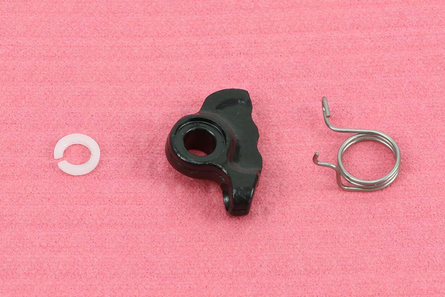
Install the lever bias spring and pivot clip onto the SwingLink cam.
Hold the spring and pivot clip in place and install the hole on the SwingLink cam onto the reach adjust pin in the lever blade.

Adjust the long side of the spring so it is pressing on the surface of the lever body.
Align the holes in the cam and lever blade with the holes in the lever body.
Install the pivot pin through the holes. Push the pivot pin through the lever body so that it is flush with the lever body on both sides. If needed, use a plastic mallet to gently push the pivot pin in until it is seated flush with the lever body holes.
Make sure the lever bias spring is seated properly in the lever. The short end of the spring must press against the lever blade, while the long end of the spring must press against the lever body. If the return spring is not seated properly, you will not be able to adjust the reach of the lever blade.
All SRAM brakes that use a compression fitting and hose barb must use a new SJ (Stealth-a-majig) hose barb and a new, red SJ compression fitting upon reassembly.
The factory may have installed a non-red SJ compression fitting, which functioned properly prior to disconnection. Upon reconnection, you must install a new SJ hose barb and a new, red SJ compression fitting.
Brake hoses assembled with non-Stealth-a-majig hose barbs and compression fittings will not function.
Cut the hose at the lever end to remove the used barb and compression fitting.
Verify the compression nut and lever boot remain installed on the hose.
Apply SRAM Hydraulic Brake grease to the hose barb threads.
Thread the hose barb into the hose until it is flush with the end of the hose.
Do not overtighten the hose barb. Overtightening may cause damage to the hose liner.
Thread the compression fitting over the hose barb, counter-clockwise, until it is flush or slightly lower than the hose barb.
The compression fitting is reverse threaded.
Apply SRAM Hydraulic Brake grease to the outside of the compression fitting and the threads of the compression nut.
Install the compression fitting and hose into the lever.
Tighten the compression nut.

Install the lever boot.
Spray isopropyl alcohol on the lever and clean it with a shop towel.
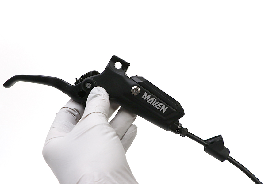
This concludes the service of your SRAM Maven brake.
Servicing your brakes removes all of the brake fluid from the system. You must bleed the brakes after you service the brake caliper and/or lever.
For brake bleed and brake hose shortening instructions, visit sram.com/service.
Pull the hose boot off the compression nut and slide it down the hose.
Remove the hose compression nut.
Pull the brake hose and compression fitting from the brake lever body.
Pour the brake fluid into an oil pan.
Squeeze the lever blade to pump out the excess brake fluid from inside the lever body.
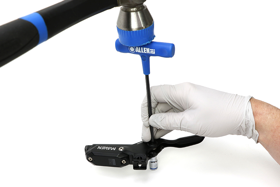
Place the lever pivot on top of a socket. Gently tap a 4 mm hex wrench with a plastic mallet to remove the lever pivot pin from the lever body.
Set the pivot pin aside.
Remove the lever blade.
The lever assembly will separate into three pieces when removed from the lever body: cam pushrod assembly, lever bias spring, pivot clip, and blade assembly.
Remove the pivot bushings.
Remove the reservoir cap bolts.

Remove the reservoir cap and bladder. Pour any remaining brake oil into an oil pan.
Separate the bladder from the reservoir cap. Spray isopropyl alcohol on the bladder and the reservoir cap and clean them with a shop towel. Clean the lever and reservoir.
All components must be completely dry before reinstalling them. Moisture residue from cleaning the bladder can leak out of the bladder as it dries, which can be misinterpreted as a system leak.
Remove the bleed screw from each side of the lever body.

Use long-tipped internal snap ring pliers to apply downward pressure to the lever body and remove the snap ring. Turn the lever body upside down to allow the washer to fall out of the body.
Use needle nose pliers to remove the piston assembly.
Submerge a new piston in Maxima Mineral Brake Oil. You can also use SRAM Hydraulic Brake grease as a lubricant.
Install the new piston assembly into the lever body.
lnstall the washer on the piston assembly.
Use long-tipped internal snap ring pliers to push the piston assembly into the lever body, and secure the snap ring in its groove.
Apply SRAM Hydraulic Brake grease to the new o-rings. Install the o-rings on the bleed screws.
Install the bleed screws into each side of the lever body.
Press the bladder into the reservoir cap. Make sure the bladder is seated into the reservoir cap.
Install the reservoir cap and bladder assembly onto the lever body.
Install and tighten each reservoir cap bolt.
Install the bushings into each side of the lever.
Install the lever bias spring and pivot clip onto the cam pushrod assembly.
Hold the spring and pivot clip in place and install the hole on the cam pushrod assembly onto the reach adjust pin in the lever blade.
Install the pushrod of the lever blade assembly onto the piston inside the lever body. Adjust the long side of the spring so it is pressing on the surface of the lever body.
Align the holes in the cam and lever blade with the holes in the lever body.
Install the pivot pin through the holes. Push the pivot pin through the lever body so that it is flush with the lever body on both sides. If needed, use a plastic mallet or a work bench surface to gently push the pivot pin in until it is seated flush with the lever body holes.
Make sure the lever bias spring is seated properly in the lever. The short end of the spring must press against the lever blade, while the long end of the spring must press against the lever body. If the return spring is not seated properly, you will not be able to adjust the reach of the lever blade.
All SRAM brakes that use a compression fitting and hose barb must use a new SJ (Stealth-a-majig) hose barb and a new, red SJ compression fitting upon reassembly.
The factory may have installed a non-red SJ compression fitting, which functioned properly prior to disconnection. Upon reconnection, you must install a new SJ hose barb and a new, red SJ compression fitting.
Brake hoses assembled with non-Stealth-a-majig hose barbs and compression fittings will not function.
Cut the hose at the lever end to remove the used barb and compression fitting.
Verify the compression nut and lever boot remain installed on the hose.
Apply SRAM Hydraulic Brake grease to the hose barb threads.
Thread the hose barb into the hose until it is flush with the end of the hose.
Do not overtighten the hose barb. Overtightening may cause damage to the hose liner.
Thread the compression fitting over the hose barb, counter-clockwise, until it is flush or slightly lower than the hose barb.
The compression fitting is reverse threaded.
Apply SRAM Hydraulic Brake grease to the outside of the compression fitting and the threads of the compression nut.
.jpg)
Install the compression fitting and hose into the lever.
Tighten the compression nut.
Install the lever boot.
Spray isopropyl alcohol on the lever and clean it with a shop towel.
This concludes the service of your SRAM Maven brake.
Servicing your brakes removes all of the brake fluid from the system. You must bleed the brakes after you service the brake caliper and/or lever.
For brake bleed and brake hose shortening instructions, visit sram.com/service.
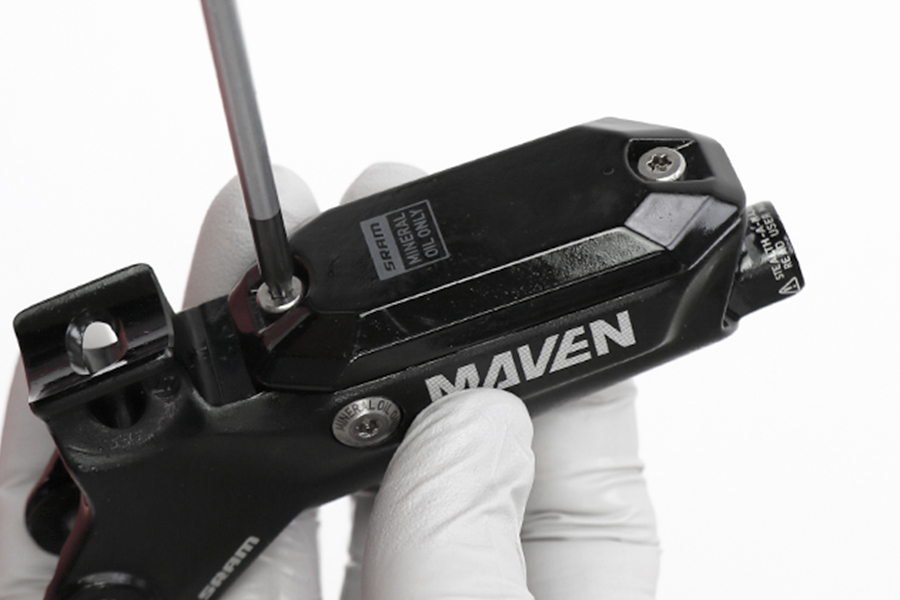
Maven Ultimate brakes are showing in the following procedure. The process is the same for Maven Silver brakes.
For Brake Lever Tuning Kit contents and details, consult the SRAM Spare Parts Catalog at the SRAM Service Site.
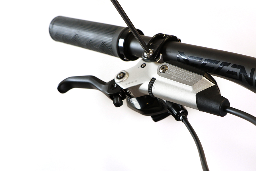
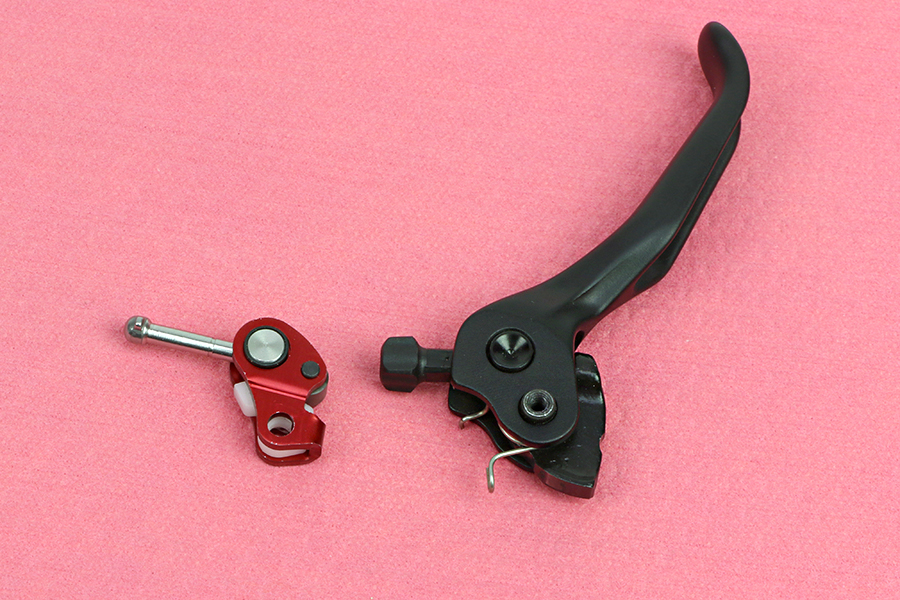
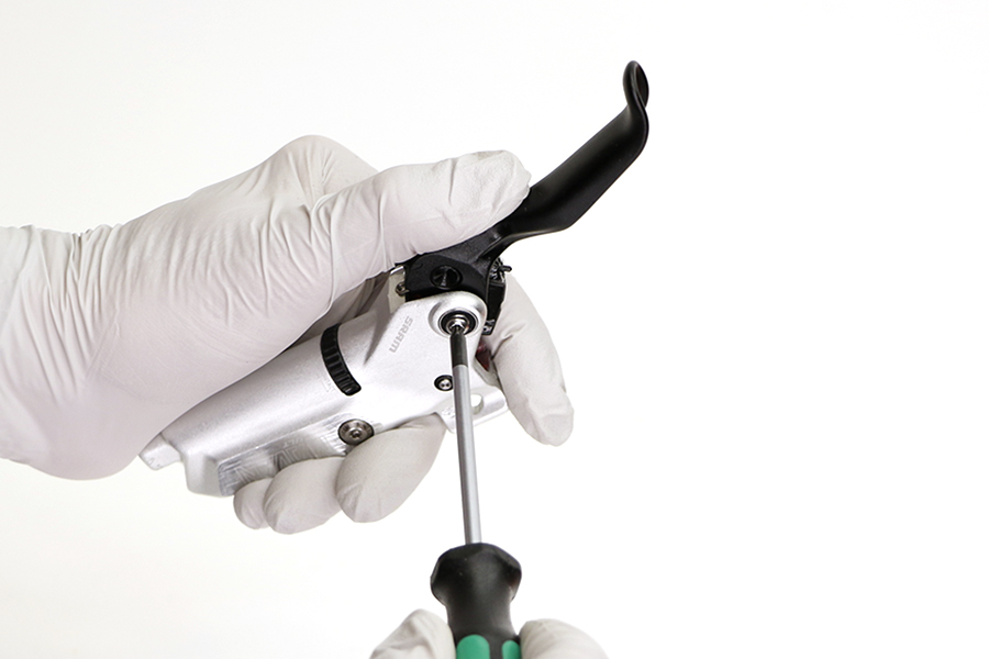
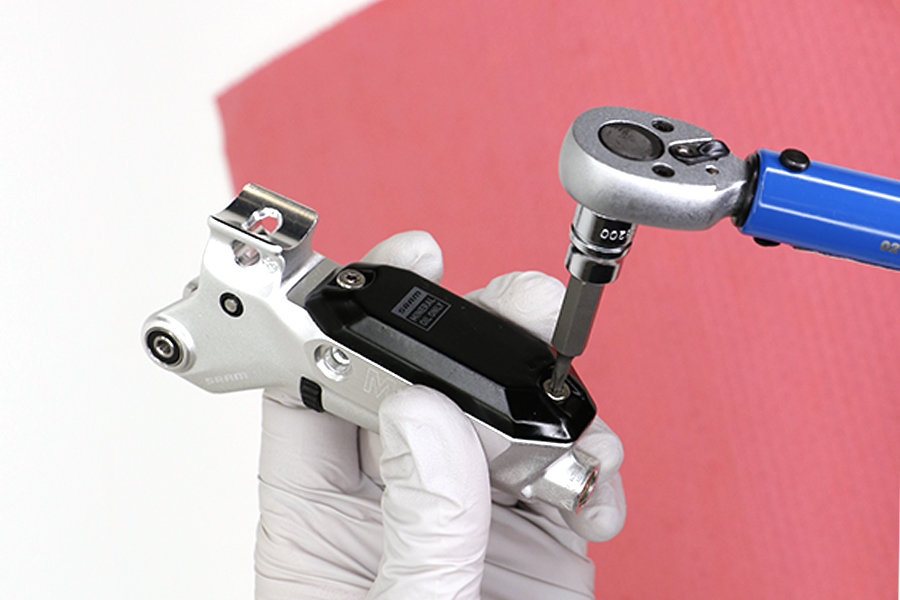
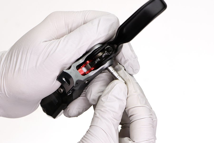
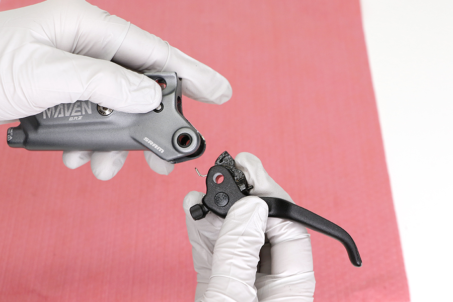
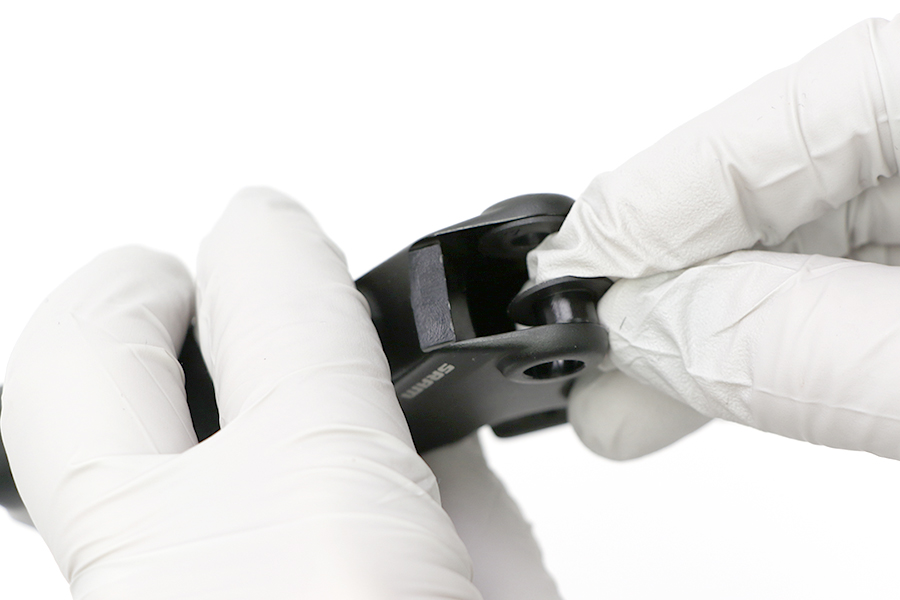
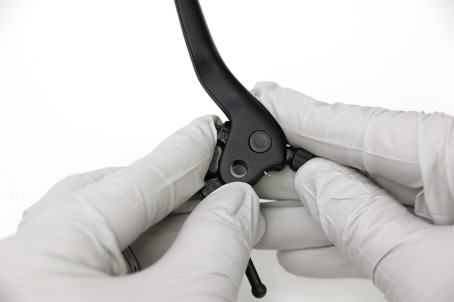
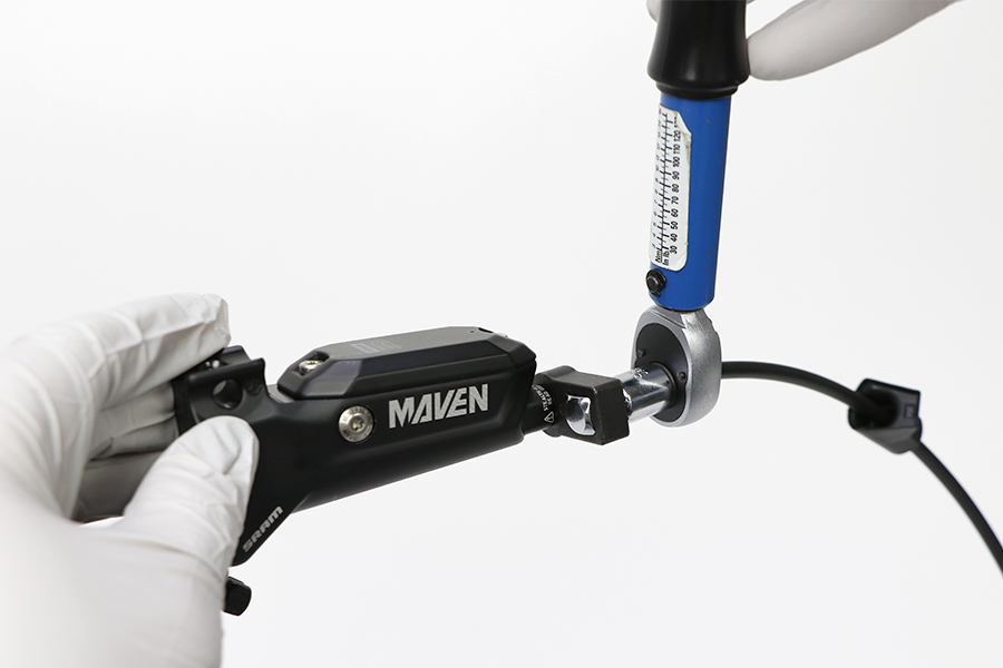
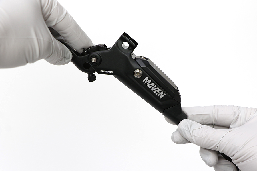
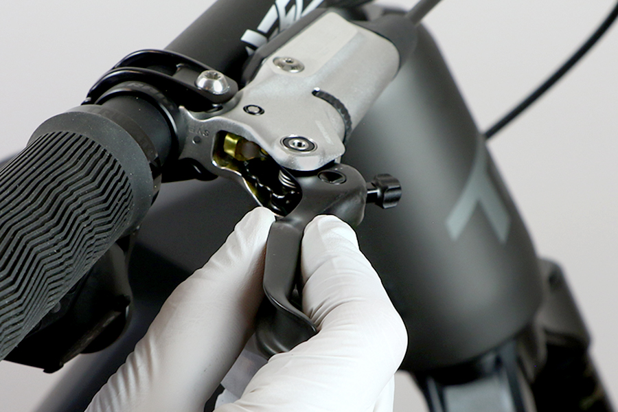
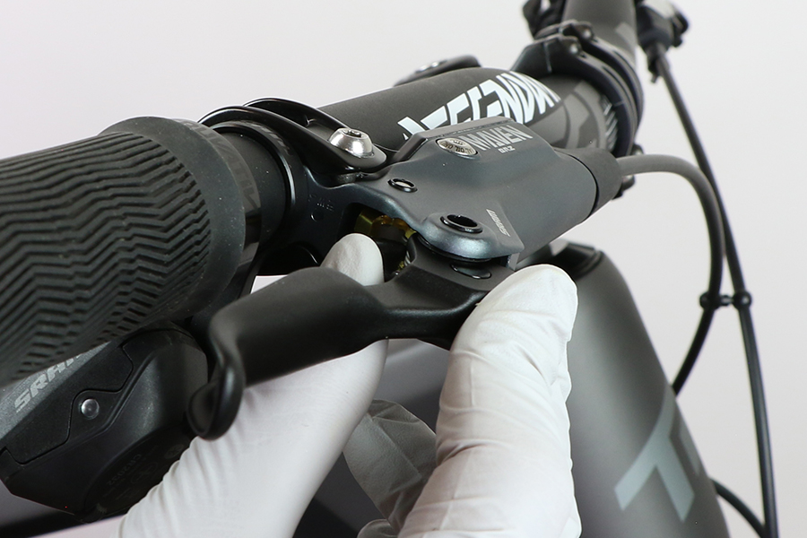
Remove the lever pivot bolt on each side of the lever.

Remove the lever blade assembly from the lever body.

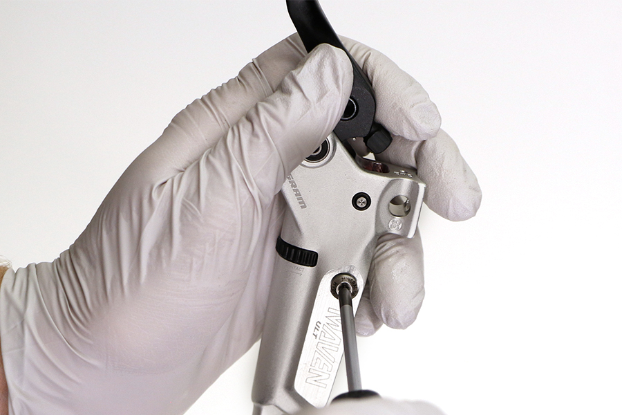
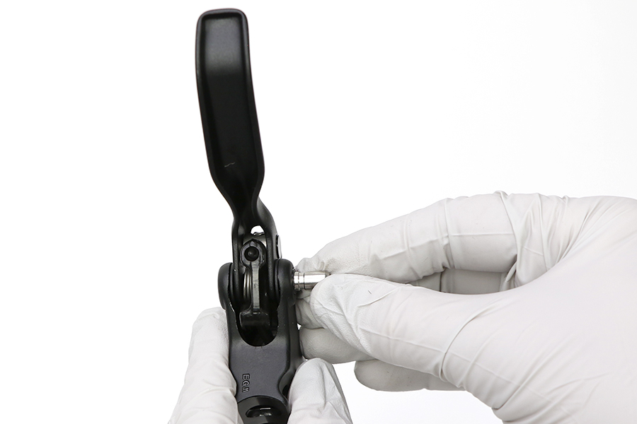
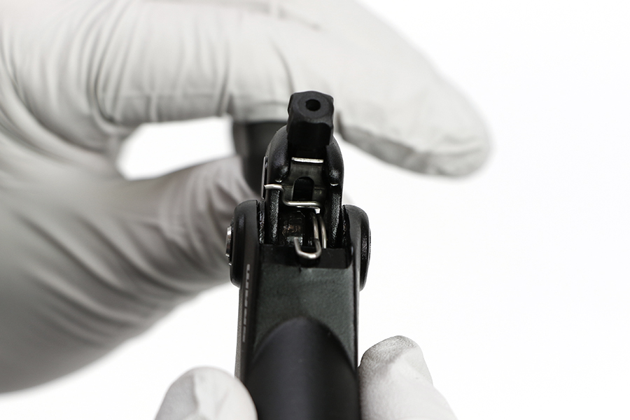
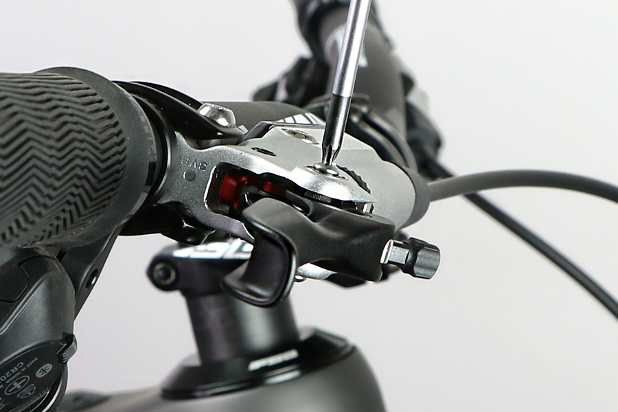
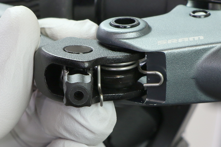
Turn the Contact Point Adjustment dial to the full out position.
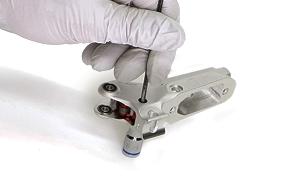
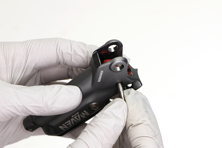
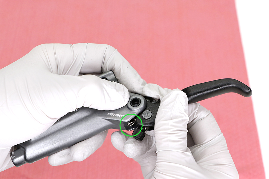
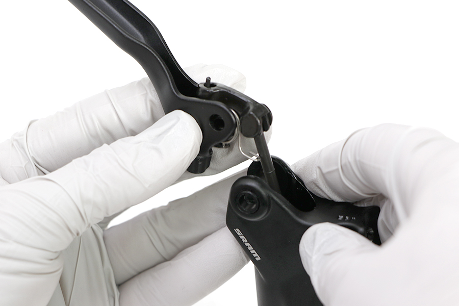
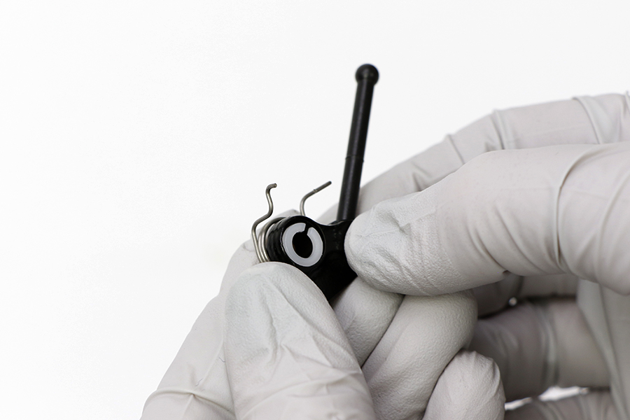
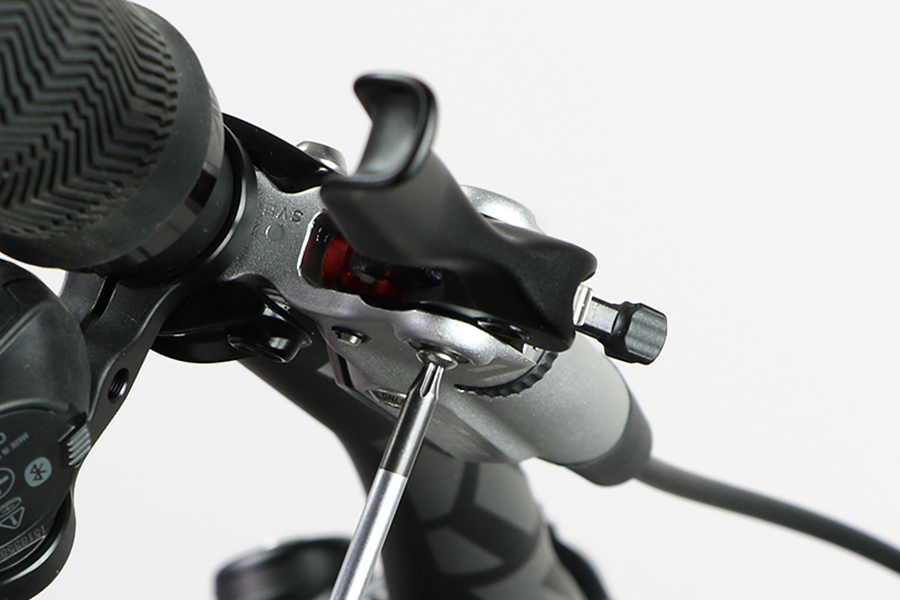
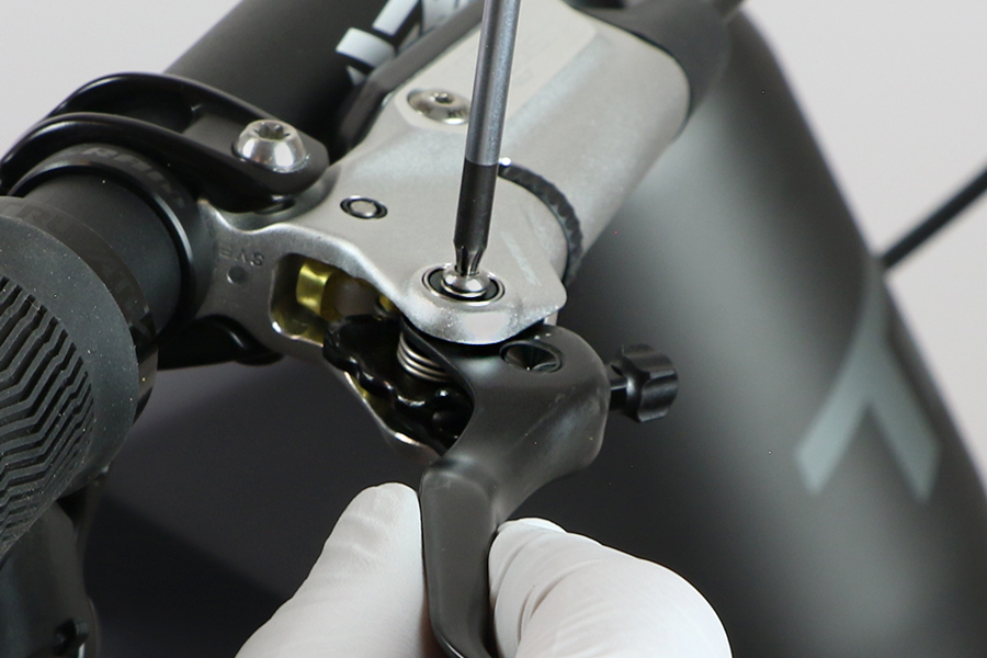
Rest a caliper pad retention bolt or T10 on top of the SwingLink pivot pin. While holding the bottom of the lever gently tap the caliper pad retention bolt with a plastic mallet to remove the SwingLink pivot pin from the lever body.
Set the SwingLink pivot pin aside.


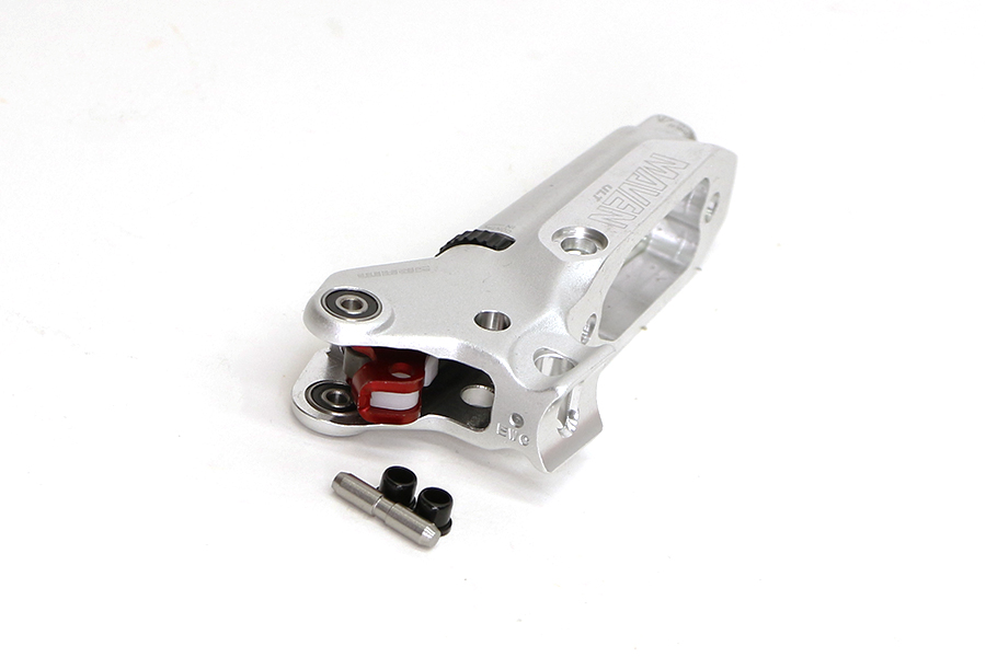
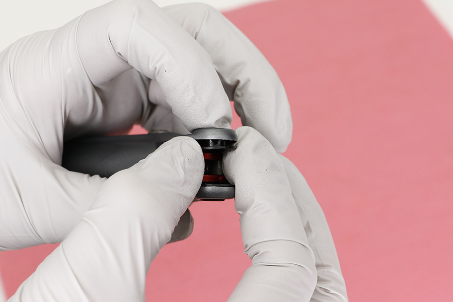
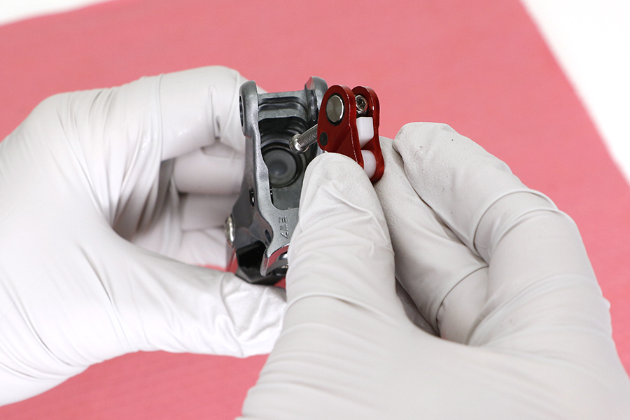
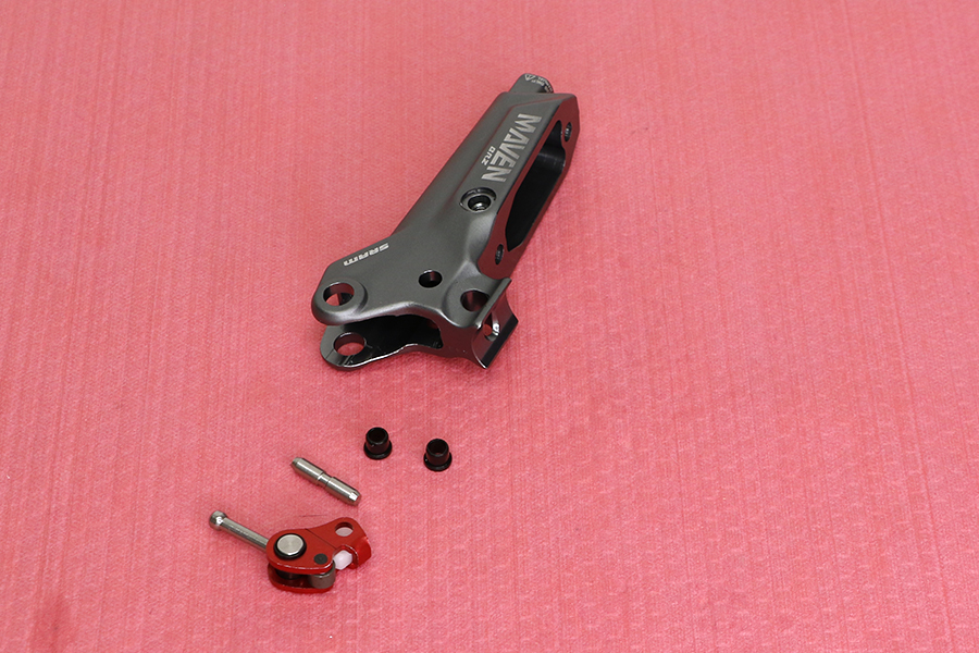
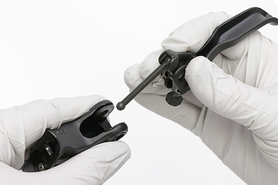
Remove the SwingLink. Remove and discard the SwingLink bushings.
Check the lever and SwingLink for damage. If the lever and SwingLink are undamaged, they may be kept as spares.
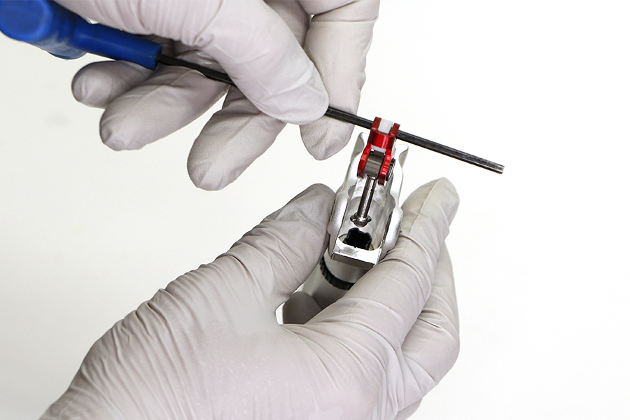
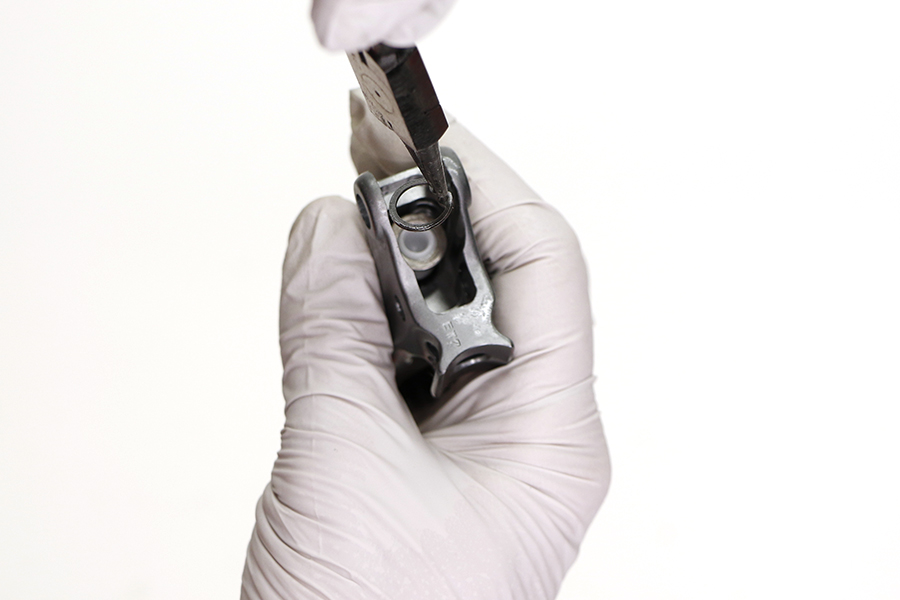
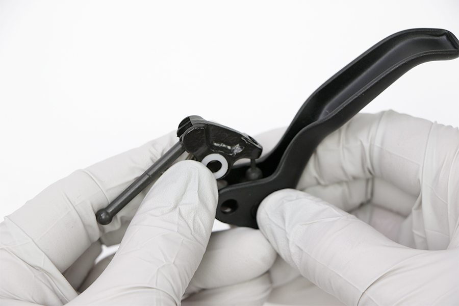
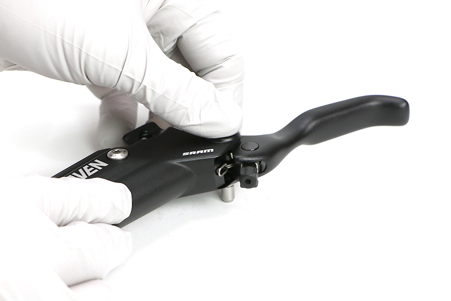
Install a new SwingLink bushing into each side of the lever.
If the SwingLink bushings fall out easily, apply a small amount of SRAM Hydraulic Brake grease to the bushings to help hold them in place.

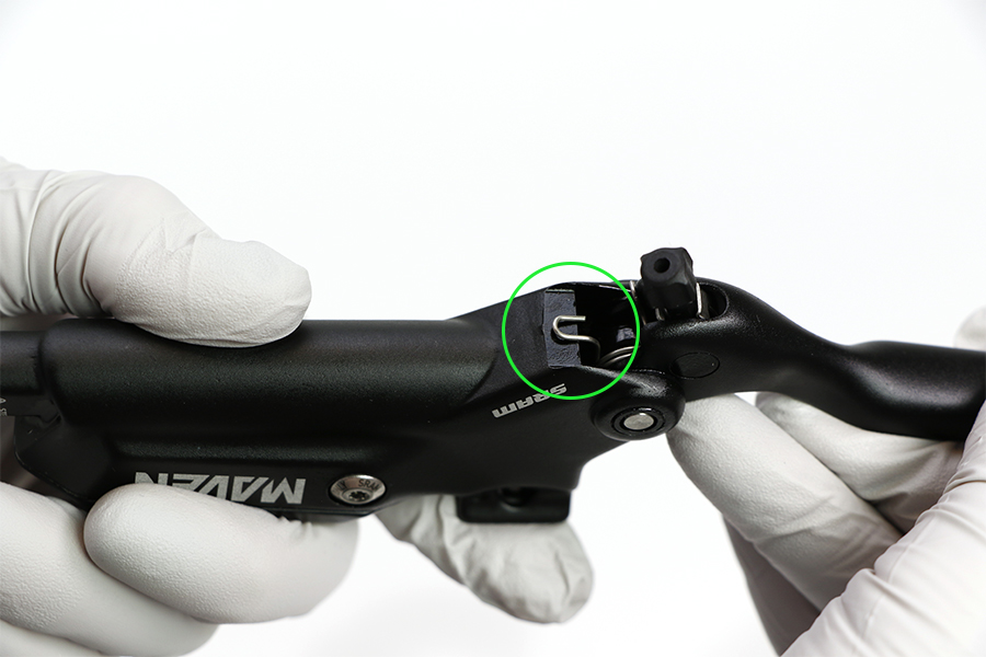
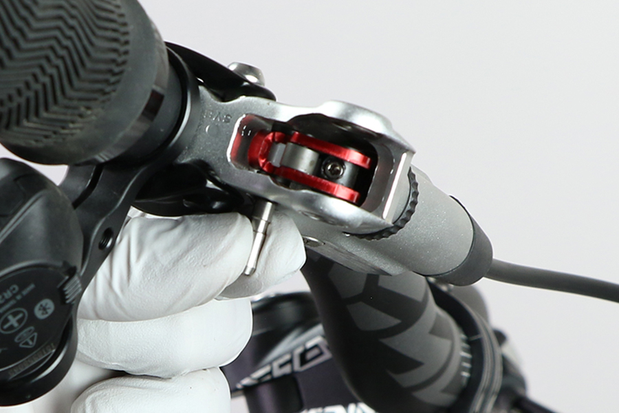
Use your fingers to rotate the SwingLink pushrod clockwise until the pushrod is fully extended. Do not over tighten.
Verify the Contact Point Adjustment dial is rotated to the full out position.


Install the SwingLink pushrod so the flared end is seated in the coupler sleeve.
It may be necessary to rotate the Contact Point Adjustment dial a 1/4 turn so the pushrod and coupler are seated evenly in the lever body.
Rotate the Contact Point Adjustment dial in and out to verify it moves easily. If there is resistance, repeat step 2 and 3.


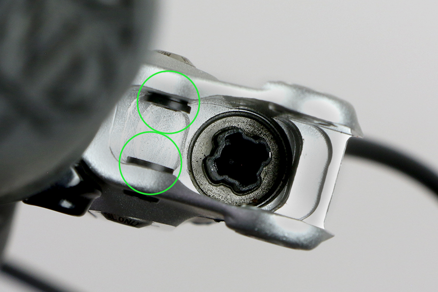
Align the holes of the SwingLink and the SwingLink bushings.
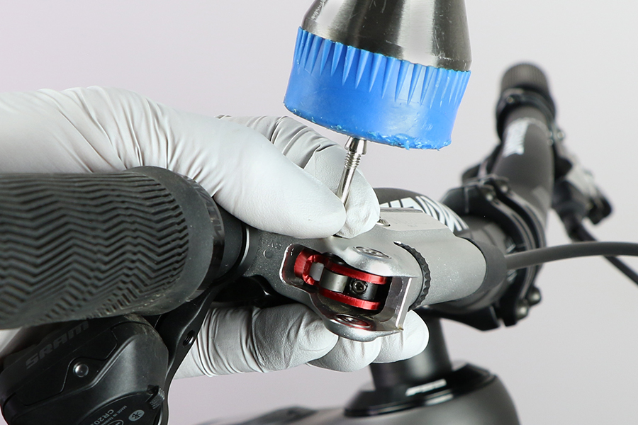
Use a plastic mallet to lightly tap the pivot pin into the hole until it is flush with the lever body.

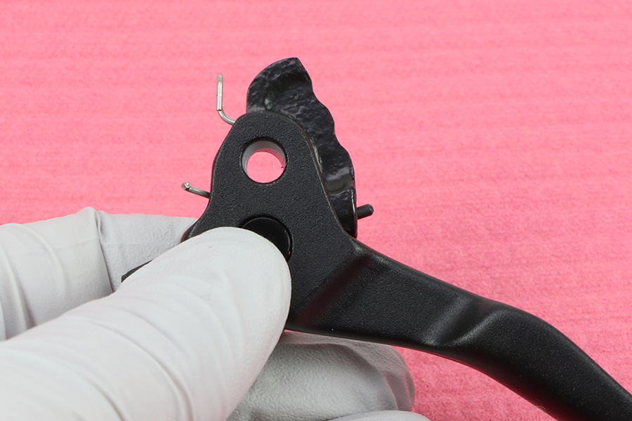
Adjust the long side of the spring so it is pressing on the surface of the lever body.
Align the pivot holes of the lever blade with the pivot holes in the lever body.
Install the lever blade.
Make sure the lever bias spring is seated properly in the lever. The short end of the spring must press against the lever blade, while the long end of the spring must press against the lever body. If the return spring is not seated properly, you will not be able to adjust the reach of the lever blade.
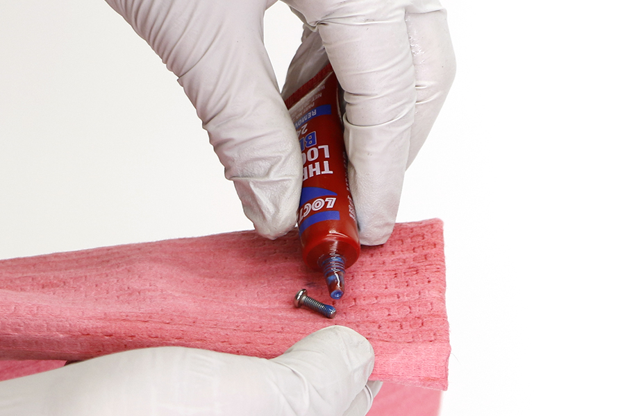
New pivot bolts come with threadlocker pre installed on the pivot bolts. If reusing the pivot bolts, clean the bolt threads and apply a small amount of Loctite Blue 242 or equivalent onto each pivot bolt.

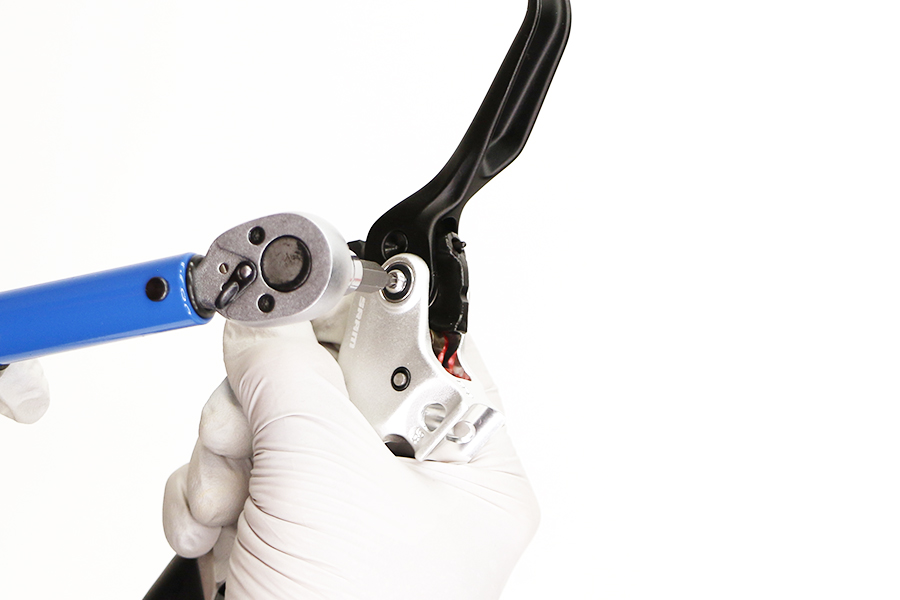
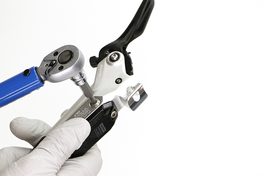
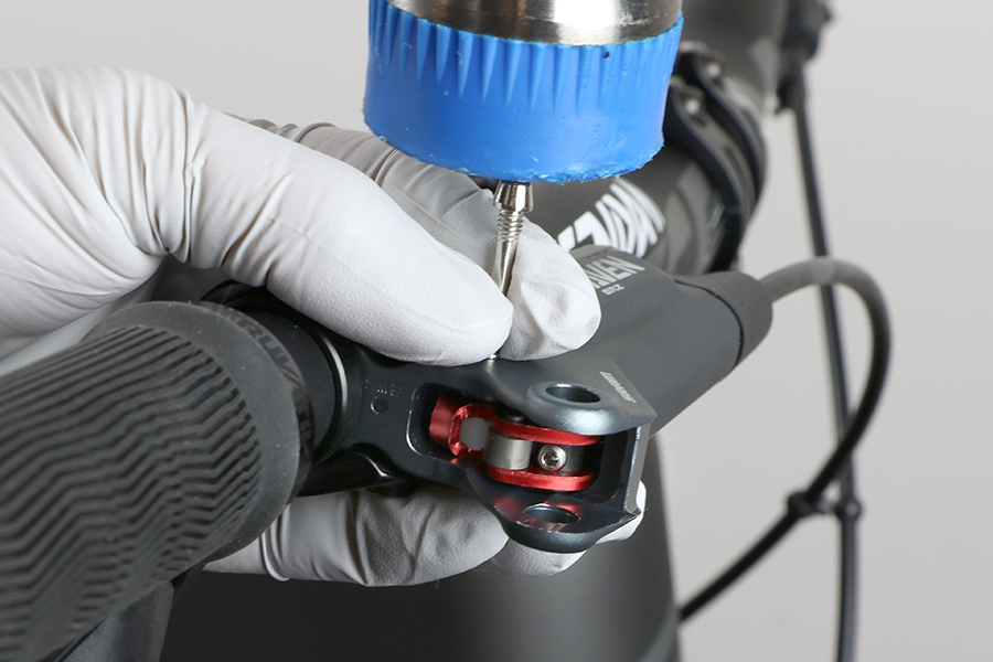
Thread each pivot bolt into the bearings on each side of the lever body.
Tighten each pivot bolt.
For Brake Lever Tuning Kit contents and details, consult the SRAM Spare Parts Catalog at the SRAM Service Site.


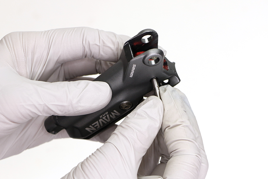
Rest a caliper pad retention bolt or T10 on top of the lever pivot pin. While holding the bottom of the lever, gently tap the caliper pad retention bolt with a plastic mallet to remove the lever pivot pin from the lever body.
Set the pivot pin aside.

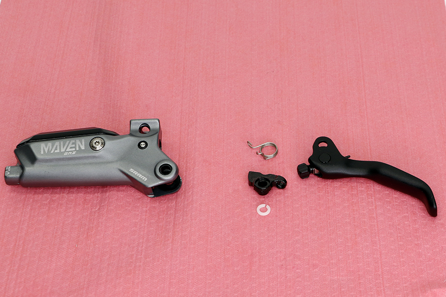
Remove the lever blade.
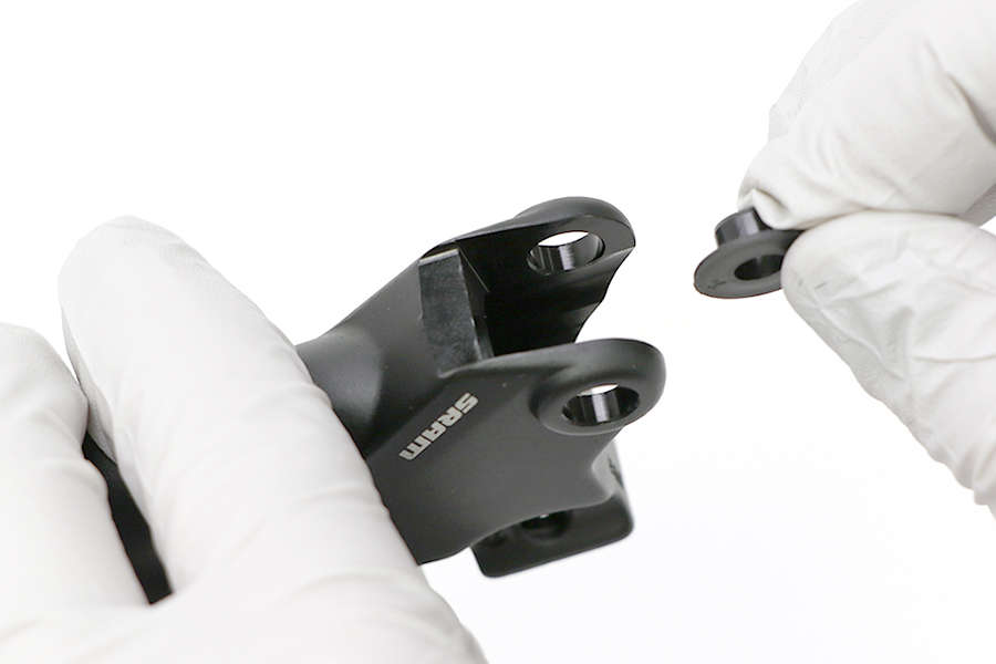
The lever assembly will separate into four pieces when removed from the lever body: SwingLink cam, lever bias spring, pivot clip, and blade assembly.

Remove and discard the pivot bushings.
Rest a caliper pad retention bolt or T10 on top of the SwingLink pivot pin. While holding the bottom of the lever gently tap the caliper pad retention bolt with a plastic mallet to remove the SwingLink pivot pin from the lever body.
Set the SwingLink pivot pin aside.

Remove the SwingLink.

Remove and discard the SwingLink bushings.
Install a new SwingLink bushing into each side of the lever.
If the SwingLink bushings fall out easily, apply a small amount of SRAM Hydraulic Brake grease to the bushings to help hold them in place.


Install the SwingLink pushrod so it is seated in the piston.
Align the holes of the SwingLink and the SwingLink bushings.
Use a plastic mallet to lightly tap the SwingLink pivot pin into the hole until it is flush with the lever body.
Install a new lever pivot bushing into each side of the lever.
If the lever pivot bushings fall out easily, apply a small amount of SRAM Hydraulic Brake grease to the bushings to help hold them in place.

Install the lever bias spring and pivot clip onto the SwingLink cam.
Hold the spring and pivot clip in place and install the hole on the SwingLink cam onto the reach adjust pin in the lever blade.
Adjust the long side of the spring so it is pressing on the surface of the lever body.
Align the holes in the cam and lever blade with the holes in the lever body.
Make sure the lever bias spring is seated properly in the lever. The short end of the spring must press against the lever blade, while the long end of the spring must press against the lever body. If the return spring is not seated properly, you will not be able to adjust the reach of the lever blade.

Install the pivot pin through the holes. Use a plastic mallet to lightly tap the pivot pin into the hole until it is flush with the lever body.
♻ For recycling and environmental compliance, please visit sram.com/en/company/about/environmental-policy-and-recycling.
Used mineral brake oil must be recycled or disposed of in accordance to local, state, and federal regulations. Never pour used brake oil or fluid down a sewage or drainage system or into the ground or body of water.
