General Safety

Safety First!
We care about YOU. Please, always wear your safety glasses and protective gloves when servicing SRAM products. Protect yourself! Wear your safety gear!












Safety First!
We care about YOU. Please, always wear your safety glasses and protective gloves when servicing SRAM products. Protect yourself! Wear your safety gear!
You must read and understand the Safety Instructions document included with your product before proceeding with the installation. Improperly installed components are extremely dangerous and could result in severe and/or fatal injuries. If you have any questions about the installation of these components, consult a qualified bicycle mechanic. This document is also available on www.sram.com.
COIN BATTERIES
INGESTION HAZARD
This product contains a button cell or coin battery.
DEATH or serious injury can occur if ingested.
A swallowed button cell or coin battery can cause INTERNAL CHEMICAL BURNS in as little as TWO HOURS.
KEEP new and used batteries OUT OF REACH OF CHILDREN.
SEEK IMMEDIATE MEDICAL ATTENTION if a battery is suspected to be swallowed or inserted inside any part of the body.


NO OBVIOUS SYMPTOMS
Unfortunately, it is not obvious when a button or coin battery is stuck in a child's esophagus. There are no specific symptoms associated with this.
The child might:
Cough, gag or drool a lot
Appear to have an upset stomach or a virus
Be sick
Point to their throat or stomach
Have pain in their abdomen, chest, or throat
Be tired or lethargic
Be quieter or more clingy than usual or otherwise “not themselves”
Lose their appetite or have a reduced appetite, not want to eat solid food, or be unable to eat solid food
These sorts of symptoms vary or fluctuate, with the pain increasing and then subsiding. A specific symptom to button and coin battery ingestion is vomiting fresh (bright red) blood. If the child does this seek immediate medical help. The lack of clear symptoms is why it is important to be vigilant with “flat” or spare button or coin batteries in the home and the products that contain them.
BATTERY AND BATTERY CHARGER
Lithium ion batteries are hazardous. Any failure to follow these safety instructions could damage the battery or charger which could cause fire, chemical burns, electrolyte leaks, and/or could lead to serious and/or fatal injuries. If the battery explodes, immediately call the fire department, cautiously remove any other batteries if possible, evacuate all persons from immediate area of fire, and use cold water to put out the fire.
1. Use only the SRAM-supplied charger for SRAM rechargeable batteries. Use of other chargers may cause the battery to overheat, catch fire, and/or explode. Review the User Manual for cord, charging port, and/or charging adapter specifications for use with your charger. Do not force discharge, recharge (coin batteries), disassemble, heat above manufacturer’s specified temperature rating, or incinerate your batteries. Doing so may result in injury due to venting, leakage or explosion resulting in chemical burns.
2. Replace rechargeable batteries with genuine SRAM rechargeable batteries only. Non-rechargeable batteries are not to be recharged.
3. Replace coin cell batteries used in SRAM components with a CR2032 or CR1632 battery only as defined in the user manual or on the product. Batteries must be 3V only. Ensure the batteries are installed correctly according to polarity (+ and -). Do not mix old and new batteries, different brands or types of batteries, such as alkaline, carbon-zinc, or rechargeable batteries.
4. Remove and immediately recycle or dispose of used batteries according to local regulations and keep away from children. Do NOT dispose of batteries in household trash or incinerate. Remove and immediately recycle or dispose of batteries from equipment not used for an extended period of time according to local regulations.
5. Do not use the battery outside of the temperature range specified in the user manual; avoid exposure to excessive heat or cold. Do not leave the battery in direct sunlight or in a vehicle.
6. Do not place the battery or charger in or near fire or in a place where static electricity occurs.
7. Do not modify or disassemble the battery or charger. Avoid dropping your battery or charger. Do not use a battery or charger that has been dropped or is damaged. Signs of damage include: discoloration, dents, cracks, punctures, or leakage.
8. Do not charge the battery in a damp or wet location. Avoid exposure to moisture and/or water during charging. For parts with a plug, do not insert or remove the plug while it is wet; otherwise it may cause electric shock. Make sure the plug is dry before inserting it.
9. Do not leave the battery in a charger or on equipment if it generates an odor and/or heat, changes color and/or shape, leaks electrolyte, or causes any other abnormality. If you notice any abnormalities, immediately remove the battery from the charger or equipment.
10. Do not leave a charging battery unattended. Do not leave the battery connected to the charger after charging is complete. Store the battery at room temperature with the battery cover on, if provided.
11. Do not allow metal, such as paper clips, coins, or keys, to come into contact with the battery terminals. Metal can damage the battery terminals and cause the battery to short-circuit.
12. Always completely secure the battery compartment. If the battery compartment does not close securely, stop using the product, remove the batteries, and keep them away from children.
Keep new and used batteries out of reach of children at all times. Batteries can be a choking hazard, and if swallowed can cause internal chemical burns in as little as two hours and lead to death. If you think batteries might have been swallowed or placed inside any part of the body, seek immediate medical attention. Even used batteries may cause severe injury or death. Call a local poison control center for treatment information.
SKIN IRRITANT
Under extreme usage or temperature conditions, battery leakage may occur. Do not allow leaked electrolyte to come into contact with eyes or skin. Immediately wash the affected area with clean water and seek medical advice.
Hands and gloves must be clean before handling the SRAM battery. Contact with sunscreen or hydrocarbon cleaners may cause the battery to crack.
This manual is a complete system installation guide, from unboxing each component to heading out for a ride. Eagle Transmission installation is unlike any system before, in which we prepare each component off the bike using details of your bike, loosely hang the components in place, then tighten the components in a specific sequence. Installation is easier than ever, but totally new, so please complete the installation and setup in the order described in the manual.
Do not begin a new section before completing the previous sections.
Your product's appearance may differ from the pictures contained in this publication.

Click on the icon at the top right corner of the screen to display the color legend and the complete list of tools and supplies for this manual in a scrollable dropdown list.
The colors and symbols featured in this manual correspond to specific actions or procedures. A detailed description for each color and symbol is contained in the dropdown.
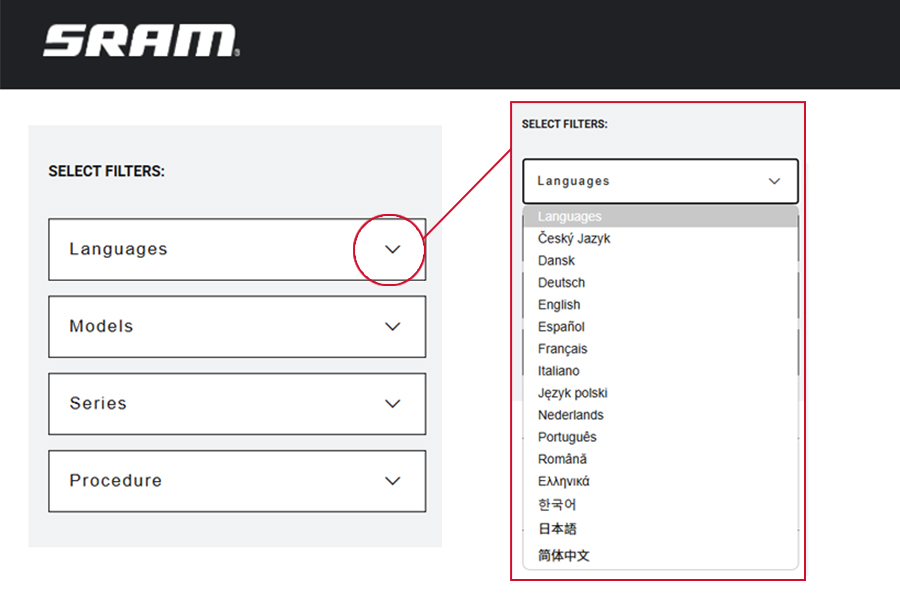
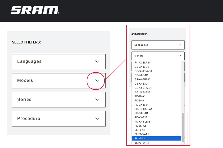
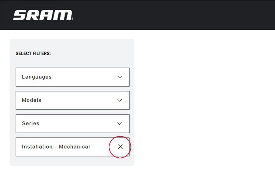
Use the dropdown lists in the SELECT FILTERS: window at the top left of the page to select the preferred language, product model code, and instructional content. Product instructional content filters will vary.
Language Filter: Select Language first. When a new language is selected, all other selected filters will reset.
All non-Language Filters: To reset a non-language filter, click on the X.
Product model code and specification details can be identified with the serial number on the product. Model codes can be used to identify the product type, series name, model name, and product version associated with the production model year. Product details can be used to identify spare parts, service kit, and lubricant compatibility.
Model Code example: RD-XX-E-B1
RD = Product Type - Rear Derailleur
XX = Platform/Series - XX
B1 = Version - (B - Second generation, 1 - first iteration)
To identify the model code, locate the serial number on the product and enter it into the Search by Model Name or Serial Number field at www.sram.com/service.
Your product's appearance may vary from those pictured in this manual.
Images and examples pictured are for conceptual purposes and may vary from product design, appearance, and performance.
Consult sram.com/service whenever a separate manual is referenced in this document.
Read the full warranty policy for your components at sram.com/en/service/warranty.
For information about trademarks used in this manual, visit sram.com/website-terms-of-use.
The SRAM DH Transmission derailleur is only compatible with a SRAM DH 7 Speed T-Type cassette. The system is compatible with most SRAM T-Type cranksets, chainrings, and chains with the exclusion of the chain, CN-TTYP-XXSL-A1. Consult the AXS Component Compatibility Map for compatibility information.
The XXSL chain, CN-TTYP-XXSL-A1, is not designed for use with Downhill (DH) or E-MTB / Pedelec systems.
For a list of approved chain tools, consult the Eagle, Flattop, and 11 Speed Chain Compatible Tools document.
This system is only compatible with bicycles that are designed with the Universal Derailleur Hanger (UDH) specification and comply with all required clearances. Visit www.sram.com to find more information on compatible frames.
SRAM components are designed for use only on bicycles that are pedal-powered or pedal-assisted (E-MTB/Pedelec).
SRAM Eagle Transmission systems have multi-shift functionality disabled by default. To enable the Multi-shift function, navigate to the system’s Drivetrain Settings within the SRAM AXS app.
The complete SRAM Warranty is available at www.sram.com.
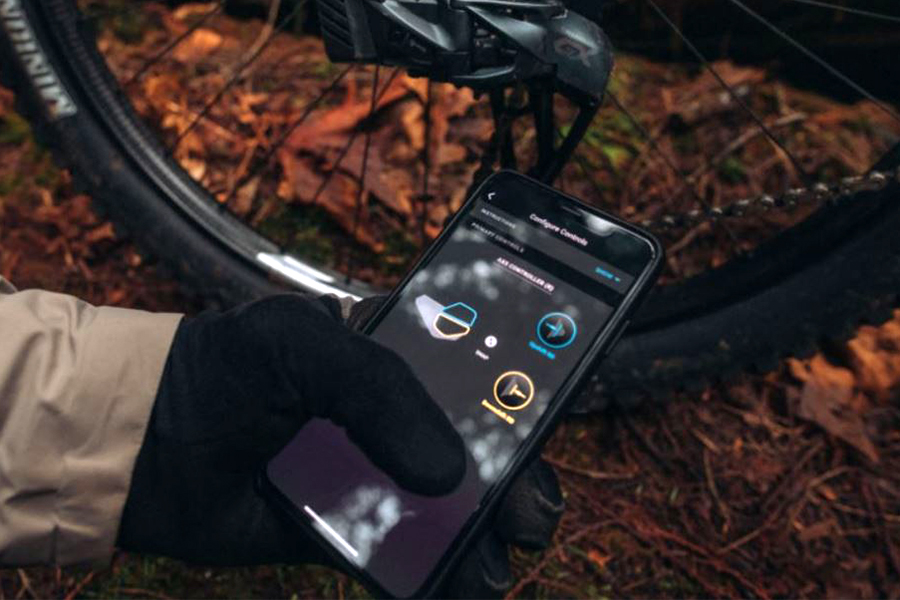
Download the SRAM AXS app, available for free in the app stores, to create your SRAM account, add your components, and customize your SRAM AXS experience.
Through the app, you will also be able to:
Connect your components via Bluetooth to the SRAM AXS app.
Build and personalize multiple bicycle profiles.
Monitor bicycle performance and readiness.
Customize component behavior to match your riding style.
Assign custom actions to your controls.
For component customization within the SRAM AXS app, all AXS components must be paired into a single system. Procedures for pairing multiple systems, such as an AXS seatpost and AXS drivetrain, can be found in the System Pairing section.
For optimal system performance and compatibility make sure you have installed the latest version of the SRAM AXS app and component firmware. Firmware updates are performed through the app.
Highly specialized tools and supplies are required for the replacement and maintenance of your SRAM components. We recommend that you have a qualified SRAM dealer work on your SRAM components.
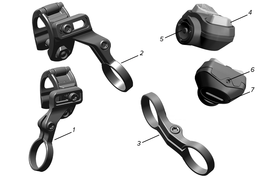
1. Left MatchMaker X (MMX) Bridge | 4. Controller Buttons | 7. Battery Cover |
2. Right MatchMaker X (MMX) Bridge | 5. AXS Button (Pairing) | |
3. Left and Right Infinity Clamp | 6. LED Indicator |
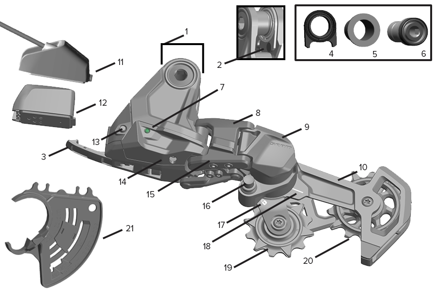
1. Full Mount* | 8. Upper Parallelogram* | 15. Lower Parallelogram* |
2. Knurled Ring Stop | 9. P-Knuckle | 16. Cage Mode Button |
3. Battery Latch* | 10. Cage and Damper Assembly* | 17. Cage Lock Icon |
4. Knurled Ring | 11. SRAM Extension Cord | 18. Key Line |
5. Bushing Frame Insert | 12. SRAM Battery | 19. Upper Pulley* |
6. Mount Bolt | 13. AXS Button (Pairing, Battery Status) | 20. Lower Pulley* |
7. LED Indicator | 14. Skid Plate* | 21. DH Chain Gauge tool |
*Replaceable part; see spare part catalog.
This manual is a complete system installation guide, from installing each component to heading out for a ride. Complete the installation and setup in the order described in the manual. Do not begin a new section before completing the previous sections.
Your product's appearance may differ from the images contained in this publication.
AXS components are only compatible with other AXS components. Consult the AXS Component Compatibility Map for compatibility information.
Consult www.sram.com/service whenever a separate manual is referenced in this document.
The complete SRAM DH Transmission System installation consists of the following steps:
1. SRAM Battery Charging and Installation
2. Cassette Installation
3. DUB Bottom Bracket Installation
4. DUB Crankset Installation
5. AXS Controller Installation
6. UDH Removal
7. DH Transmission Derailleur Installation
8. T-Type Chain Sizing and Installation
Previously installed components may be used in a DH Transmission System if they are compatible with SRAM DH Transmission and have been correctly installed.
Hands and gloves must be clean before handling the SRAM battery. Contact with sunscreen or hydrocarbon cleaners may cause the battery to crack.
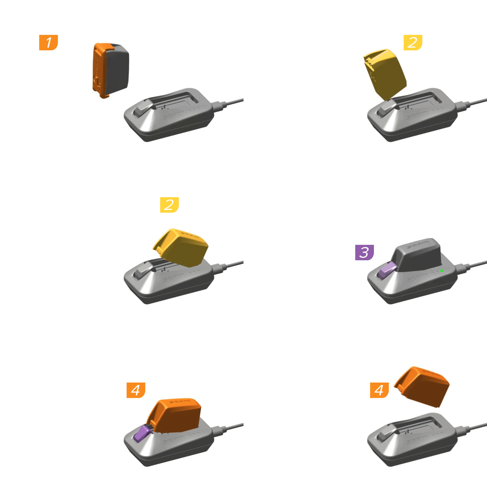
1. Remove the battery cover from the battery.
2. Install the battery into the charger. The LED on the charger will turn yellow while charging, and turn green when the battery is fully charged.
3. Press down on the release button.
4. Remove the battery from the charger.
Consult the SRAM Battery and Charger User Manual for charging instructions, battery maintenance, and travel guidelines.
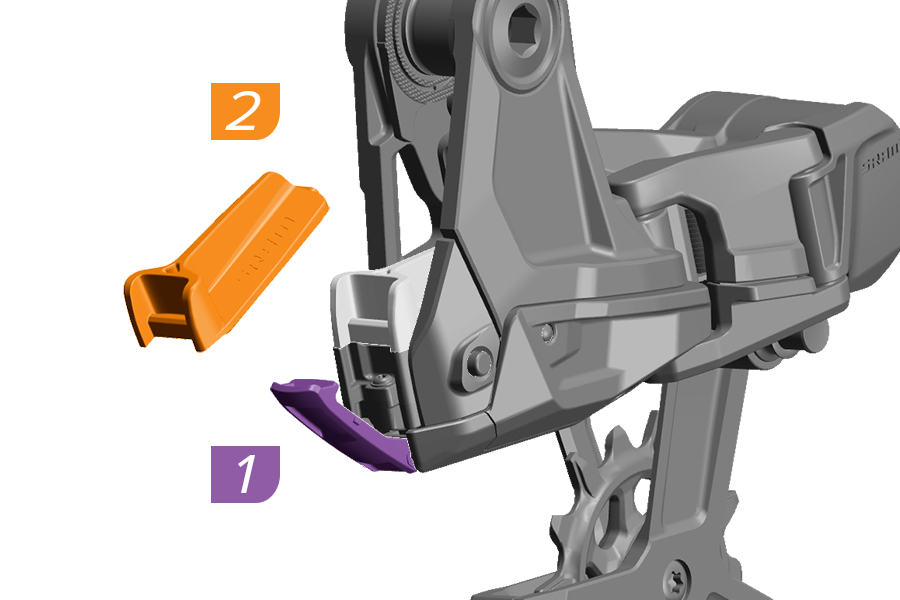
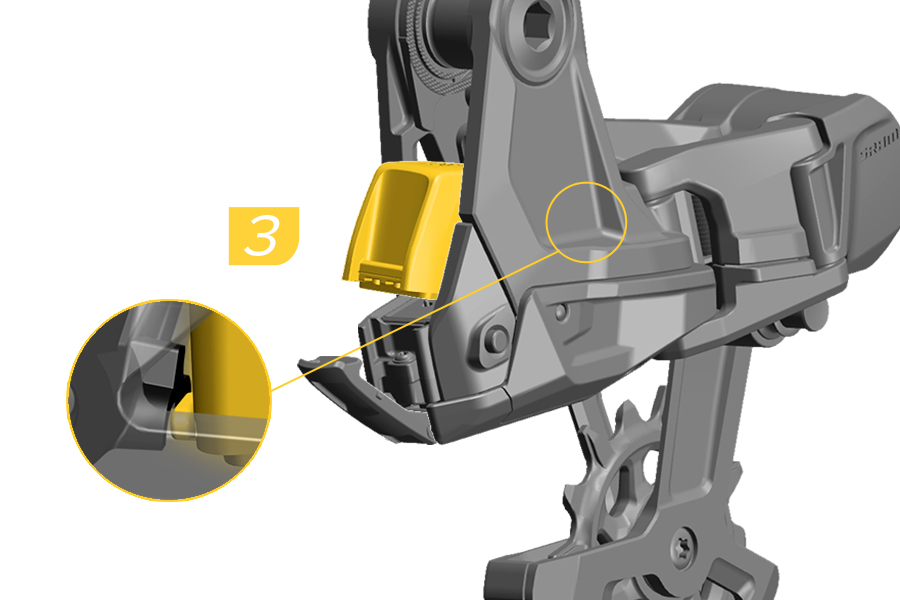
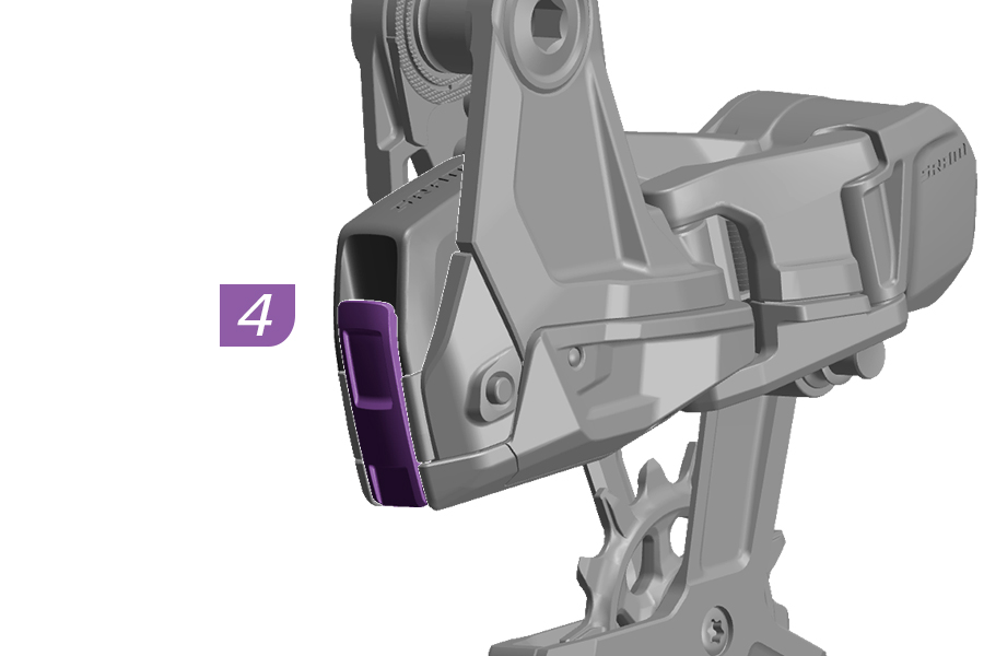
1. Open the battery latch.
2. Remove the battery block.
The battery block is installed to protect the electronic terminals.
3. Insert the fully charged SRAM battery into the derailleur.
4. Close the battery latch.
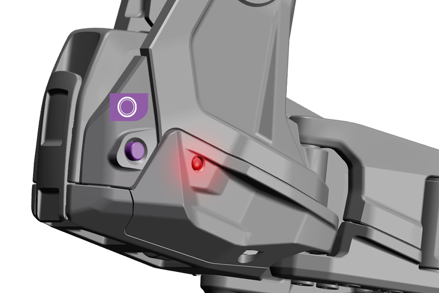
When installed correctly, the latch will snap into place and the LED will flash green once.
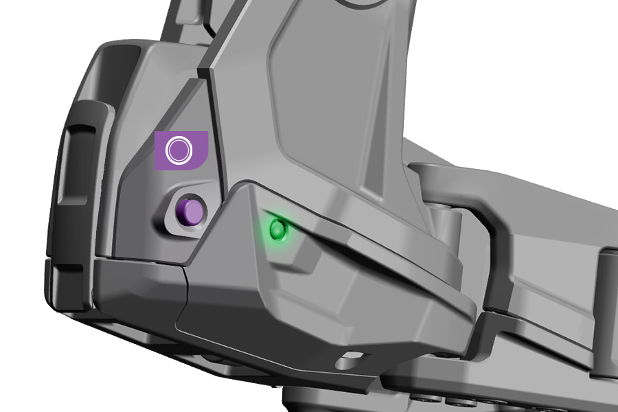
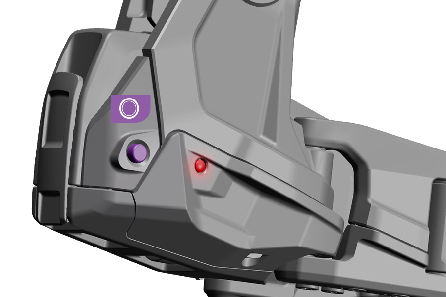
The AXS component LED indicators illuminate when the component AXS button is pressed and when a shift is performed. The color of the LED indicates the battery charge level.
During use, if an AXS component has a blinking red LED, the battery must be recharged or replaced.
The LED on the transmission will blink red and green when a shift has been rejected. Shifts can be rejected when the temperature is below -15 °C (5 °F).
Battery levels can also be checked in the SRAM AXS app.
You must use a SRAM DH 7 Speed T-Type cassette.
SLIM cassettes are not interchangeable with standard XD cassettes.
There is no cross-compatibility between XD and XD SLIM cassettes and driver bodies. Use the cassette designed for your driver body.
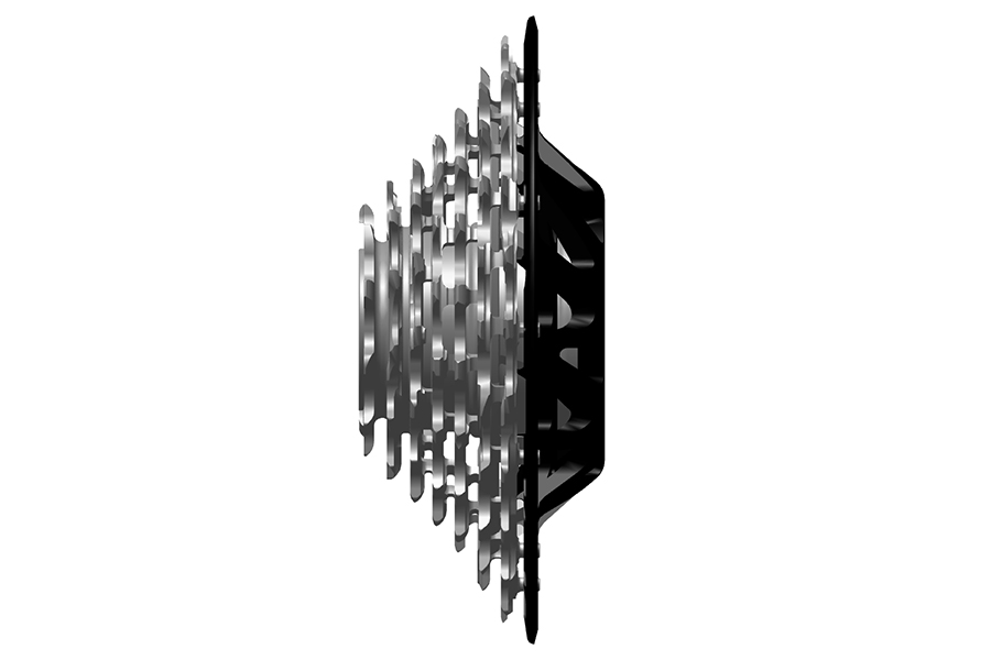
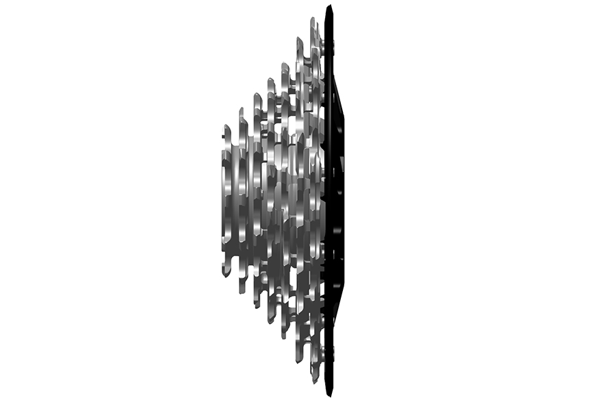
The XD SLIM cassette can be identified with an "S" in the model code (CS-XS-797S-A1) and a slim spoke guard. SLIM cassettes are not interchangeable with standard XD cassettes.
SRAM XD SLIM cassettes are compatible only with the SRAM XD SLIM driver body standard.
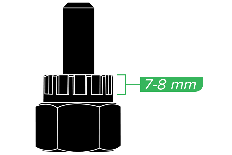
Cassette lockring tool splines must fully engage the cassette lockring or locktube (XD). Splines must be between 7 and 8 mm in length for XD, XD SLIM, and XDR cassettes.
Use a tool with a guide pin to prevent damage to the components. If there is lateral play or movement in the cassette after tightening it, contact your SRAM dealer.
SRAM XD cassettes are compatible with the SRAM XD driver body and with the XDR driver body using a 1.85 mm spacer.
SRAM XDR cassettes are compatible only with the SRAM XDR driver body standard.
SRAM XD SLIM cassettes are compatible only with the SRAM XD SLIM driver body standard.
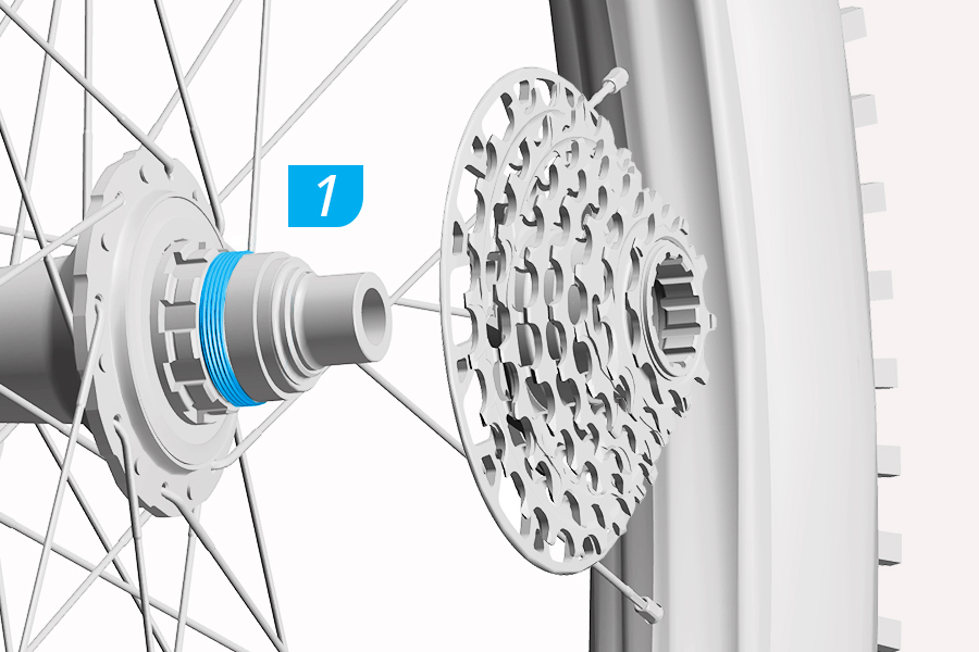
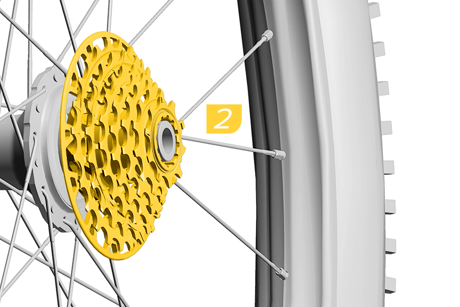
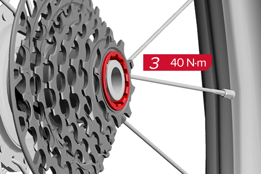
1. Apply grease to the driver body threads.
2. Install the cassette onto the driver body until it is fully seated and the splines are engaged. Use a tool with a guide pin to tighten the cassette while applying inward pressure to the cassette.
3. Use a torque wrench to tighten the cassette.
Grease is critical to prevent the cassette from seizing onto the driver body. Make sure the hub driver body and cassette interface are free of dirt and debris.
If the cassette becomes difficult to rotate after a few turns, the cassette may be cross-threaded. Loosen the cassette and re-thread it onto the driver body.
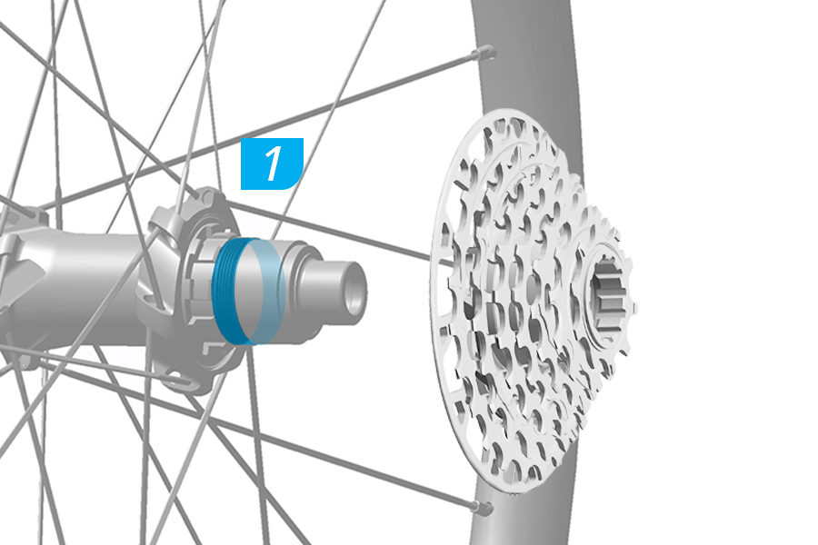
.jpg)
.jpg)
1. Apply grease to the driver body threads.
2. Install the cassette onto the driver body until it is fully seated and the splines are engaged. Use a tool with a guide pin to tighten the cassette while applying inward pressure to the cassette.
3. Use a torque wrench to tighten the cassette.
Grease is critical to prevent the cassette from seizing onto the driver body. Make sure the hub driver body and cassette interface are free of dirt and debris.
If the cassette becomes difficult to rotate after a few turns, the cassette may be cross-threaded. Loosen the cassette and re-thread it onto the driver body.
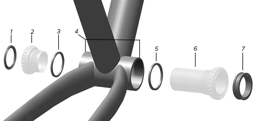
1. Outer left, non-drive side spacer | 4. Frame shell width | 7. Outer right, drive side spacer |
2. Left side cup | 5. Inner right, drive side spacer | |
3. Inner left, non-drive side spacer | 6. Right side cup and center tube |
Frame Shell Interface and Width (mm) | Crankset | Outer Left Spacer (mm) | Inner Left Spacer (mm) | Inner Right Spacer (mm) | Outer Right Spacer (mm) |
|---|---|---|---|---|---|
BSA (68) | MTB | - | 2.5 | 2.5 | 4.5 |
BSA (68) | MTB WIDE | 3 | 2.5 | 2.5 | 7.5 |
BSA (73) | MTB | - | - | - | 4.5 |
BSA (73) | MTB WIDE | 3 | - | - | 7.5 |
BSA (73) | Super Boost + | 4.5 | - | - | 9 |
BSA (73 Ai) | MTB Ai | 2.5 | 2.5 | - | 10.5 |
BSA (73 with Chain Guide) | MTB | - | - | Chain Guide | 2 |
BSA (73 with Chain Guide) | MTB Wide | 3 | - | Chain Guide | 5 |
BSA (73 with Chain Guide) | Super Boost + | 4.5 | - | Chain Guide | 6.5 |
BSA (83) | DH | - | 2.5 | 2.5 | 4.5 |
BSA (83 Ai) | MTB Ai | - | - | - | 5.5 |
BSA (100) | Fat | 2 | 2.5 | 2.5 | 6 |
PressFit (89.5) | MTB | - | - | - | 4.5 |
PressFit (89.5) | MTB Wide | 3 | - | - | 7.5 |
PressFit (92) | MTB | - | - | - | 2 |
PressFit (92) | MTB Wide | 3 | - | - | 5 |
PressFit (92) | Super Boost + | 4.5 | - | - | 6.5 |
PressFit (104.5) | DH | - | - | - | 4.5 |
PressFit (107) | DH | - | - | - | 2 |
PressFit (121) | Fat | 2 | - | - | 6 |
PressFit 30 (73) | MTB | - | - | - | 4.5 |
PressFit 30 (73) | MTB Wide | 3 | - | - | 7.5 |
PressFit 30 (83) | MTB Wide | 3 | - | - | 7.5 |
PressFit 30 (83) | DH* | 3 | - | - | 6.5 |
PressFit 30 (83 Ai) | MTB Wide | 3 | - | - | 7.5 |
PressFit 30 (83 Ai) | MTB Ai | - | - | - | 5.5 |
PressFit 30 (100) | Fat | 4.5 | - | - | 8.5 |
BB30 (73) | MTB | - | - | - | 4.5 |
BB30 (73) | MTB Wide | 3 | - | - | 7.5 |
BB30 (83 Ai) | MTB Ai | - | - | - | 5.5 |
*PressFit 30 DH bottom brackets must use the crankset with the words DUB DH BSA/PF30/PF marked on the spindle.
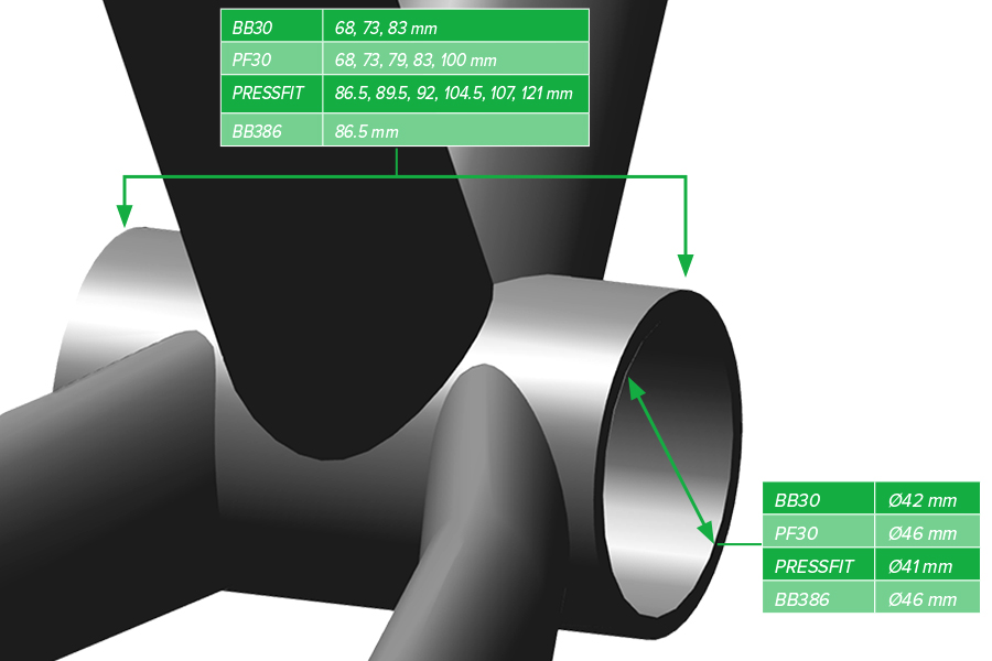
SRAM DUB BB30 bottom brackets are compatible with frame shells with an inner diameter of 42 mm.
DUB PressFit 30 and BB386 bottom brackets are compatible with frame shells with an inner diameter of 46 mm.
DUB PressFit bottom brackets are compatible with frame shells with an inner diameter of 41 mm.
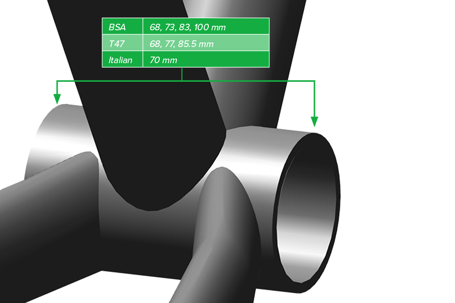
SRAM DUB BSA bottom brackets are compatible with frame shells with English threads.
SRAM DUB T47 bottom brackets are compatible with frame shells with M47 x 1 threads.
SRAM DUB Italian bottom brackets are compatible with frame shells with 36 mm x 24 tpi threads.
Spray isopropyl alcohol on the bottom bracket shell and clean it. The shell should be free of dirt, paint, grease, and metal burrs. For best results, have your frame faced by a professional bicycle mechanic.
Consult your frame manufacturer to confirm the bottom bracket is compatible with the bottom bracket shell in your frame.
Removing the center tube from the bottom bracket to accommodate internal brake hose routing is not recommended, and may shorten the lifespan of the bottom bracket.
Your product's appearance may differ from the pictures contained in this publication.
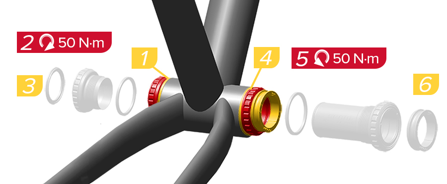
1. Install the inner non-drive side spacer if indicated by the chart.
2. Use a 12-notch external bottom bracket tool to tighten the non-drive side cup into the frame.
3. Install the left external spacer as indicated by the spacer chart.
4. Install the inner drive side spacer if indicated by the chart.
5. Use a 12-notch external bottom bracket tool to tighten the drive side cup into the frame.
6. Install the right external spacer as indicated by the spacer chart.
The right side cup for BSA threads is reverse threaded.
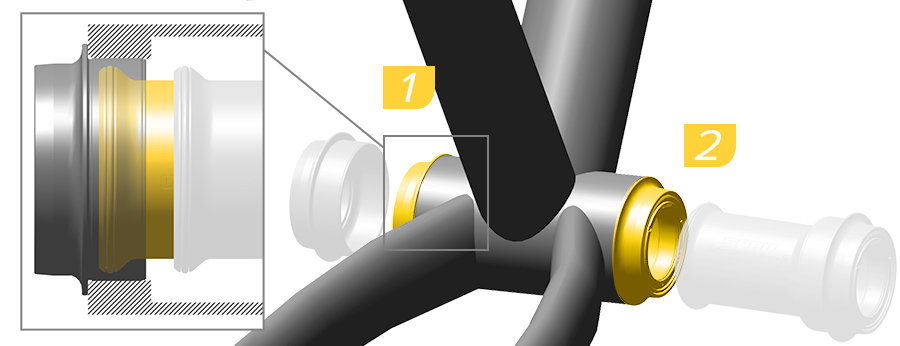
1. Use a bottom bracket bearing press tool or a headset press to install the left side cup into the non-drive side of the frame according to the tool manufacturer's instructions.
2. Repeat the installation with the right side cup and center tube into the drive side of the frame.
Make sure to guide the center tube parallel through the bottom bracket shell. The center tube should not contact the frame or any cable(s).
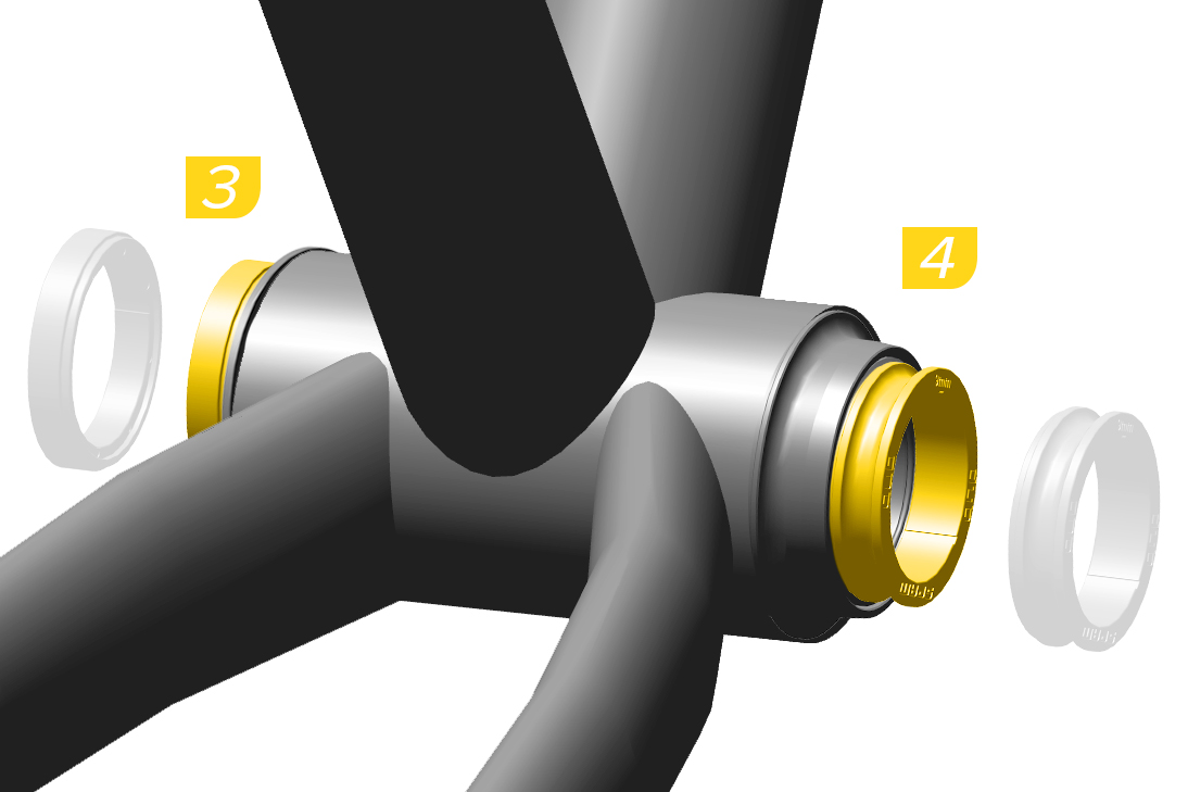
3-4. Install the spacer(s) according to the Crankset and Bottom Bracket table.
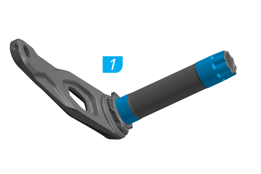
1. Apply grease to the indicated areas on the spindle.
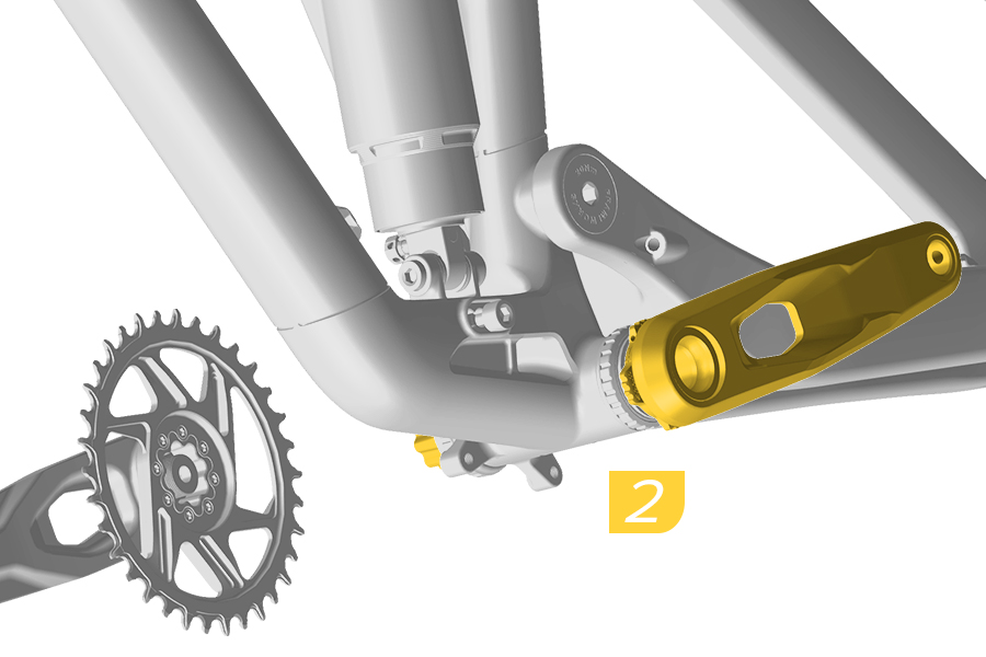
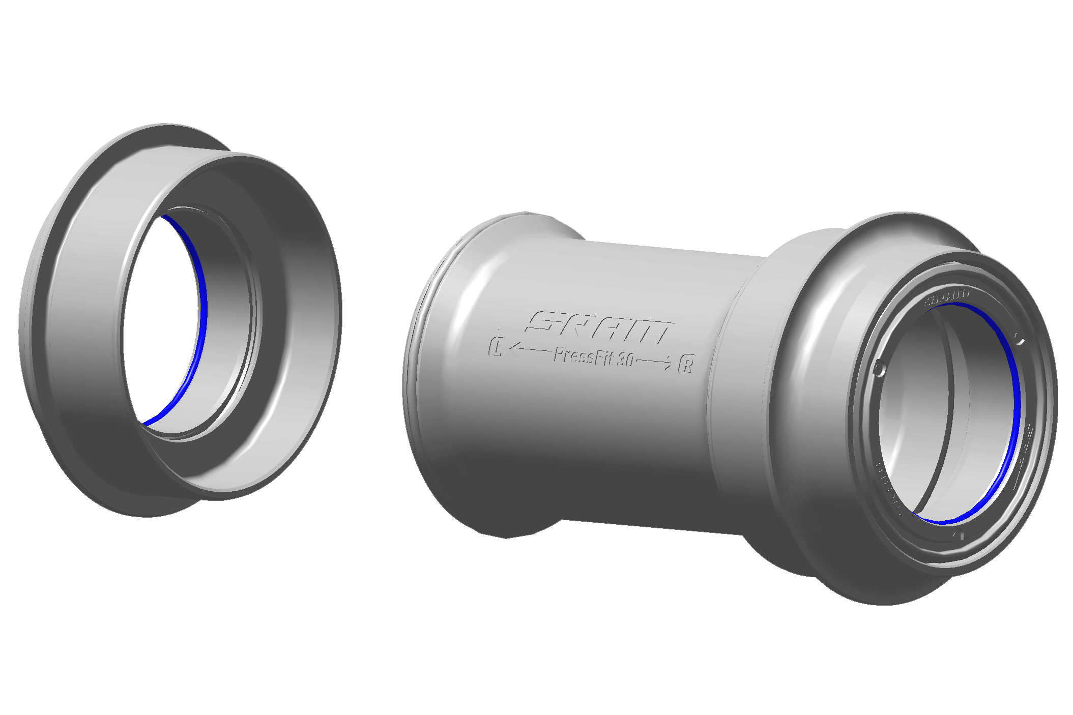
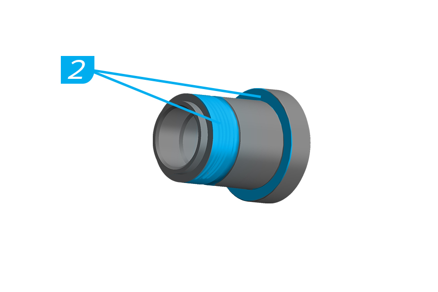
2. Install the non-drive side crankarm and spindle into the bottom bracket. Make sure the blue o-rings remain installed in the gland in the left and right bottom bracket cups during spindle installation.
A blue o-ring out of the gland could result in excessive friction during installation. On the drive side, the o-ring would be on the spindle. To confirm the drive side o-ring is in place you must remove the crank.
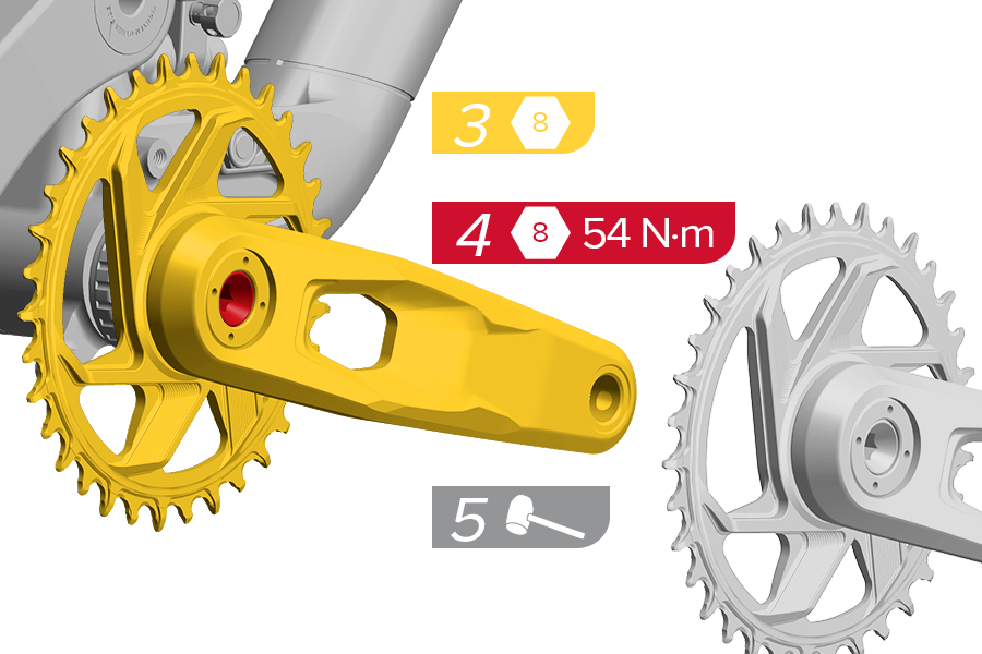
3. Install the drive-side crankarm onto the spindle.
4. Use a torque wrench with an 8 mm hex bit socket to tighten the crank arm bolt to 54 N·m (478 in-lb).
5. Use a rubber or plastic mallet to tap the drive side crank arm until it is fully seated.
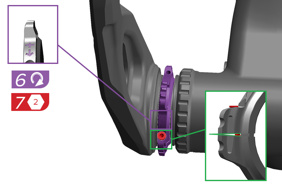
6. Remove play from the system by turning the preload adjuster in the + direction until it stops or makes contact with the bearing shield.
7. Use a 2 mm hex wrench to tighten the bolt until the adjuster edges touch.
Do not use a ball-end style hex wrench to tighten the preload adjuster.
Do not overtighten the preload adjuster as this could damage the bearing. Do not overtighten the bolt. It is okay if there is a gap in the adjuster, as long as the top edges touch.
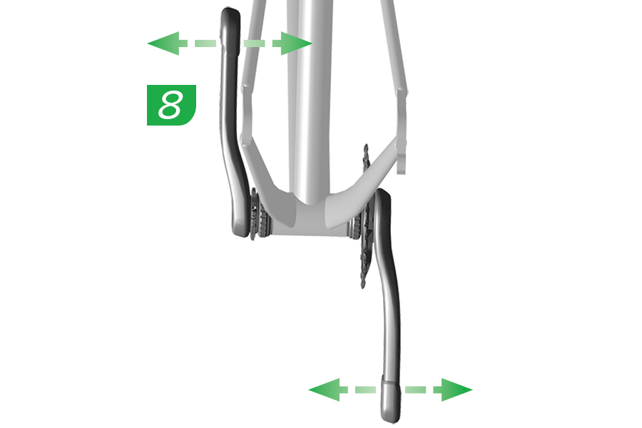
8. Check the crankset for play by rocking the crankarms back and forth.
If there is play in the crankset, remove the crankarms and apply additional grease to the spindle. Turn the preload adjuster in the opposite direction of the + sign until it stops. Repeat the installation procedure until play is eliminated.
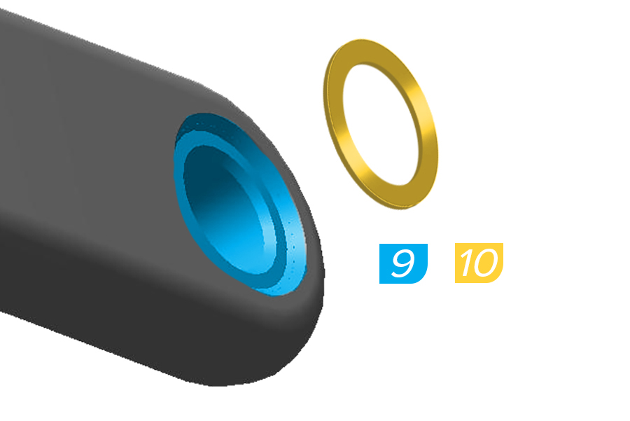
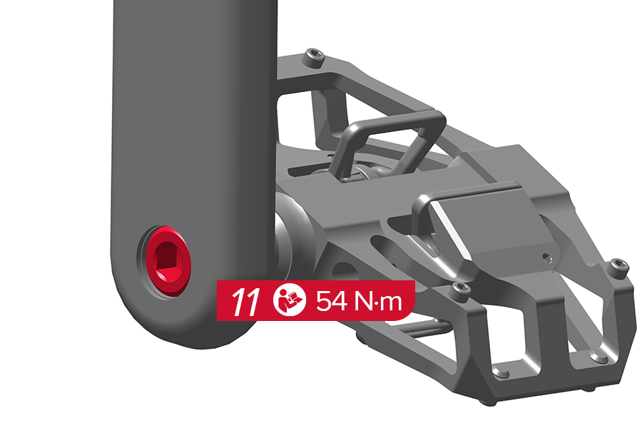
9. Apply grease to the crank arm pedal threads.
10. Install the washer between the crank arm and pedal.
11. Tighten the pedal shaft to 54 N·m (477 in-lb) unless otherwise specified by the pedal manufacturer.
The non-drive side pedal bore is reverse threaded.
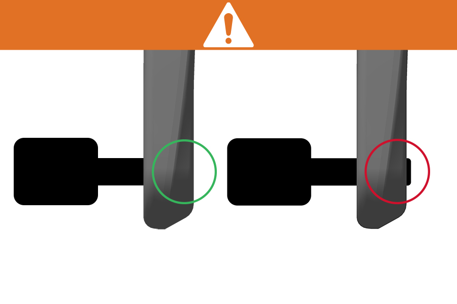
Make sure the pedal shaft threads do not extend past the back of the crankarm. Do not use the pedal if the shaft is exposed. This could interfere with the frame or chain and result in a crash.
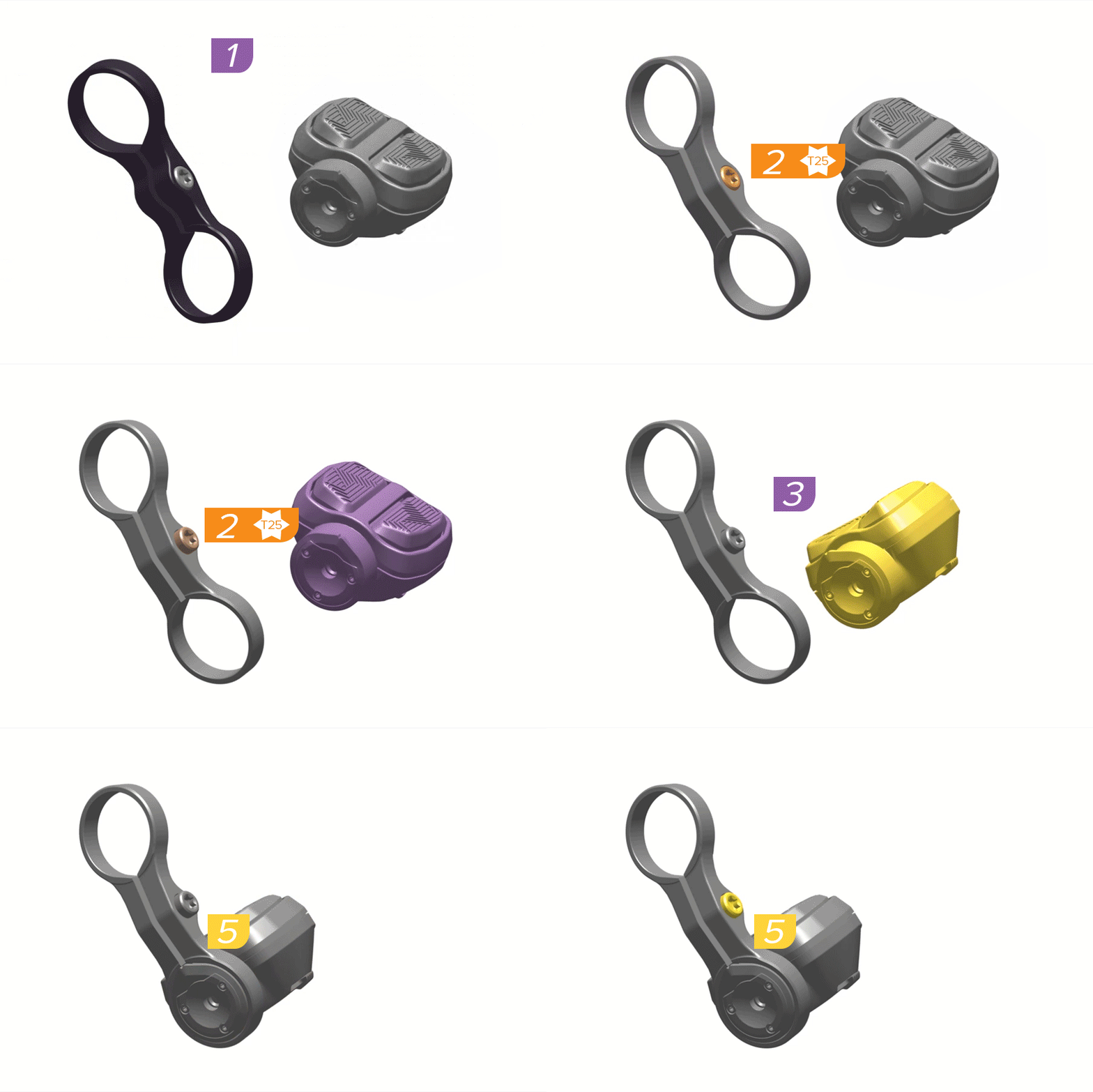
1. Position the clamp in the left handlebar position (1a) or the right handlebar position (1b) before proceeding.
2. Loosen or remove the clamp bolt.
3. Align the pointed tip with the open slot in the clamp.
4. Install the Pod Controller into the clamp.
5. Loosely install the clamp bolt.
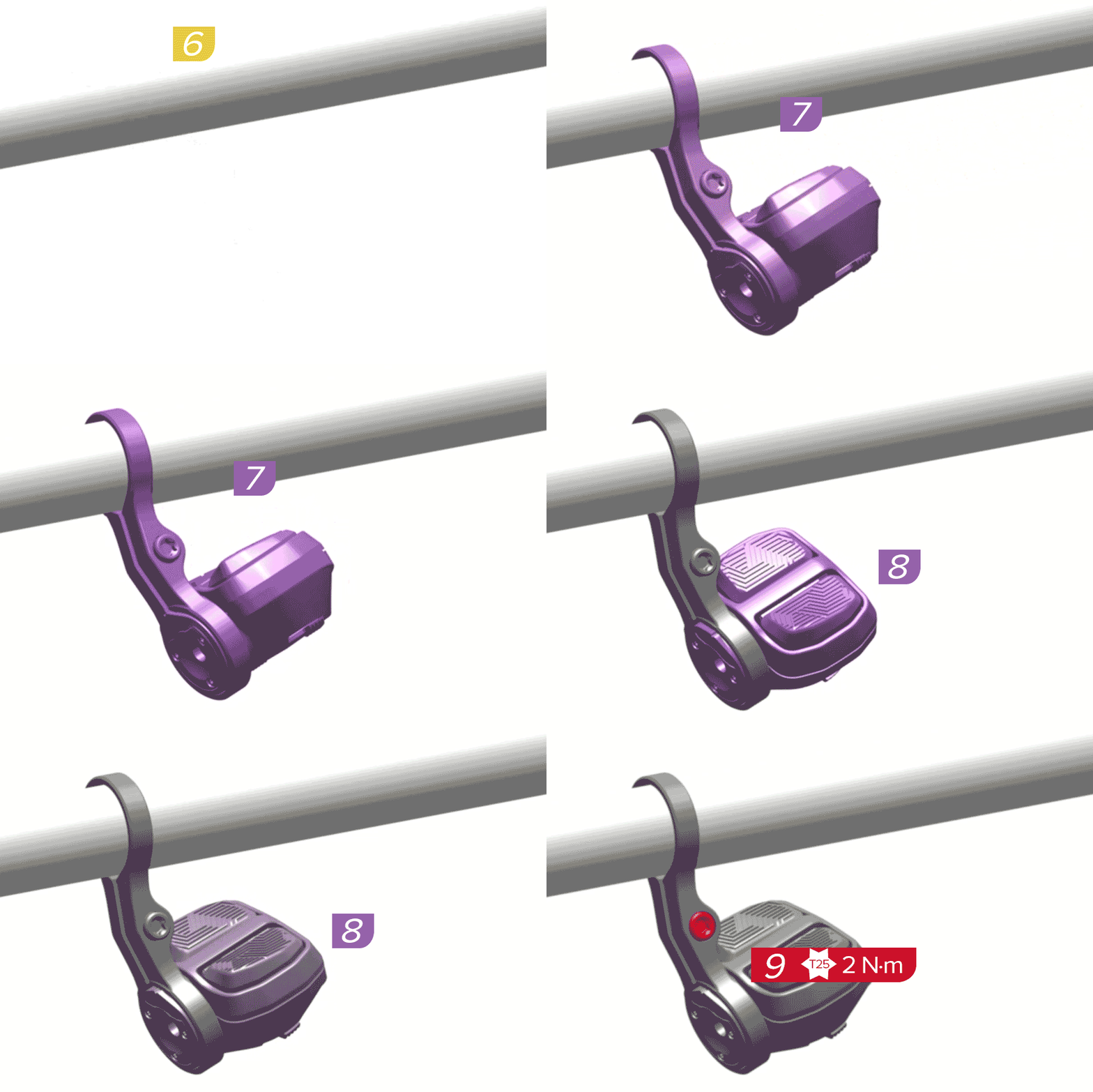
6. Move the clamp horizontally to the desired position on the handlebar.
7-8. Rotate the clamp and controller to the desired angles.
9. Tighten the clamp bolt.
CRASH HAZARD
Make sure the Pod Controller does not obstruct the brake lever throw.
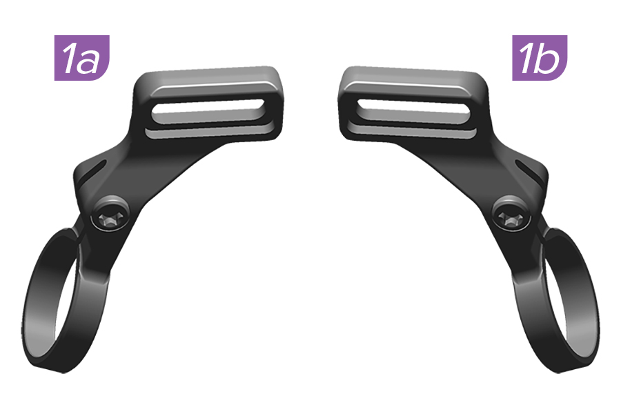
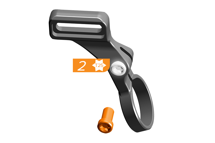
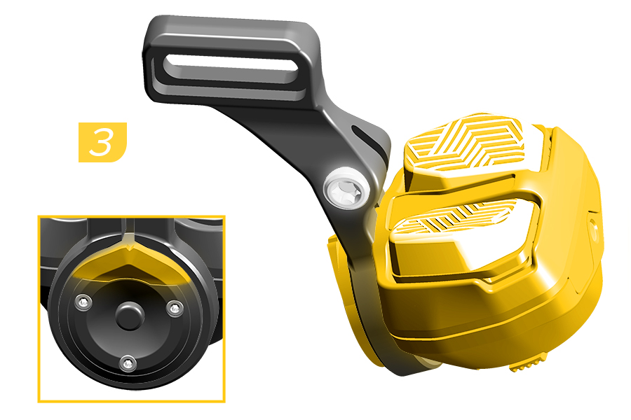
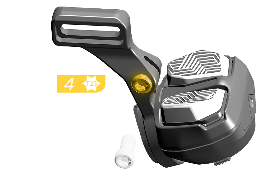
1. Install the left bridge (1a) for the left handlebar position or the right bridge (1b) for the right handlebar position.
2. Loosen or remove the clamp bolt.
3. Install the Pod Controller with the pointed tip aligned with the open slot in the clamp.
4. Loosely install the clamp bolt.
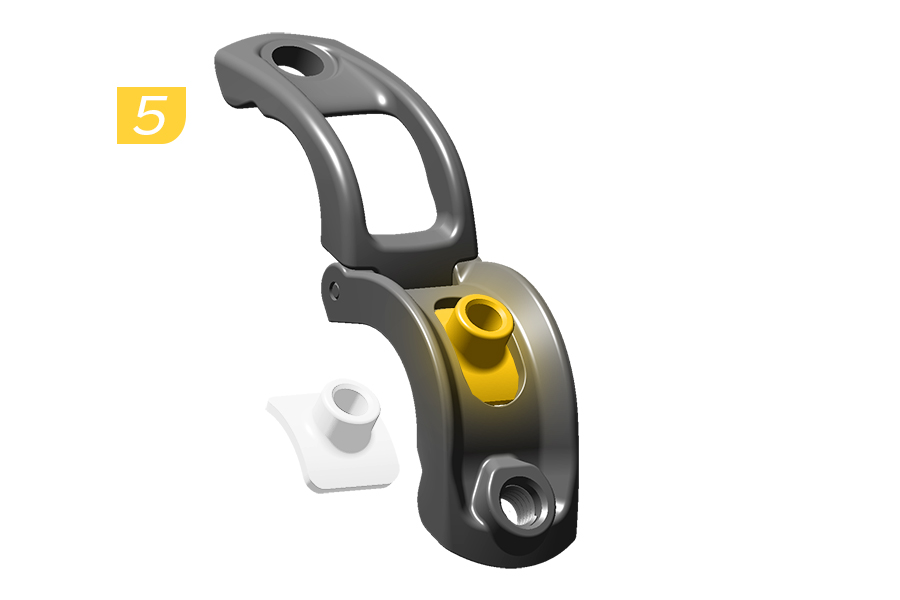
5. Install the T-nut into the clamp.
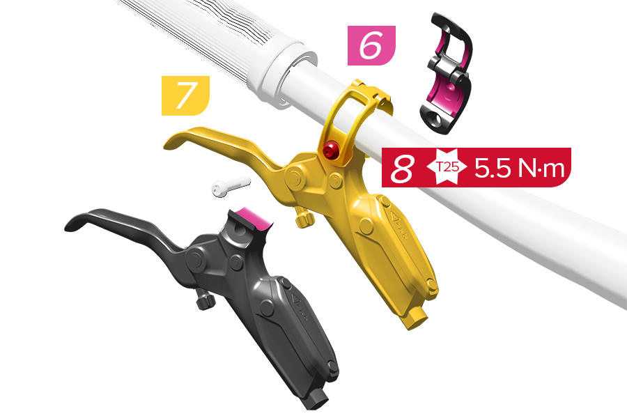
6. Apply friction paste to the clamp surfaces.
7. Loosely install the clamp and brake lever on the handlebar.
8. Tighten the bolt.
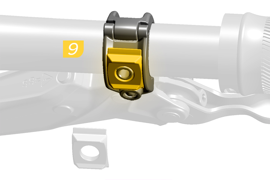
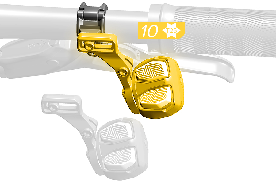
9. Install the slotted washer onto the clamp.
10. Install the bridge.
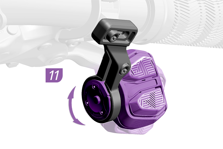
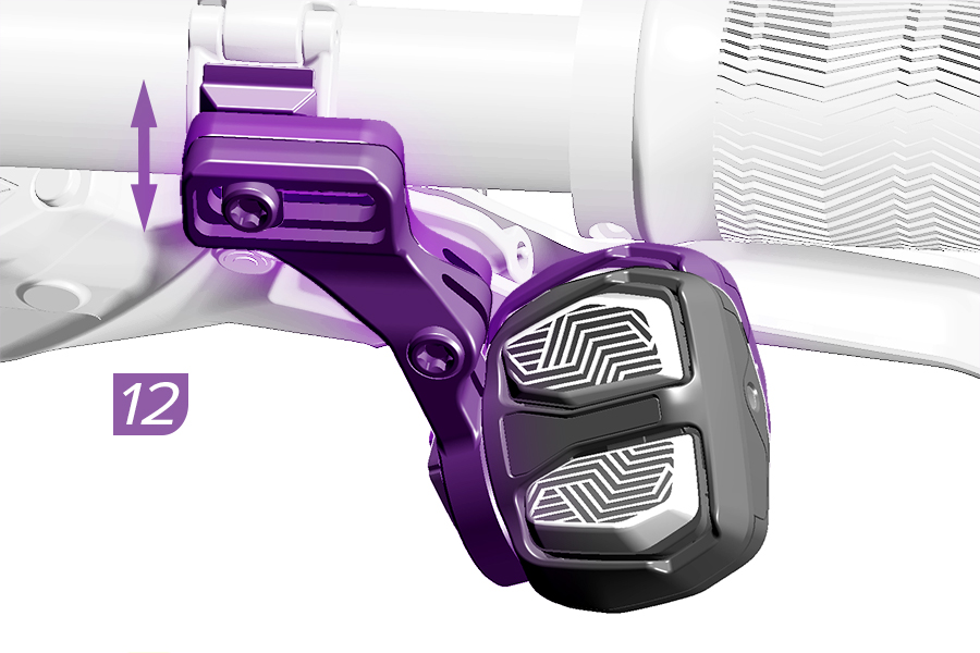
11. Rotate the controller to the desired angle.
12. Move the bridge vertically to the desired position.
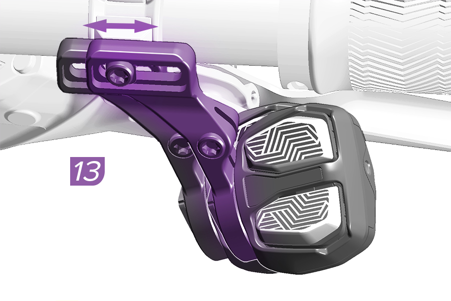
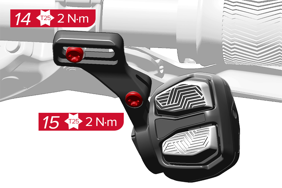
13. Move the bridge horizontally to the desired position.
14. Tighten the bridge bolt.
15. Tighten the clamp bolt.
CRASH HAZARD
Make sure the Pod Controller does not obstruct the brake lever throw.
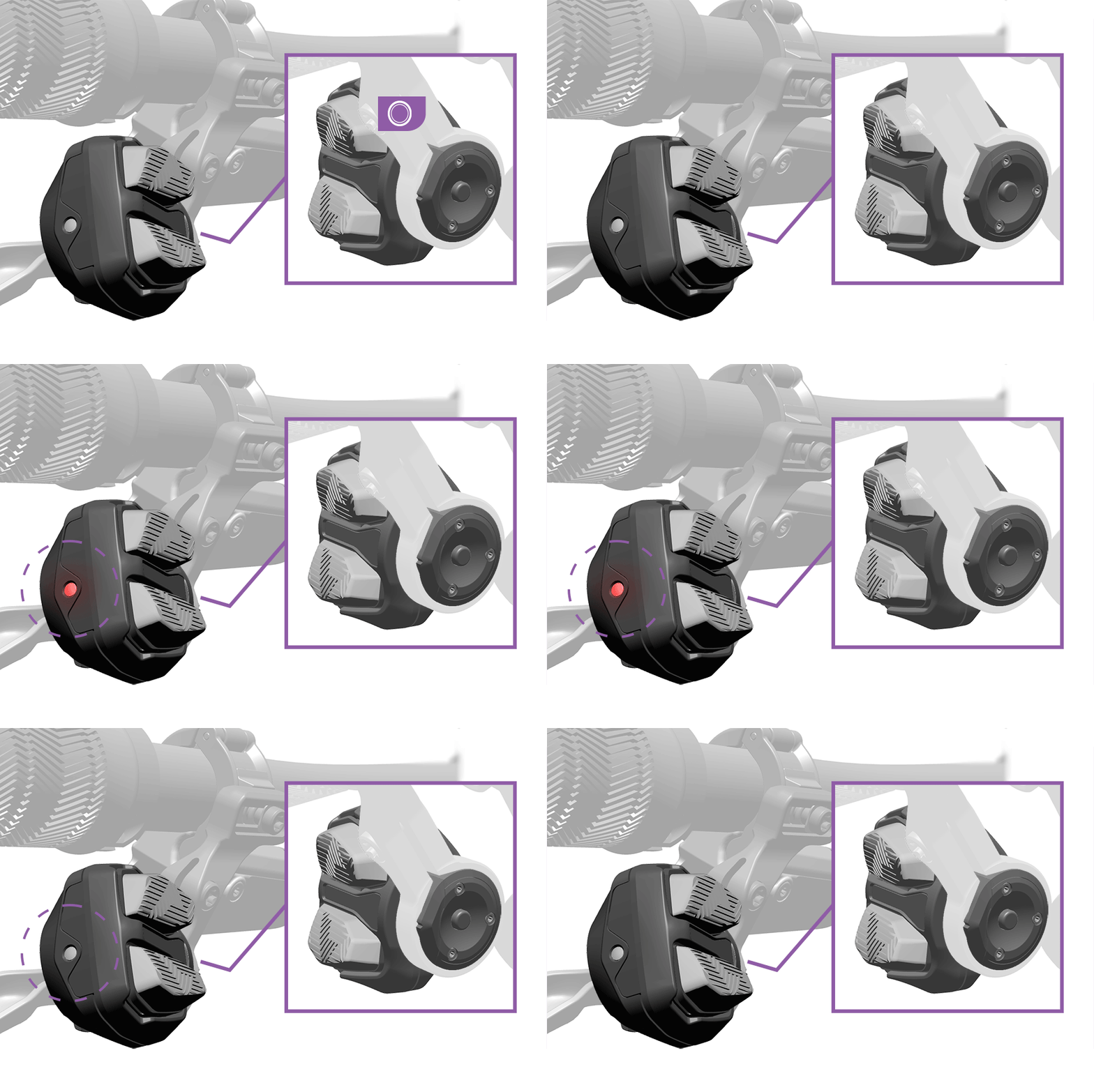
The derailleur begins and ends the pairing session.
The AXS Controller(s) must be paired with the derailleur before use.
Additional AXS components can be paired with the derailleur to create one AXS system. After multiple AXS components have been paired into one system, functions and preferences can be configured in the SRAM AXS app.
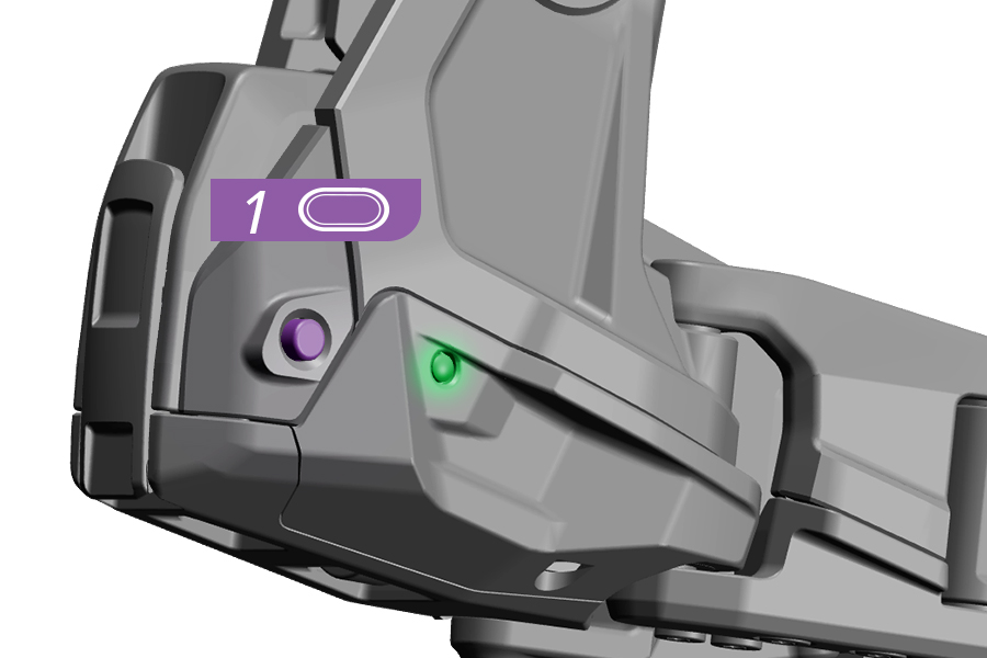
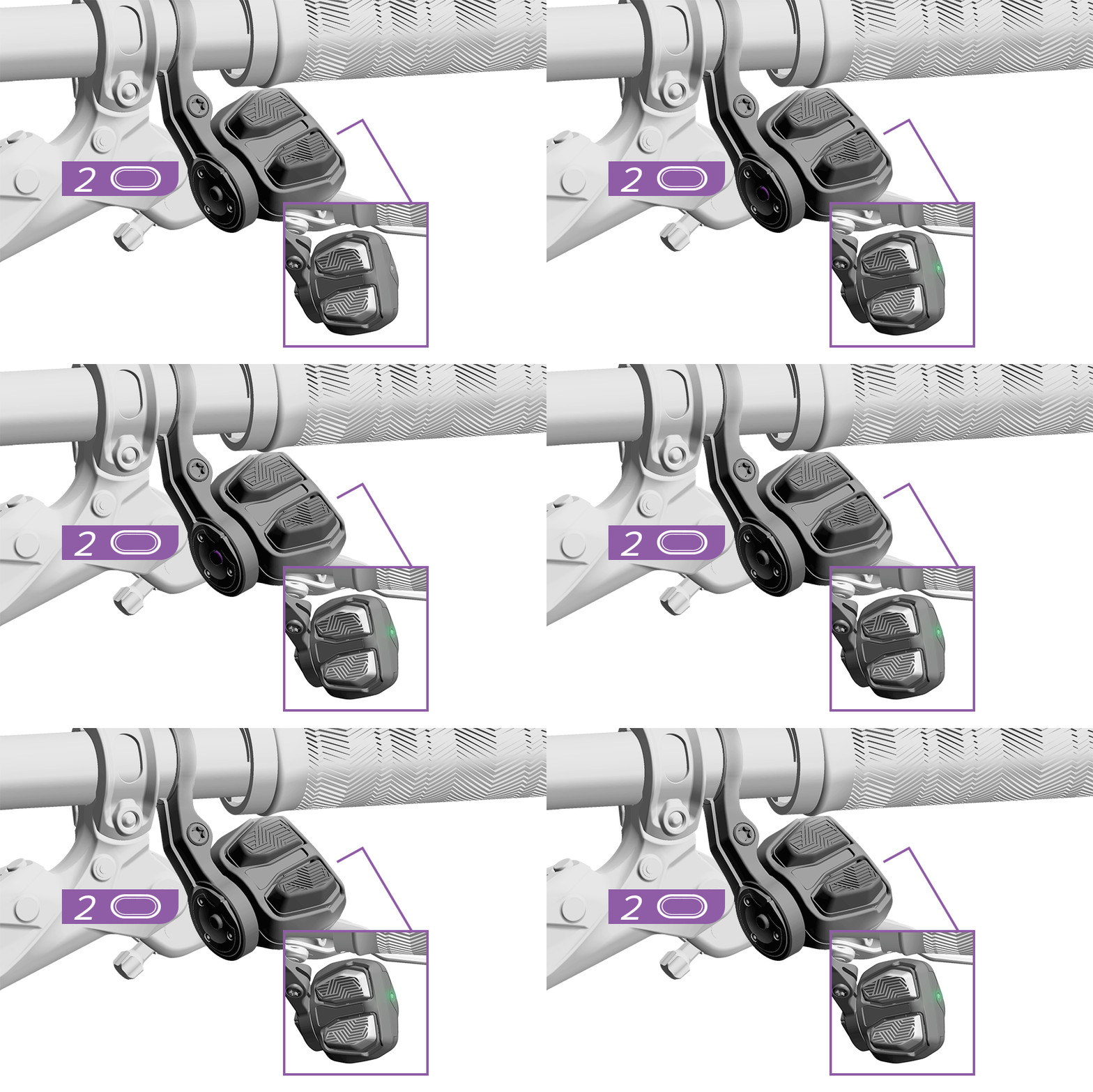
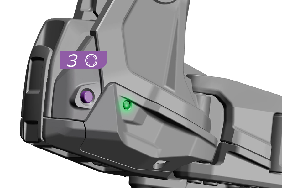
Begin the pairing session with the derailleur.
1. Press and hold the AXS button on the derailleur until the AXS LED blinks slowly, then release.
For setups using two AXS controllers, pair the right controller first.
2. Press and hold the AXS button on the controller until the green LED blinks quickly, then release.
If more than one controller (e.g. Reverb AXS or Left Flight Attendant) is paired into the system, the controller paired into the system first will function as the default right-side controller and is shown as 'Right' in the AXS app.
3. Press and release the AXS button on the derailleur to end the pairing session, or wait 30 seconds for the session to time out. The AXS LED will stop blinking.
Successful pairing can be verified with the SRAM AXS app. All paired components will be listed below the Transmission derailleur.
If any component does not respond, repeat the pairing process. The pairing process does not need to be repeated when any battery is removed and/or replaced. The pairing process must be repeated if any components are replaced, added, or removed.
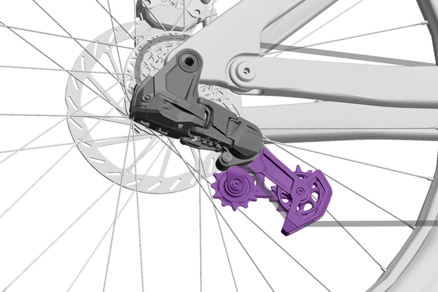
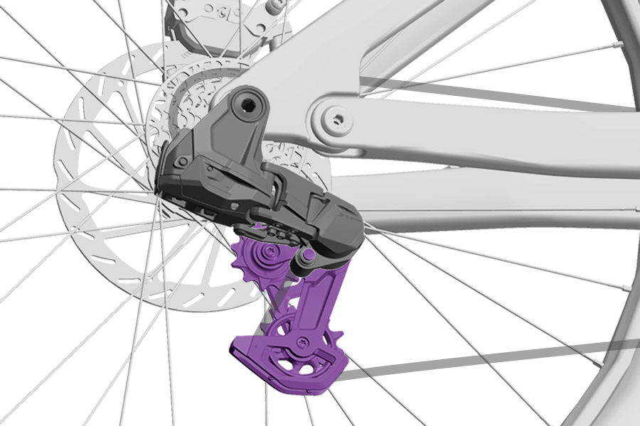
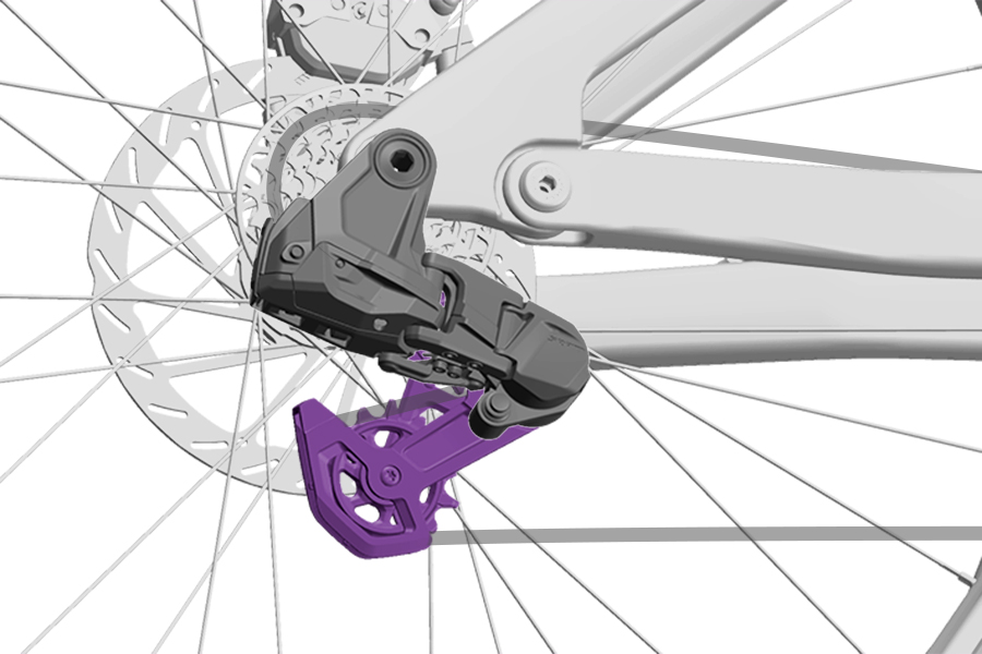
CAGE MODES
The Cage Mode button is used to position the derailleur cage to the various Cage Modes.
Open Mode: The derailleur cage is fully extended for rear wheel removal and installation.
Setup Mode: The derailleur cage is slightly extended to align the cage with the key line and to position the derailleur for specific installation procedures.
Ride Mode: The Cage Mode button is not depressed, and the derailleur cage is unlocked and not extended.
This section covers preparing the Chain Length and determining the Setup Cog for installation. Do not install the components onto the frame until the next section, Hang the Components.
Consult the SRAM Full Mount Chain Length Guide or use the SRAM AXS app to determine the chain length calculated for your bicycle.
If your bicycle is not listed in the guide or app or if you have an adjustable idler pulley not in the default position, you must consult the Categorization section and use the chain gauge tool to determine the Chain Length and Setup Cog for your frame setup.
The SRAM Full Mount Chain Length Guide offers the most accurate recommendations and should be used whenever possible and referenced as the default. Recommendations provided by the chain guide may differ from the Chain Length Table.

1. Count down from 126 to the number of chain links determined by the guide or app.
2. Use an approved chain breaker tool to break the chain at the inner link. Set the chain aside.
For a list of approved chain tools, consult the Eagle, Flattop, and 11 Speed Chain Compatible Tools document.
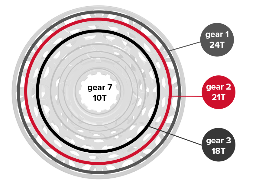
Consult the SRAM Full Mount Chain Length Guide or use the SRAM AXS app to determine the Setup Cog for your bicycle.
If your bicycle is not listed in the guide or app, you must consult the Categorization section and determine the Setup Cog for your frame setup.
3-4. Install and tighten the cage assembly onto the derailleur body, if needed.
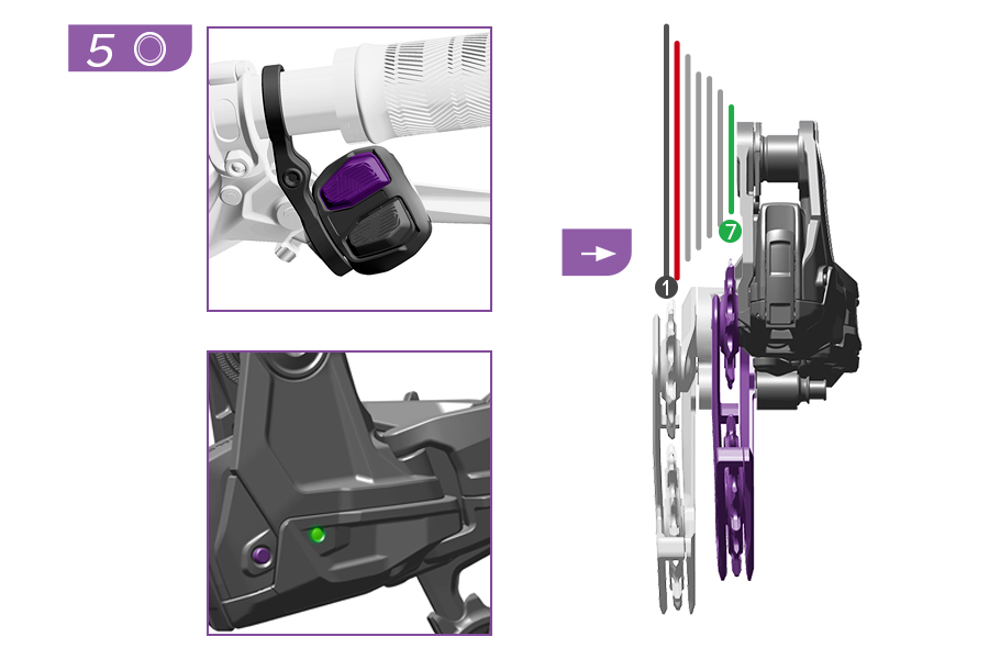
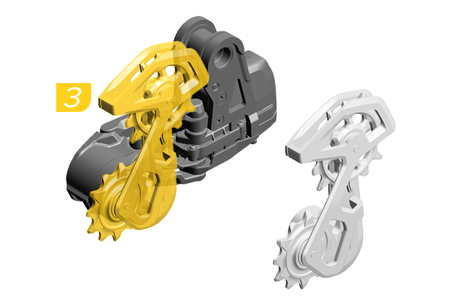
5. Press and release the top button on the controller to shift the derailleur outboard one position at a time until it is fully outboard. Alternatively, press and release the AXS button on the derailleur to move the derailleur outboard one position at a time until it is fully outboard.
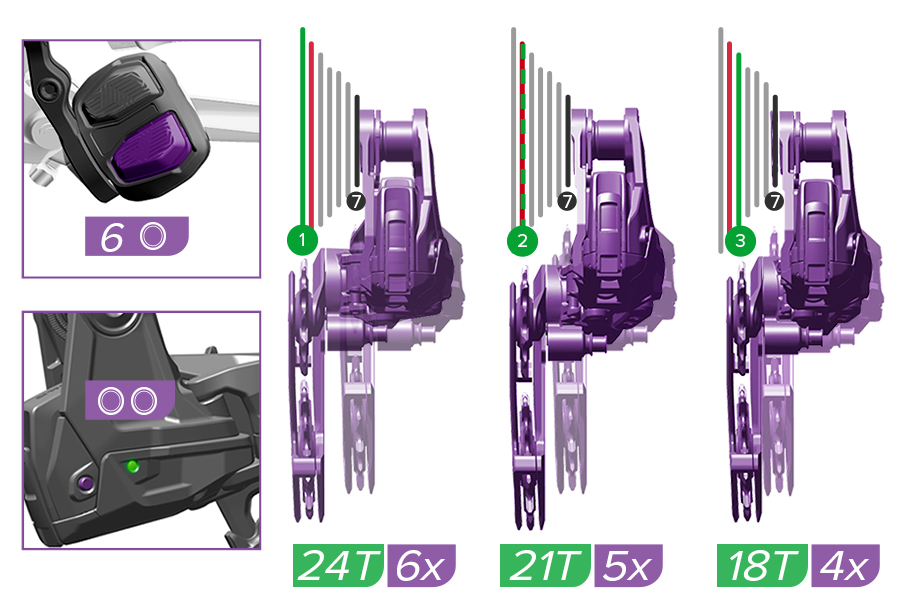
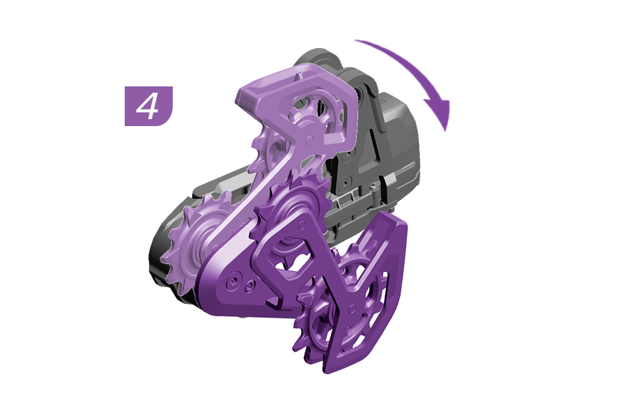
6. Shift the unmounted derailleur into the Setup Cog Position, Gear 1 (24T Cog), Gear 2 (21T Cog), or Gear 3 (18T Cog), as determined in AXS app or in the Categorization section.
Gear 1, 24T Setup Cog: Press the bottom button on the controller six clicks from full outboard position to shift the derailleur into position for Gear 1 (24T Cog).
Gear 2, 21T Setup Cog: Press the bottom button on the controller five clicks from full outboard position to shift the derailleur into position for Gear 2 (21T Cog).
Gear 3, 18T Setup Cog: Press the bottom button on the controller four clicks from full outboard position to shift the derailleur into position for Gear 3 (18T Cog).
Alternatively, press the AXS button on the derailleur twice quickly to move the derailleur inboard until it is in the Setup Cog Position.
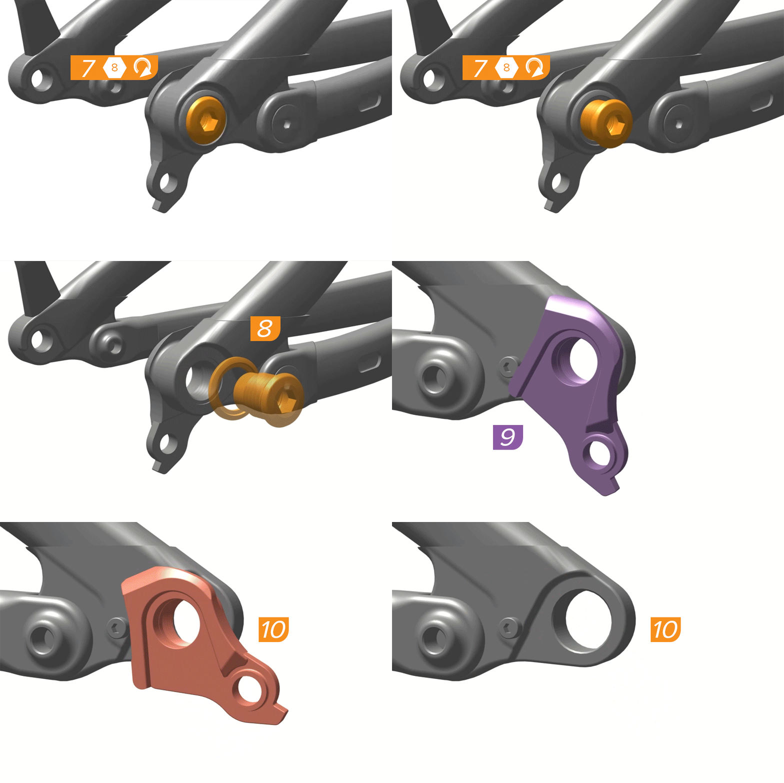
The UDH must be removed from the frame before derailleur installation.
7. Turn the UDH bolt clockwise.
The UDH bolt is left-hand threaded. To loosen the bolt, turn clockwise.
8. Remove the bolt and washer from the hanger threads.
9. Rotate the UDH hanger backward to unseat the hanger from the pocket.
10. Remove the UDH hanger from the frame.
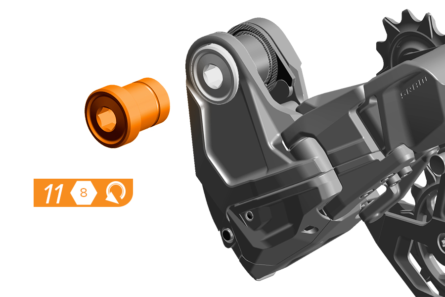
11. Remove the mount bolt.
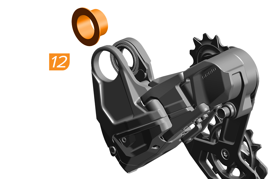
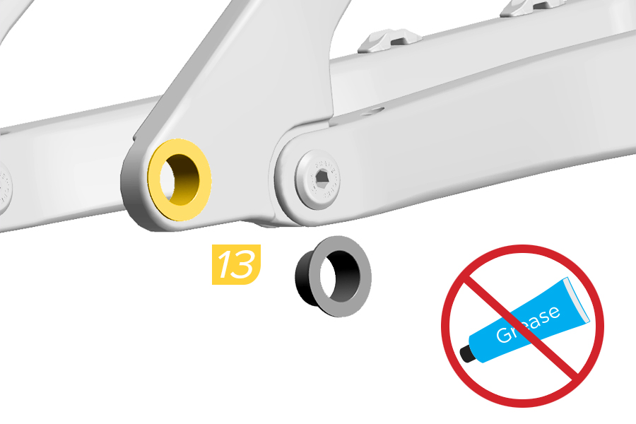
12. Remove the bushing frame insert.
Clean the frame to remove any grease or debris.
13. Install the bushing frame insert from the outside with the black side facing outwards into the hangerless interface of the frame.
Split Pivot Frames: Install the washer between the pivot bearings of bicycles with split pivots.
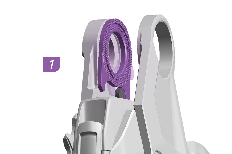
1. Rotate the knurled ring clockwise until it is touching the knurled ring stop. Make sure the ring stop is between the knurled ring horns.
2. Apply grease to the mount bolt threads and underside of the bolt flange.
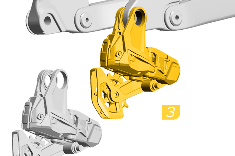
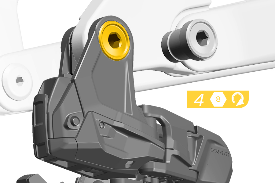
3. Install the Transmission derailleur with the full mount sliding over the hangerless interface and bushing frame insert.
4. Install and tighten the mount bolt clockwise to snug.
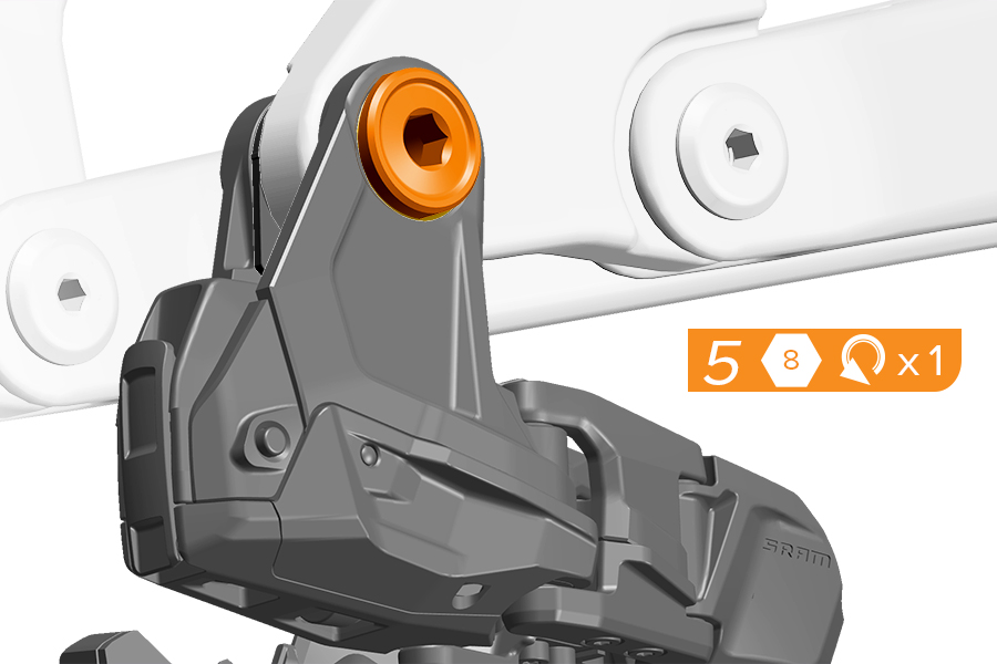
5. Loosen the mount bolt counter-clockwise one full turn.
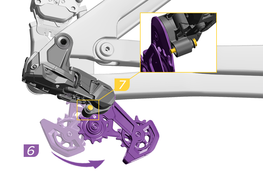
6. Rotate the derailleur cage forward until the lock icon on the cage clears the Cage Mode button.
7. Press the Cage Mode button to position the derailleur cage in Open Mode.
PINCH HAZARD
The derailleur is spring-loaded and will return from the Open Mode position rapidly. Keep fingers clear of pinch points.
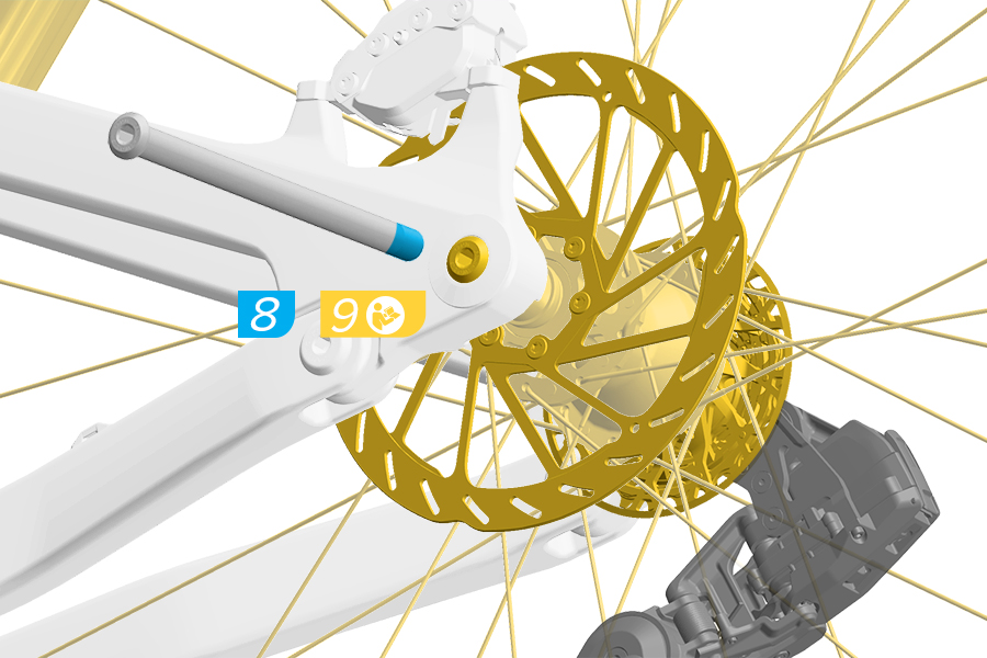
8. Apply grease to the thru axle threads before axle installation.
9. Install the thru axle and wheel according to the manufacturer's instructions.
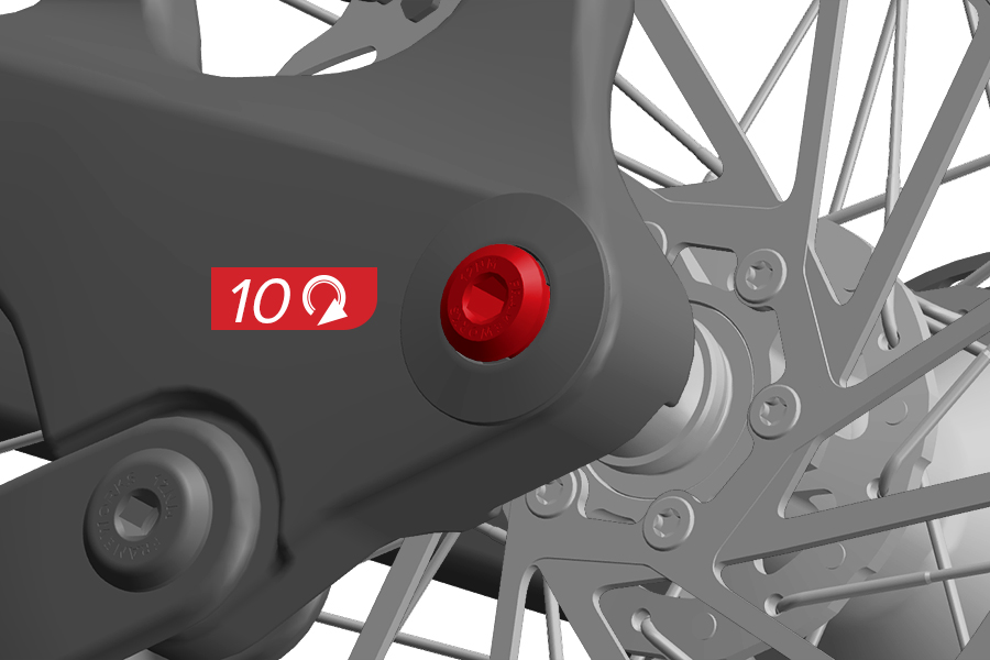
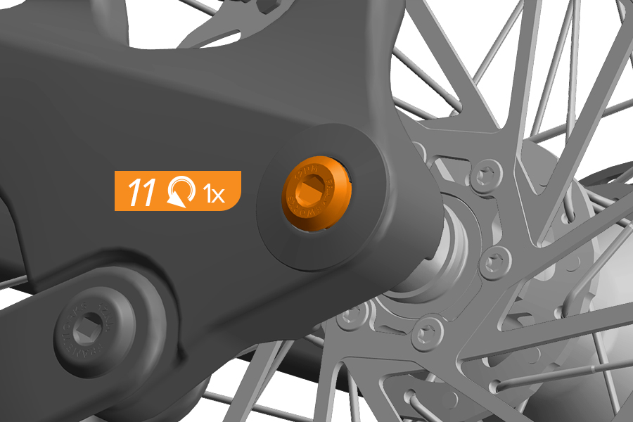
10. Tighten the axle to snug.
11. Loosen the thru axle counter-clockwise one full turn.
Failure to loosen the thru axle one turn will result in improper system installation. The thru axle will be tightened at the end of system installation.
Verify the chain has been cut to the proper size and the DH Transmission derailleur is shifted into the Setup Cog as determined in AXS web or AXS app or the Categorization section.
E-bikes must be powered off before proceeding.
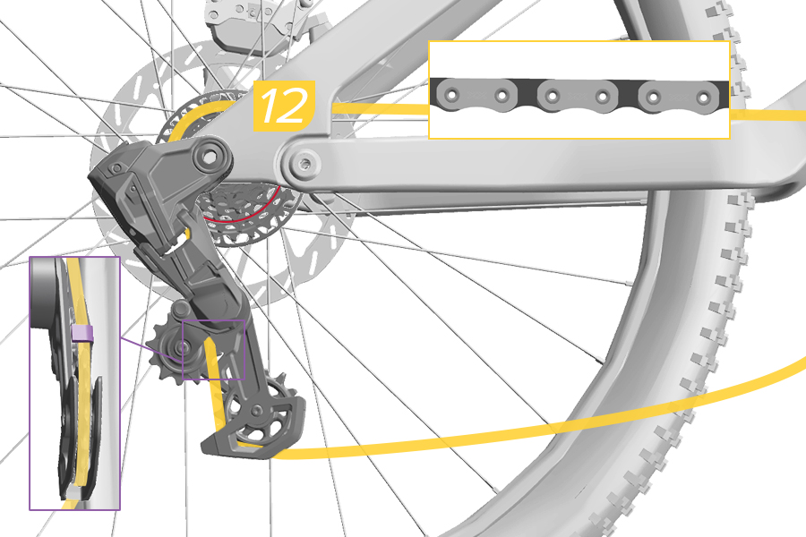
12. Place the properly sized Eagle T-Type chain on the Setup Cog, 24T, 21T, or 18T, and route through the derailleur pulleys with the flat edge of the chain facing away from the cassette.
Make sure to route the chain below the tab in the cage.
Route through the idler pulley(s), if applicable.
The chain must be seated and engaged on the cassette cog teeth for proper setup.
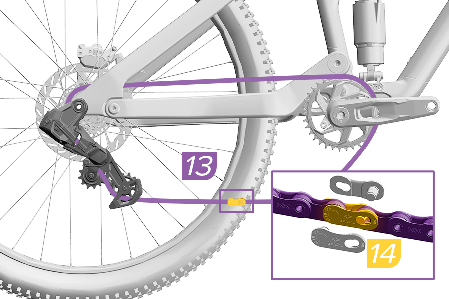
13. Pull each end of the chain together.
14. Install the PowerLock. Press the PowerLock connector links together.
The arrow must point in the direction of chain travel before locking the PowerLock into place. Once locked, the PowerLock must not be used a second time.
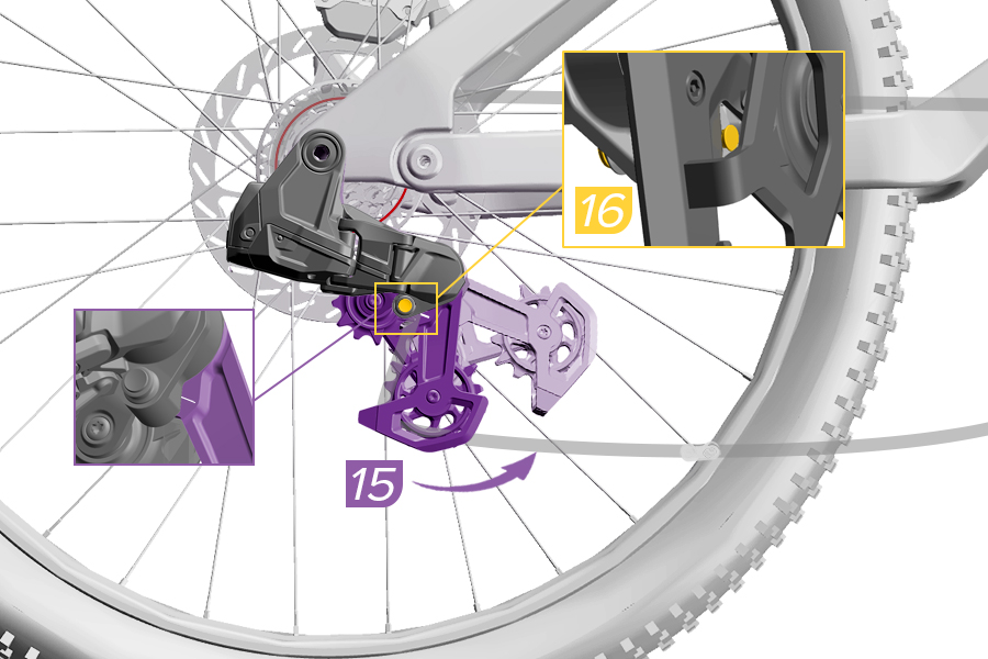
15. Rotate the derailleur cage forward and release the cage from the Open position. Reposition the derailleur cage so that the Cage Mode button aligns with the Key Line mark for Setup Mode position.
16. Press the Cage Mode button to position the derailleur cage in Setup Mode.
PINCH HAZARD
The derailleur is spring-loaded and will return from the Open Mode position rapidly. Keep fingers clear of pinch points.
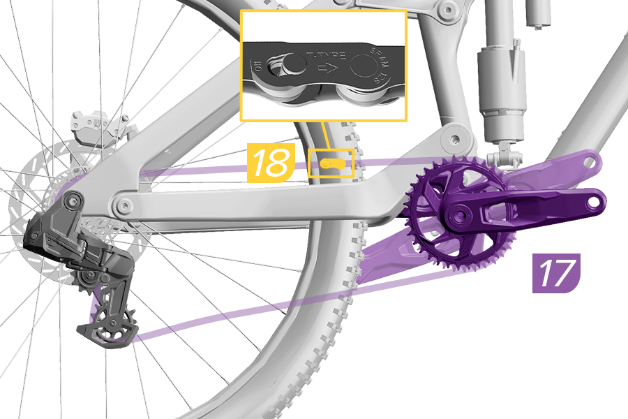
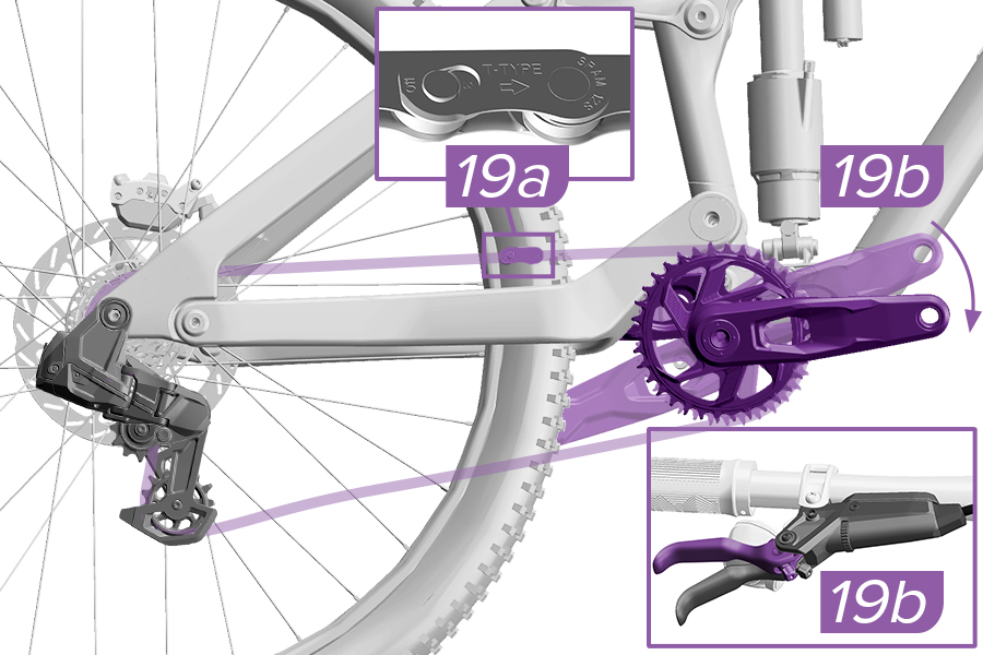
17. Rotate the crank until the PowerLock is above the chainstay.
18. Check that the two halves of the PowerLock are aligned and engaged.
19a. Use chain link pliers to lock the PowerLock.
Alternatively, apply the rear brake (19b) and firmly push the crank arm down (19b) to lock the PowerLock. You should hear and feel the PowerLock click into place.
Check the PowerLock by hand to make sure it moves freely.
The PowerLock is designed for one-time use only. The PowerLock can only be removed with chain link pliers and must not be reused. Install a new PowerLock each time a new chain is installed. Reusing a PowerLock may result in a broken chain that could result in a crash.
Before proceeding you must verify the following were completed in the previous sections:
The rear axle and mount bolt have been loosened one full turn.
The derailleur is in the Setup Mode.
The chain is placed on the Setup Cog for your bicycle and is properly engaged on all cogs in the system.
The PowerLock is closed.
The bicycle suspension is uncompressed, at 0 percent sag, unless otherwise instructed.
The bicycle suspension is uncompressed, at 0 percent sag, unless otherwise instructed.
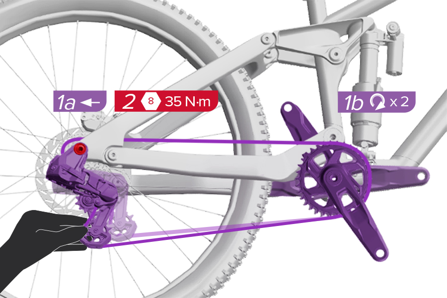
1a. Pull back on the lower cage of the Transmission derailleur to remove slack from the chain.
1b. Continue to pull back while you rotate the crank forward two rotations while confirming the chain stays on the Setup Cog.
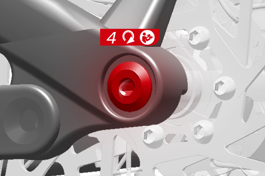
2. Tighten the mount bolt while continuing to pull back (1a) on the lower cage of the derailleur, then release.
For downhill bicycles using Gear 3 (18T Cog) or Gear 1 (24T Cog), you must make sure the chain is fully seated on the X-Sync cassette cog profile with two full crank rotations. Adjust the chain as needed.
If there is still slack in the chain after tightening the mount bolt, loosen the mount bolt, then repeat steps 1 and 2.
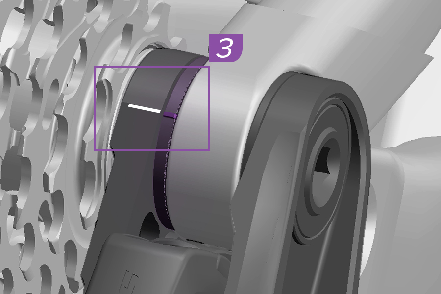
3. Verify the knurled ring mark is aligned with the mark on the full mount of the derailleur.
If it is not aligned, loosen the axle mount bolt one turn, rotate the knurled ring so that it is touching the knurled ring stop, then repeat steps 1-3.
4. Tighten the rear axle to torque according to the frame or axle manufacturer's instructions.
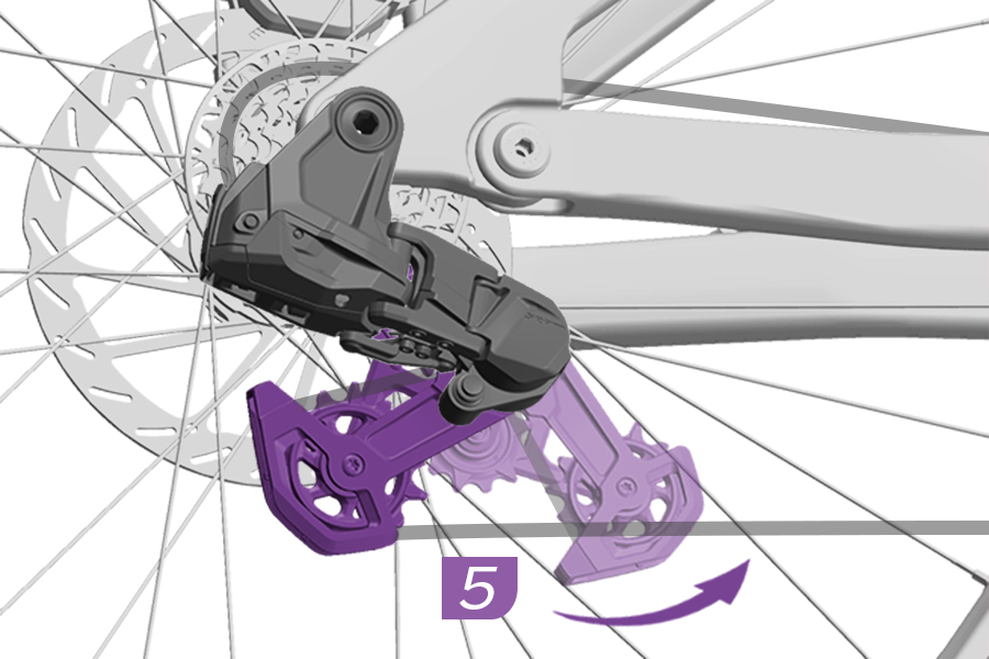
5. Release the cage from Setup Mode to Ride Mode by rotating the cage forward and then carefully letting it return to the unlocked position.
This completes the system installation. There are no adjustment screws in this system. You must repeat the complete installation procedure if you change any of the following on your bicycle: chainring size, geometry adjustment to chainstay length, replace the chain, or reposition or addition of an idler pulley.
Failure to repeat the complete installation process when changing chainring size, idler pulley position, bike geometry, or after replacing the chain, may result in damage to your system or poor drivetrain performance.
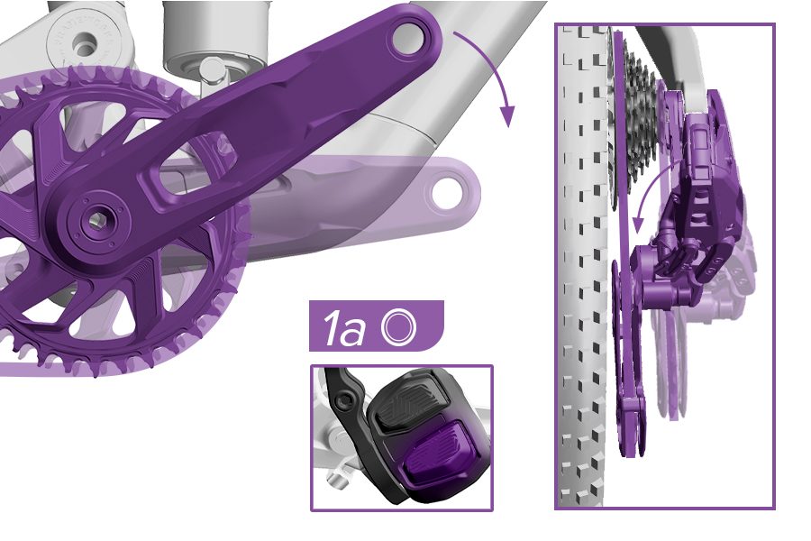
1a. Rotate the cranks slowly and press the bottom button on the AXS Pod Controller to shift the derailleur all the way inboard.
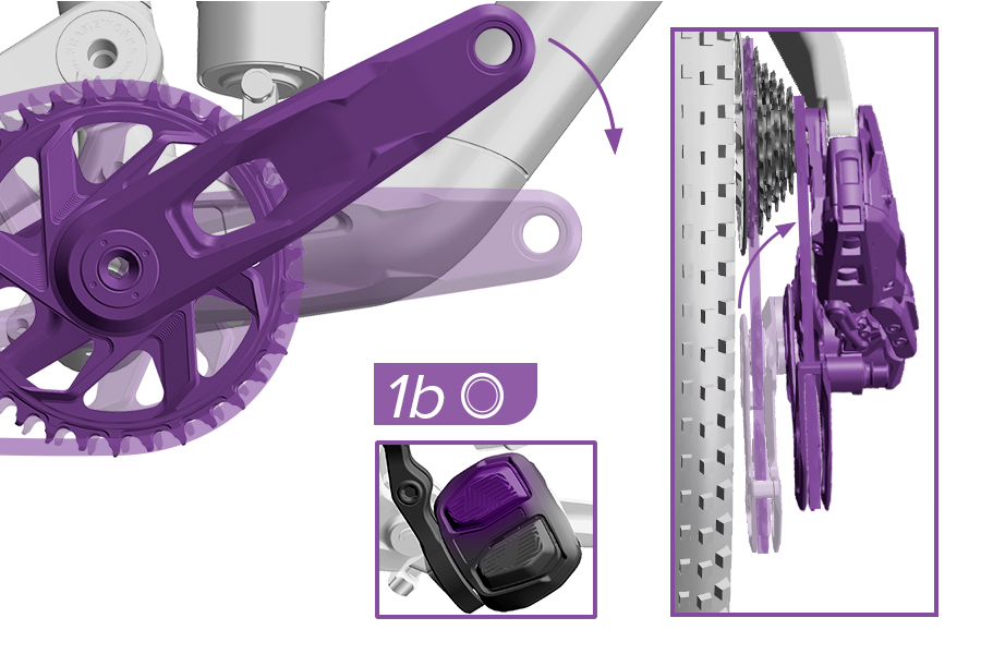
1b. Rotate the cranks slowly and press the top button on the AXS Pod Controller to shift the derailleur all the way outboard.
If the derailleur cage was not released during setup, it will automatically release during the inboard shifting to Ride Mode.
The pulleys may appear to be unaligned; they are intentionally offset to improve chain travel and direction.
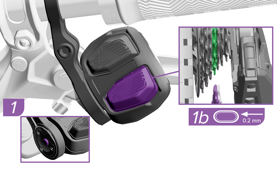
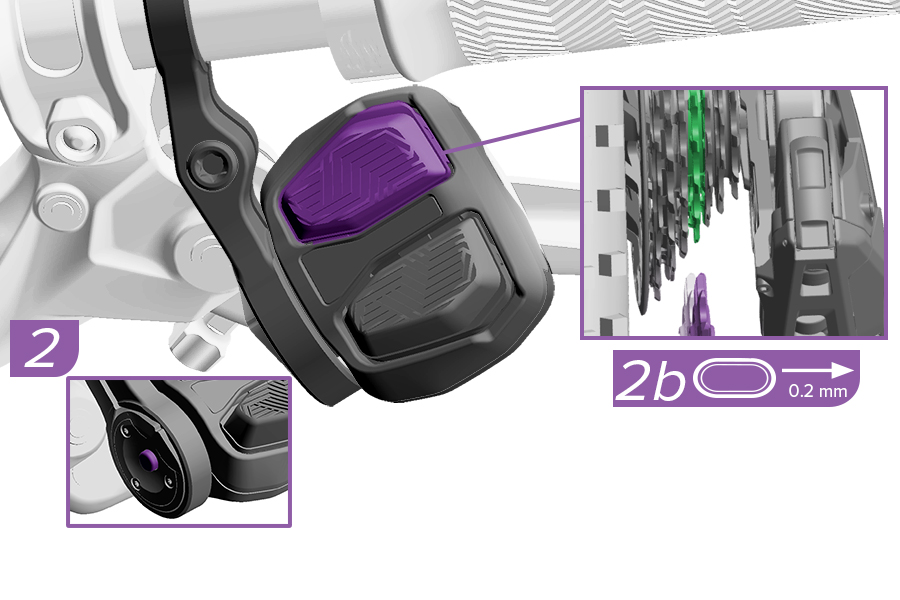
Optimize derailleur shift performance and eliminate unwanted rasping sounds by fine-tuning the derailleur position with MicroAdjust. MicroAdjust affects derailleur position across all of the cogs. There is no independent adjustment for each cog.
1. Press and hold the controller AXS button while pressing the lower controller button (1b). This will adjust the derailleur 0.2 mm inboard and improve shifting to an inboard cog.
2. Press and hold the controller AXS button while pressing the upper controller button (2b) to adjust the derailleur outboard. This will adjust the derailleur 0.2 mm outboard and improve shifting to an outboard cog.
The derailleur may not appear to move. Watch for the LED to blink to confirm the derailleur executed the command.
For the best shifting performance, the fine tuning of the derailleur should be done with the bicycle's rear suspension in the sagged, riding position.
CRASH HAZARD
Make adjustments while stationary and ride to test the adjustments. Stop in a safe place to make further adjustments. Do not make adjustments while riding as this could lead to loss of control or injury.
Use the SRAM AXS app as an alternative method to perform MicroAdjust when the bicycle setup does not include or allow access to the shifter AXS buttons.
This section covers determining the Chain Length and Setup Cog Position on bicycle frames not listed in the SRAM Full Mount Chain Length Guide or AXS App, or frames with an adjustable idler pulley not in the default position.
For frames with an adjustable idler pulley: You must position the idler pulley in the desired position before beginning the Categorization section. Consult your idler pulley or frame manufacturer’s instructions for installation.
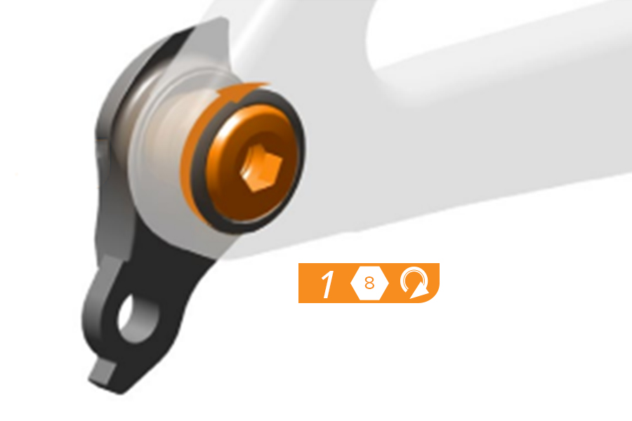
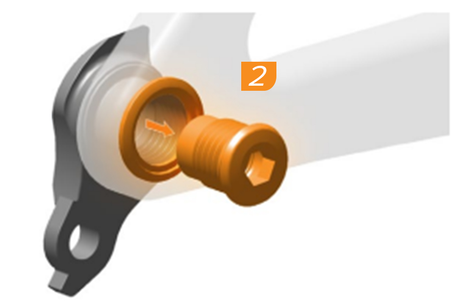
The UDH must be removed from the frame before derailleur installation.
1. Turn the UDH bolt clockwise.
The UDH bolt is left-hand threaded. To loosen the bolt, turn clockwise.
2. Remove the bolt and washer from the hanger threads.
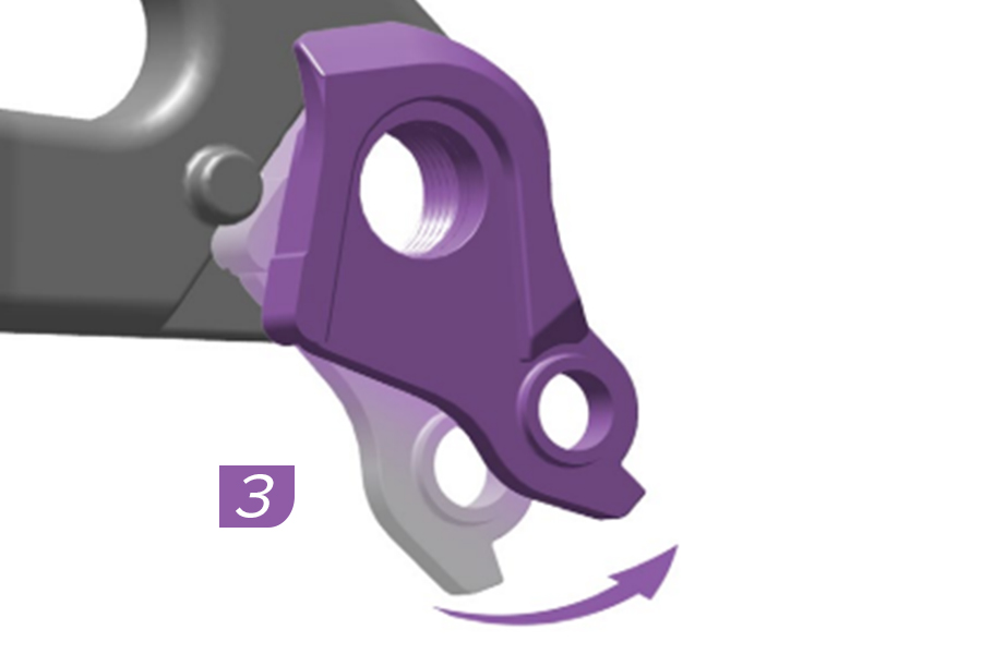
3. Rotate the UDH hanger backward to unseat the hanger from the pocket.
4. Remove the UDH hanger from the frame.
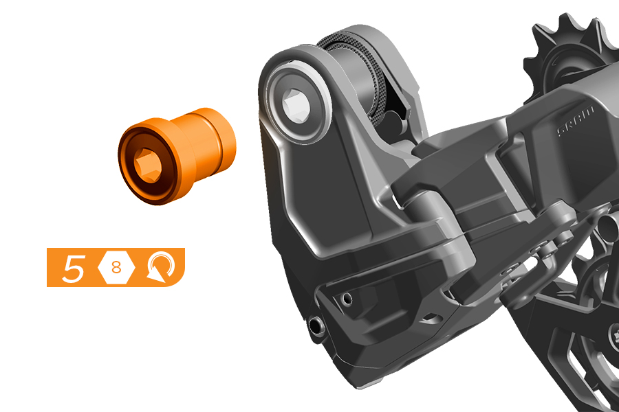
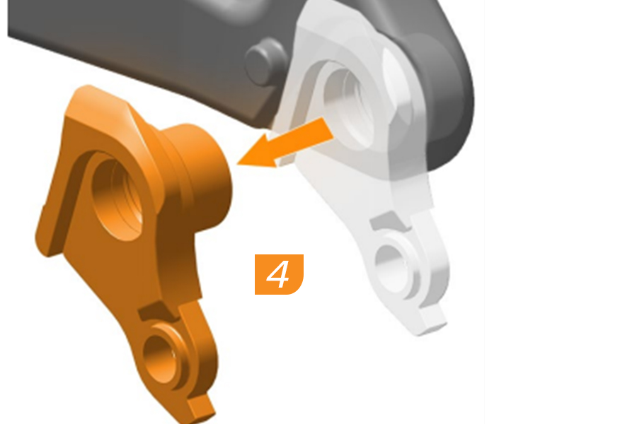
5. Remove the mount bolt.
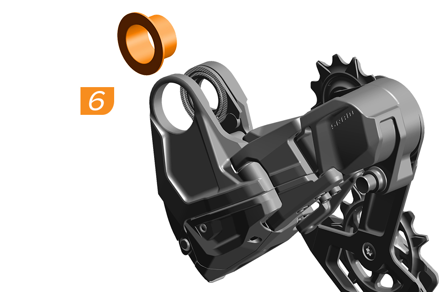
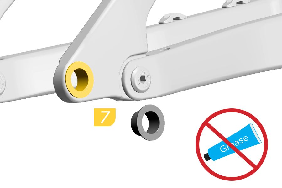
6. Remove the bushing frame insert.
7. Clean the frame to remove any grease or debris. Install the bushing frame insert from the outside with the black side facing outwards into the hangerless interface of the frame.
Split Pivot Frames: Install the washer between the pivot bearings of bicycles with split pivots.
1. Rotate the knurled ring clockwise until it is touching the knurled ring stop. Make sure the ring stop is between the knurled ring horns.
2. Apply grease to the mount bolt threads and underside of the bolt flange.
3. Install the Transmission derailleur with the full mount sliding over the hangerless interface and bushing frame insert.
4. Install and tighten the mount bolt clockwise to snug.
5. Loosen the mount bolt counter-clockwise one full turn.
6. Rotate the derailleur cage forward until the lock icon on the cage clears the Cage Mode button.
7. Press the Cage Mode button to position the derailleur cage in Open Mode.
PINCH HAZARD
The derailleur is spring-loaded and will return from the Open Mode position rapidly. Keep fingers clear of pinch points.
8. Apply grease to the thru axle threads before axle installation.
9. Install the thru axle and wheel according to the manufacturer's instructions.
10. Tighten the axle to snug.
11. Loosen the thru axle counter-clockwise one full turn.
Failure to loosen the thru axle one turn will result in improper system installation. The thru axle will be tightened at the end of system installation.
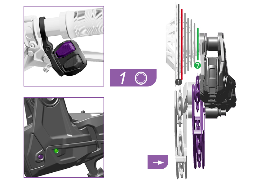
1. Press and release the top button on the controller to shift the derailleur outboard one position at a time until it is fully outboard, Gear 7 (10T Cog). Alternatively, press and release the AXS button on the derailleur to move the derailleur outboard one position at a time until it is fully outboard.
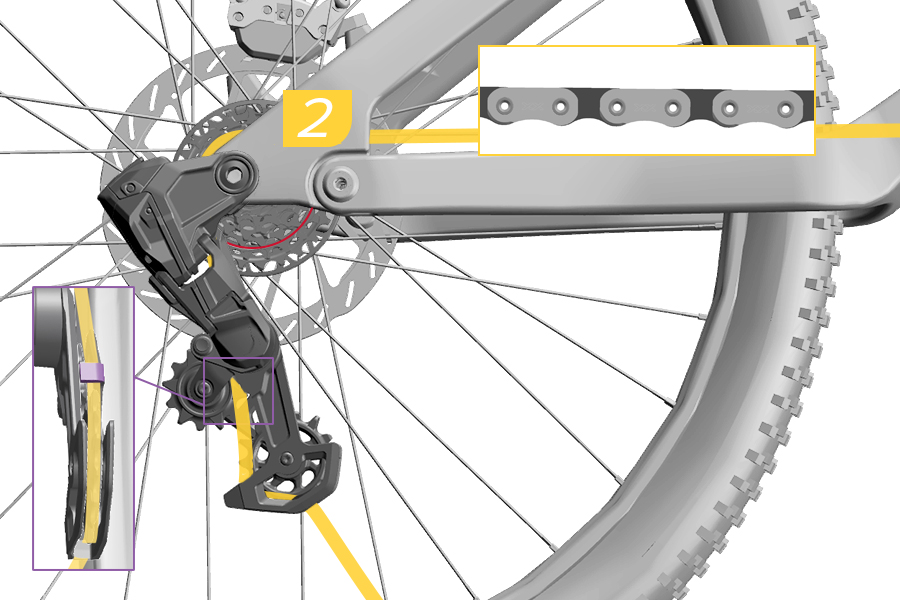
2. Place the unsized Eagle T-Type chain on Gear 7 (10T Cog), and route through the derailleur pulleys with the flat edge of the chain facing away from the cassette.
Make sure to route the chain below the tab in the cage.
Route through the idler pulley(s), if applicable. The chain will remain hanging from the derailleur and chainring until the next section.
The chain must be seated and engaged on the cassette cog teeth for proper setup.
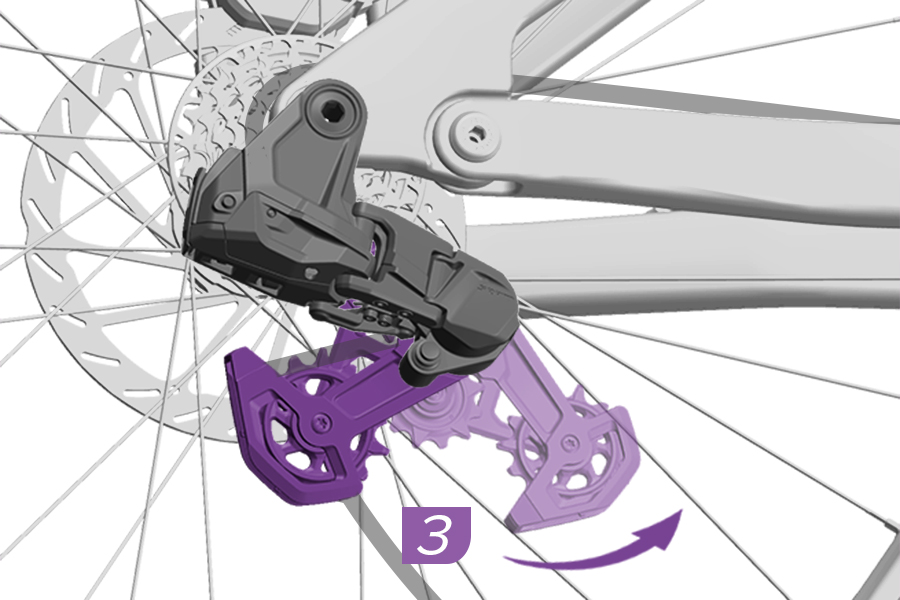
3. Rotate the derailleur cage forward and release the derailleur cage into the unlocked, Ride Mode position.
PINCH HAZARD
The derailleur is spring-loaded and will return from the Open Mode position rapidly. Keep fingers clear of pinch points.

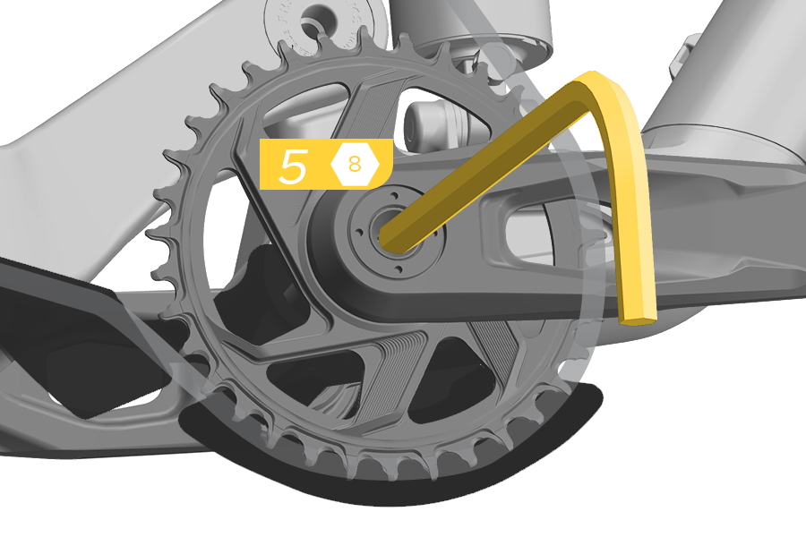
4. Install an 8 mm hex wrench into the mount bolt.
5. Install an 8 mm hex wrench into the crank bolt.

6. Stretch a long rubber band around the hex wrenches. Alternatively, place a long ruler so that it rests on the both hex wrenches.
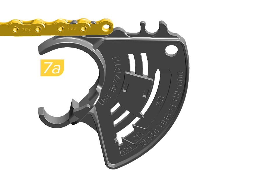
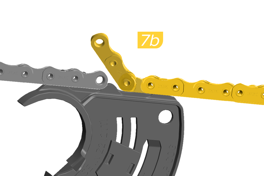
7a. Clip the gauge to an inner link at the end of the chain nearest the derailleur.
7b. Join the two sections of the chain at the gauge. Locate an inner link on the chain closest to the crank that results in the shortest possible chain length without causing the derailleur cage to rotate forward. Clip the inner link onto the gauge.

8a. Pull back on the lower cage of the derailleur to remove slack from the chain.
8b. Tighten the bolt to hold the derailleur in place.


9. Visually inspect the white indicators on the B-knuckle of the derailleur when viewed from the side. The ruler or top of the band should line up within the white indicator lines, as close to the thickest line as possible.
If the ruler or band does not line up within the white indicator lines, then the chain length is not optimal and you must test another chain length. Unclip the gauge, loosen the mount bolt enough to hold the derailleur in place and repeat Steps 7-9. Clip the gauge into a different section of chain.


10. If the ruler or band does line up within the thickest line of the indicators, the chain length is correct. Use an approved chain breaker tool to break the chain at the inner link.
11. Remove the gauge, hex wrenches, and rubber band or ruler.
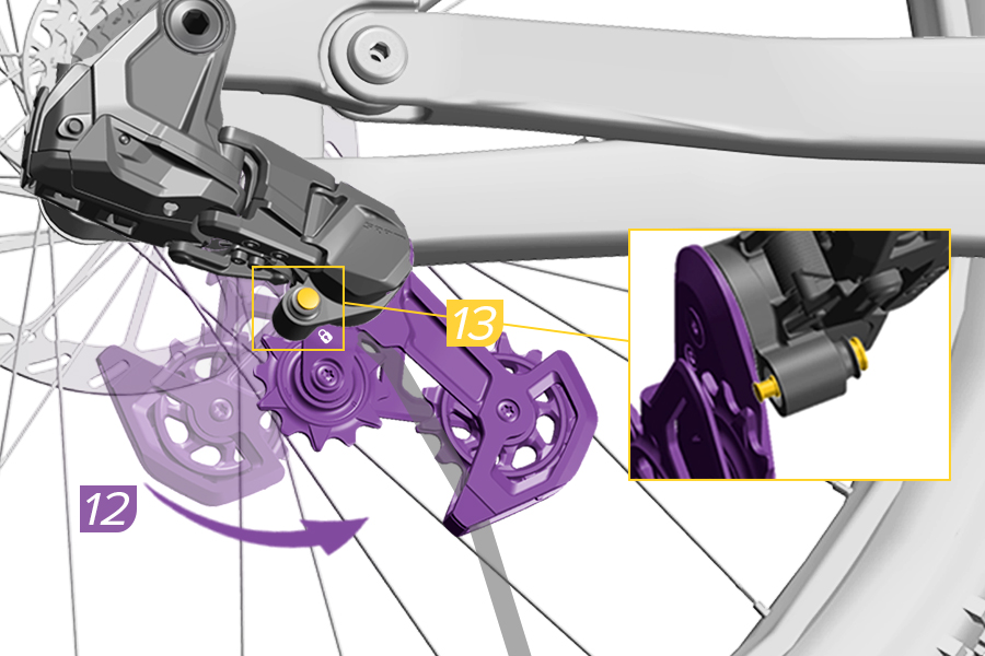
12. Rotate the derailleur cage forward until the lock icon on the cage clears the Cage Mode button.
13. Press the Cage Mode button to position the derailleur cage in Open Mode.
PINCH HAZARD
The derailleur is spring-loaded and will return from the Open Mode position rapidly. Keep fingers clear of pinch points.
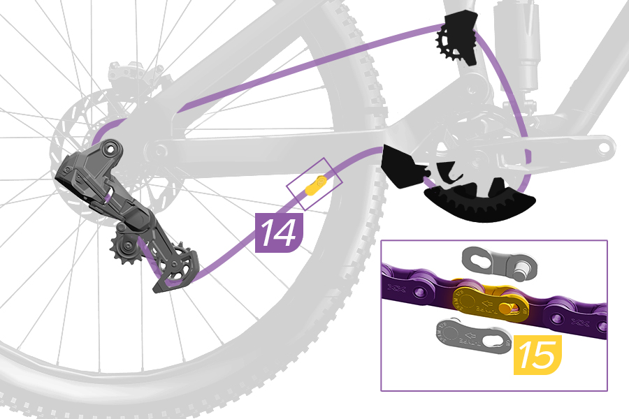
14. Pull each end of the chain together.
15. Install the PowerLock. Press the PowerLock connector links together.
The arrow must point in the direction of chain travel before locking the PowerLock into place. Once locked, the PowerLock must not be used a second time.
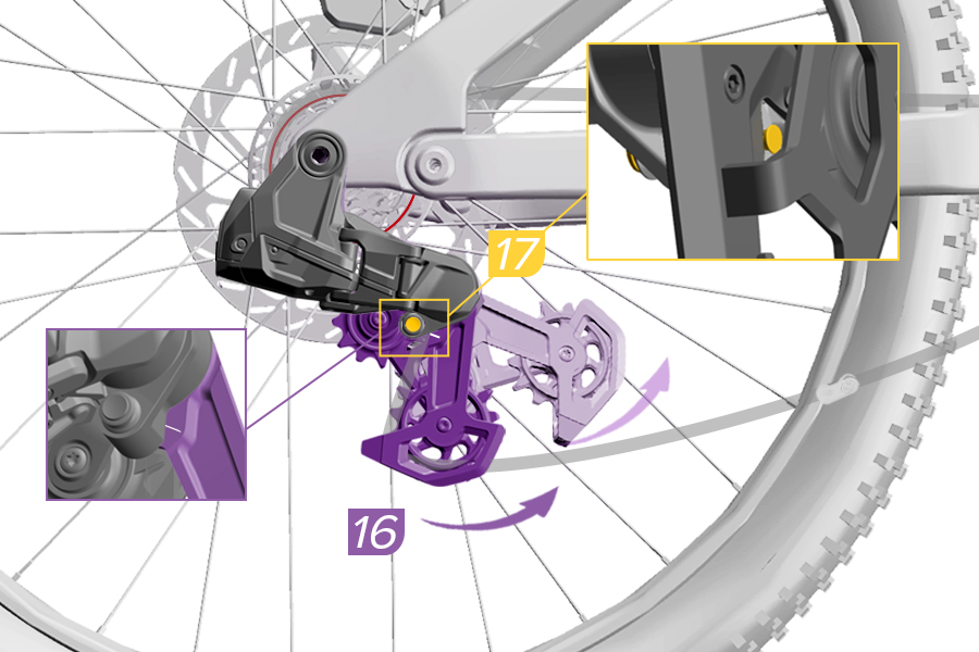
16. Rotate the derailleur cage forward and release the cage from the Open position. Reposition the derailleur cage so that the Cage Mode button aligns with the Key Line mark for Setup Mode position.
17. Press the Cage Mode button to position the derailleur cage in Setup Mode.
PINCH HAZARD
The derailleur is spring-loaded and will return from the Open Mode position rapidly. Keep fingers clear of pinch points.
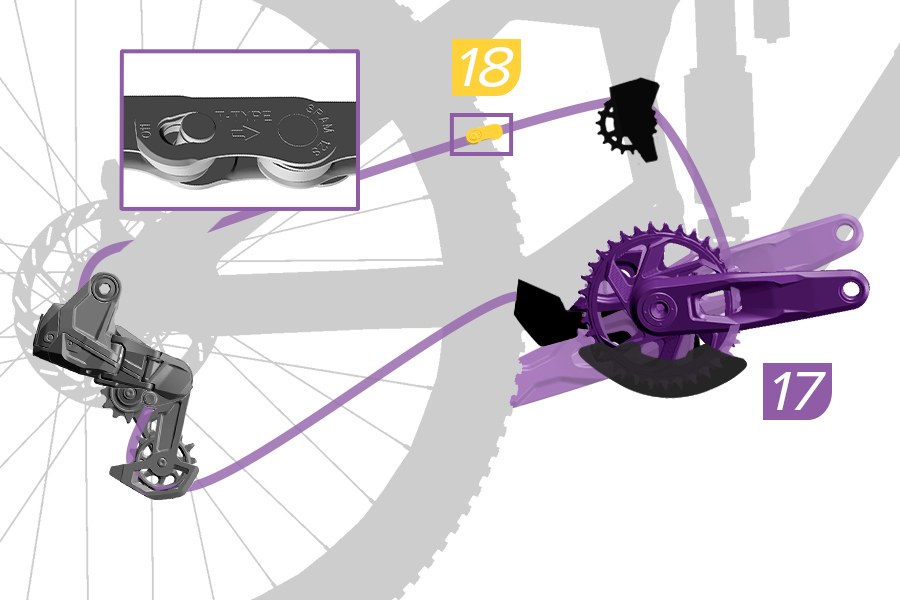
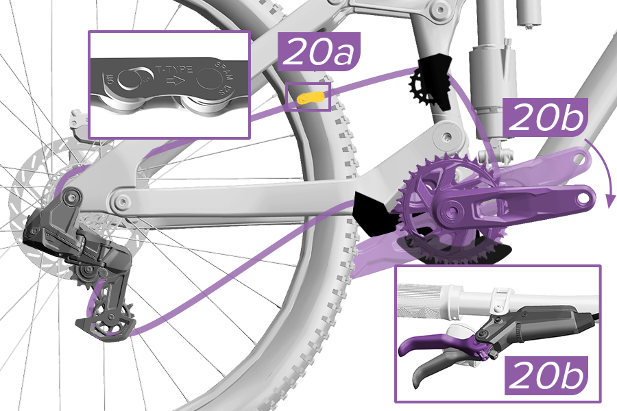
18. Rotate the crank until the PowerLock is above the chainstay.
19. Check that the two halves of the PowerLock are aligned and engaged.
20a. Use chain link pliers to lock the PowerLock.
Alternatively, apply the rear brake (20b) and firmly push the crank arm down (20b) to lock the PowerLock. You should hear and feel the PowerLock click into place.
Check the PowerLock by hand to make sure it moves freely.
The PowerLock is designed for one-time use only. The PowerLock can only be removed with chain link pliers and must not be reused. Install a new PowerLock each time a new chain is installed. Reusing a PowerLock may result in a broken chain that could result in a crash.
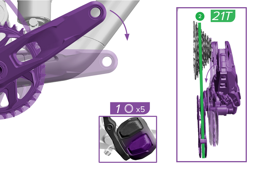
1. With the cage in Setup Mode, shift the derailleur inboard into Gear 2 (21T Cog).
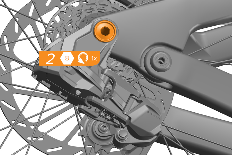
2. Loosen the mount bolt counter-clockwise one full turn.
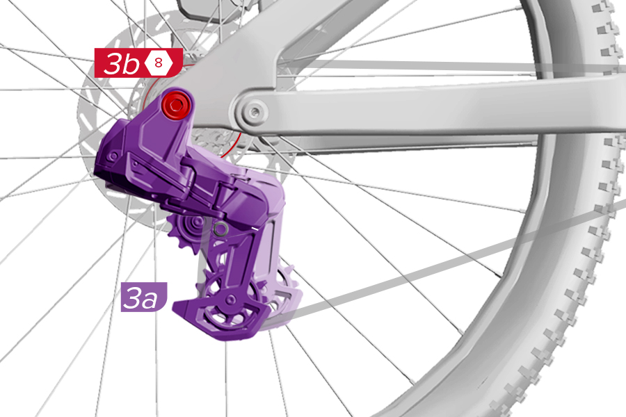
3a. With the derailleur in Setup Mode, pull back on the lower cage of the derailleur to remove slack from the chain.
3b. Tighten the bolt to hold the derailleur in place.
4. Remove the bicycle from the bicycle repair stand.
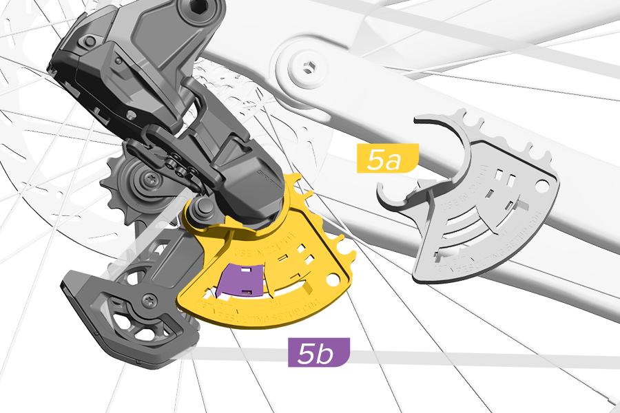
5a. With the derailleur in Setup Mode, hook the gauge around the Setup Key and pull forward around the P-knuckle.
5b. Move the slider on the gauge to the back until the slider touches the cage with a hard stop. This will activate the gauge to identify the Setup Cog.
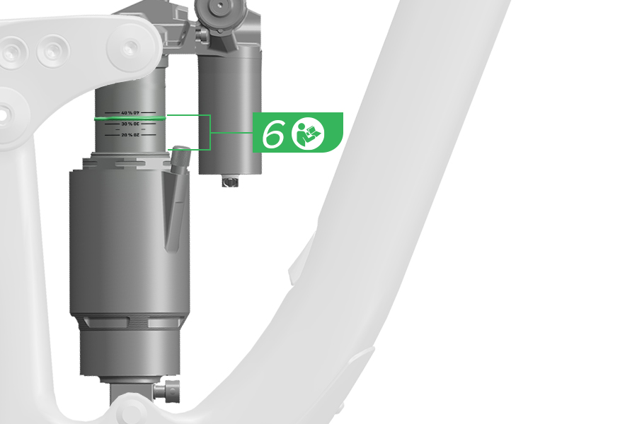
6. Compress or sit on the bike until it is in SAG position.
Suspension sag is the percentage of full travel that the suspension compresses when the rider, including gear, is on the bicycle in a normal riding position.
Consult your frame manufacturer’s recommendations for appropriate sag percentage (typically 20-35%), and your suspension manufacturer's user manual for instructions on setting proper sag.
7. Dismount or un-compress the bike.
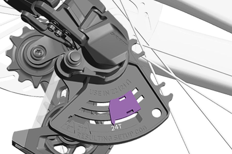
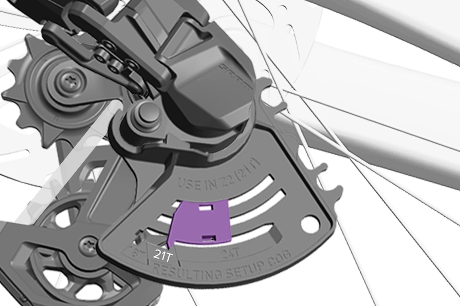
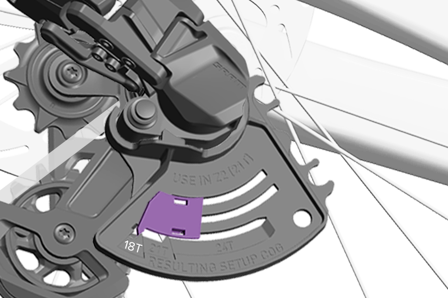
8. Visually inspect the gauge to determine where the indicator slider moved to, this is your Setup Cog position, Gear 1 (24T Cog), Gear 2 (21T Cog), or Gear 3 (18T Cog). If the gauge slider is between two cogs, use the outboard, smaller cog.
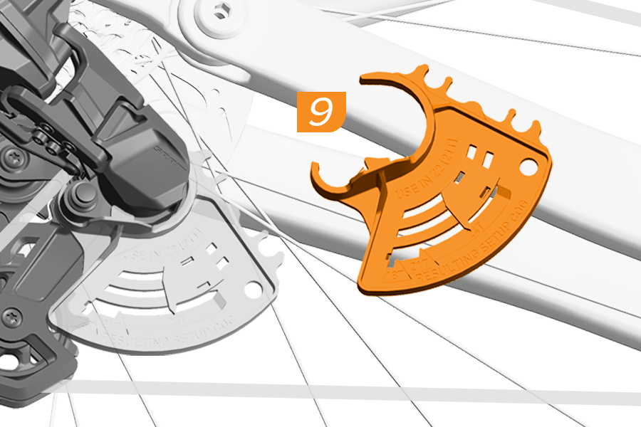
9. Remove the gauge from the derailleur.
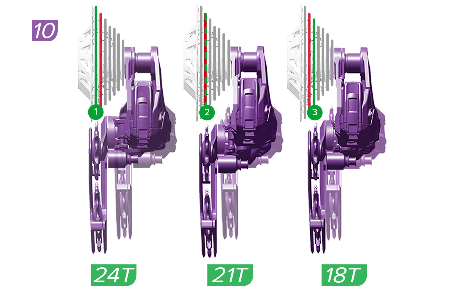
10. If Gear 2 (21T Cog) is identified as the Setup Cog, make sure the cage is pulled back to remove all slack in the chain and tighten the mount bolt to 35 N·m (310 in-lb).
If Gear 1 (24T Cog) or Gear 3 (18T Cog) is your Setup Cog, shift the chain into the cog and gear and proceed to the Tighten section of the manual to complete DH Transmission System Installation.
The XX DH derailleur parallelogram parts are not compatible with other SRAM Transmission derailleurs.
Shift the derailleur to the fully outboard position.
PINCH HAZARD
The p-knuckle is spring-loaded and will return rapidly. Keep fingers clear of pinch points.
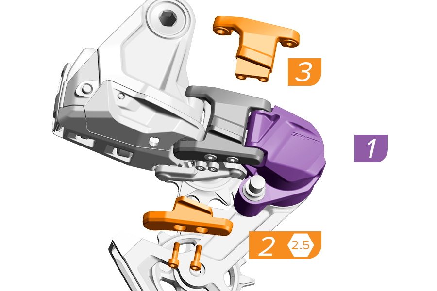
1. Hold the p-knuckle back.
2. Remove the screws on the lower parallelogram.
3. Remove the upper and lower parallelogram.
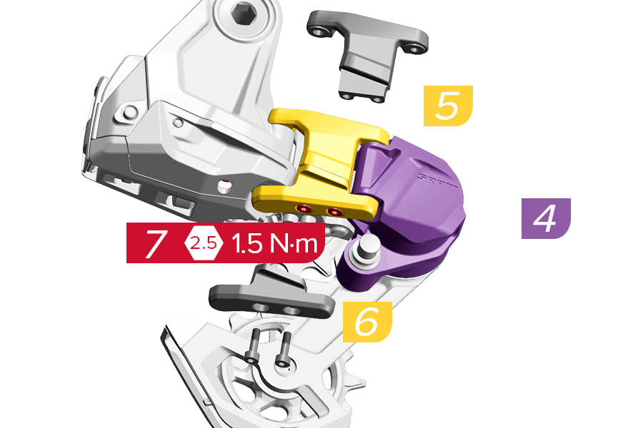
4. Hold the p-knuckle back.
5. Install the upper parallelogram.
6. Install the lower parallelogram.
7. Install and tighten the new, threadlock-prepped screws.
The XX DH Transmission skid plate is compatible with the GX and S1000 skid plate.
The skid plate is not compatible with XXSL, XX, and X0 Eagle Transmission derailleurs.
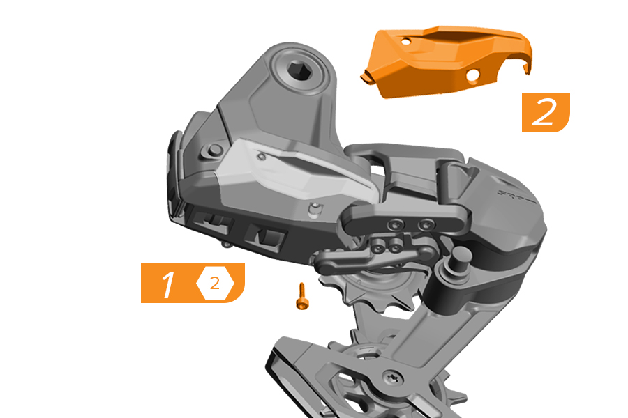
1. Remove the skid plate screw.
2. Pull the skid plate off at the front, near the parallelogram.
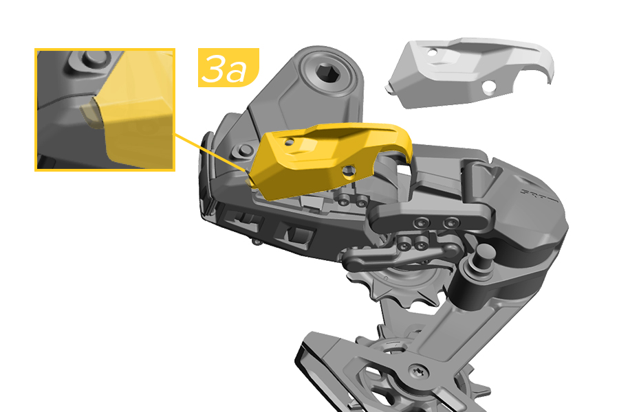
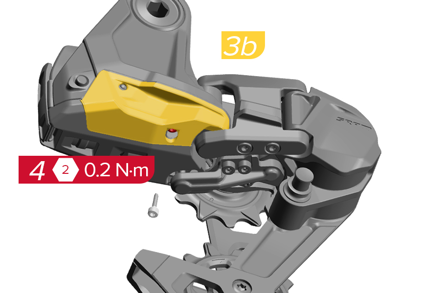
3a. Install the new skid plate with the rear tab inserted first.
3b. Press the front part of the skid plate until it clicks into place near the parallelogram.
4. Install and tighten the screw.
The battery latch is compatible with all Road XPLR AXS derailleurs and GX and S1000 Eagle Transmission derailleurs.
The battery latch is not compatible with XXSL, XX, and X0 Eagle Transmission derailleurs.
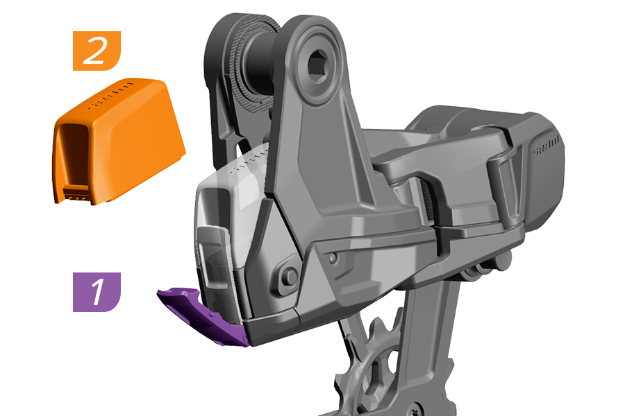
1. Open the battery latch.
2. Remove the SRAM battery.
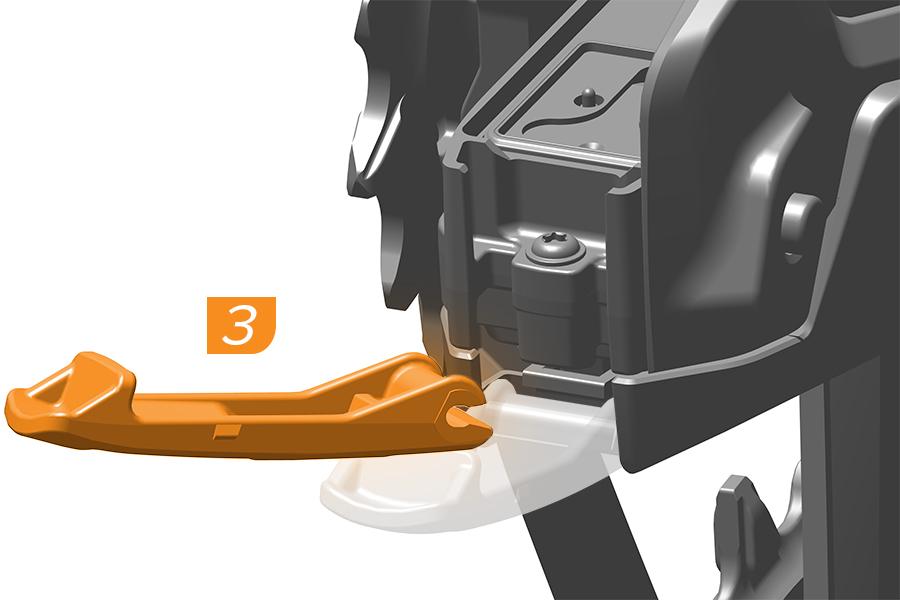
3. Pull the latch away from the derailleur to remove it.
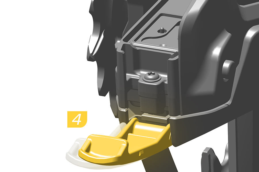
4. Install the new battery latch. When installed correctly, the latch will snap into place.
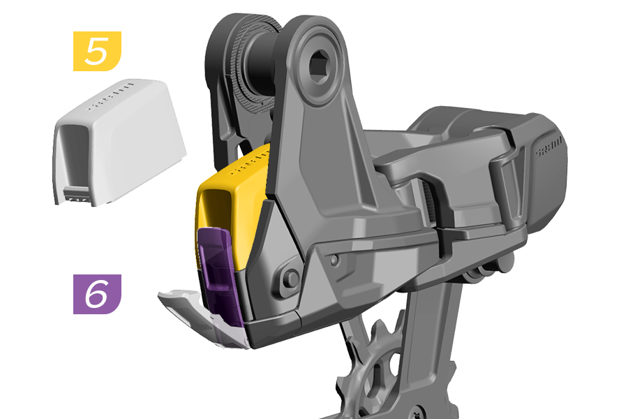
5. Install a SRAM battery into the derailleur.
6. Close the battery latch.
When installed correctly, the latch will snap into place and the LED will flash green once.
The Full Mount service procedure is the same between SRAM Transmission XXSL, XX, X0, GX, S1000, Eagle 90, Eagle 70, and XX DH derailleurs. Consult the Spare Parts Catalog for the compatible mount bolt for your derailleur. A GX Transmission derailleur is pictured for demonstration.
Remove the battery from the derailleur and install the battery block before service.
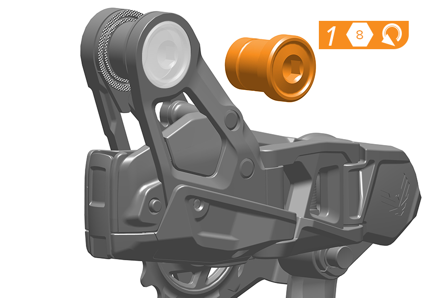

1. Turn the mount bolt counter-clockwise and remove it.
2. Remove the bushing frame insert.
3. Remove the knurled ring.


4-5. Install and rotate the knurled ring clockwise until it touches the knurled ring stop. Make sure the ring stop is between the knurled ring horns.
6. Install the bushing frame insert with the flat side facing outboard.
7. Install the mount bolt.
Proceed to the Prepare, Hang, and Tighten sections for derailleur installation and setup.
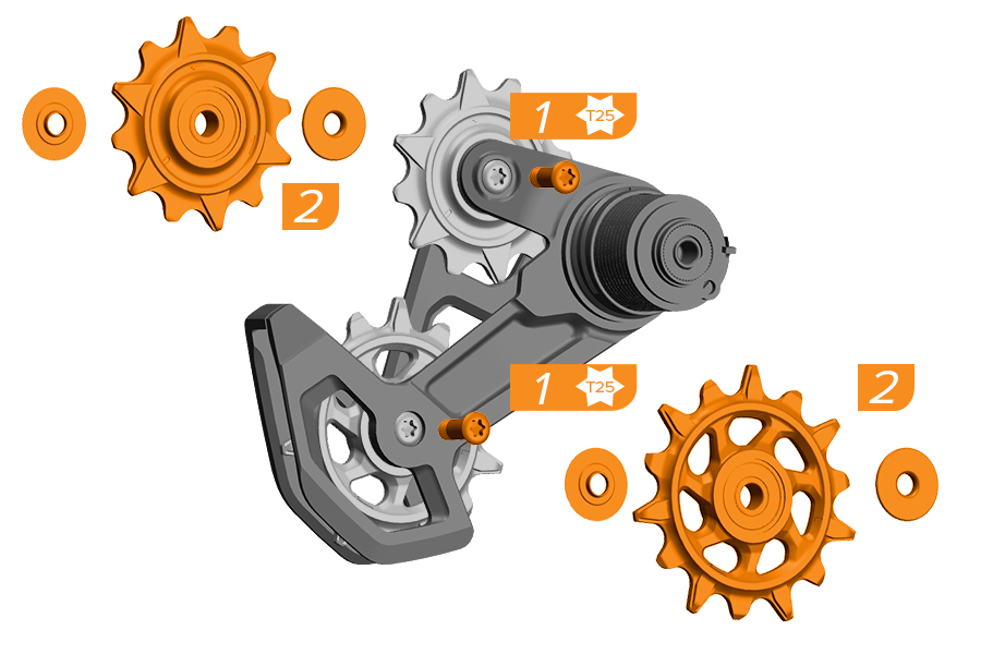
Remove the cage from the derailleur body.
1. Remove the pulley bolts.
2. Remove the pulleys and bushings.
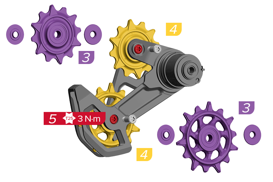
3. Orient a new pulley as shown. Reinstall the bushings with the flat side facing outward.
4. Install the new pulley.
5. Tighten the pulley bolts.
The DH cage pulley wheels are not compatible with Eagle Transmission derailleur cage pulley wheels.
The derailleur cage replacement and damper assembly is not interchangeable between SRAM Transmission XXSL, XX, X0, GX, S1000, Eagle 90 and Eagle 70 derailleurs.
Shift the derailleur into the outboard position before service.
PINCH HAZARD
Hold the cage from the outside to avoid pinching your fingers between the cage and derailleur body when the cage loosens.
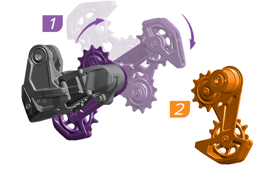
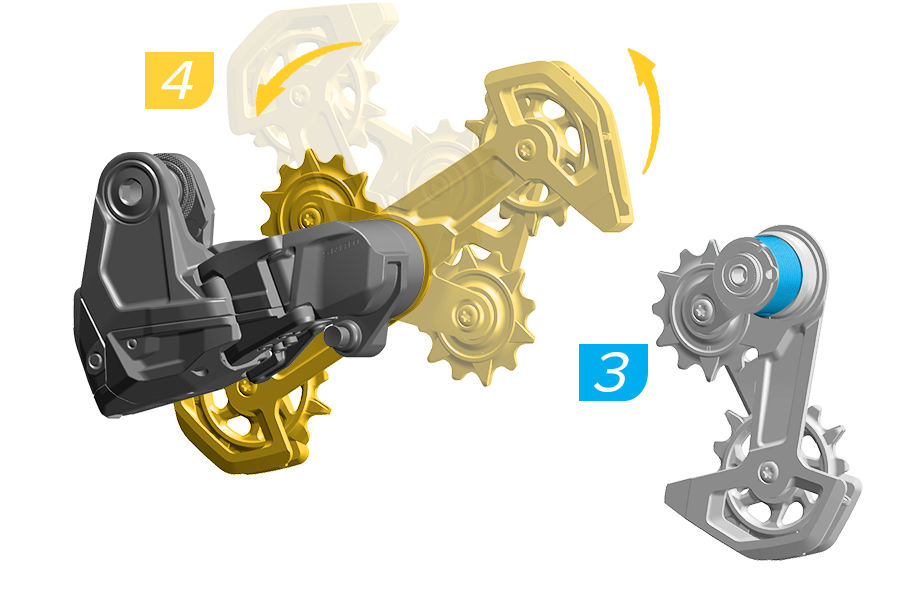
1. Hold the derailleur body and rotate the cage clockwise until it releases from the p-knuckle.
2. Remove the cage.
3. Apply a small amount of grease to the clutch spring before installing the new cage.
4. Install the new cage into the p-knuckle.
It is recommended that you periodically clean your electronic components.
Use a damp cloth to wipe off any dirt and debris. Clean the components with soap and water only. Rinse thoroughly with water and allow the components to dry.
Remove the SRAM batteries and install the battery blocks into the transmission before cleaning.
Do not clean the components with a power washer.
Do not use acidic or grease-dissolving agents. Do not soak or store components in any cleaning product or liquid. Chemical cleaners and solvents can damage plastic components.
Always maintaining a clean and lubricated drivetrain will help extend your system performance and product component service life significantly.
It is recommended that you clean your chain, cassette, and chainring after frequent use, and immediately after riding in muddy, dusty, or other adverse conditions.
Use only biodegradable non-acidic cleaners to clean the cassette, chainring, and chain. Rinse thoroughly with water and wipe dry with a rag or blow dry with pressurized air.
Lubricate the chain with a dedicated chain lubricant. Wipe off excess lube.
CRASH HAZARD
Do not use alkaline or acidic solvents to clean the chain and cassette cogs. Do not soak or store the chain or cassette in any cleaning product. They will become brittle and can break under load, which can cause the rider to crash resulting in serious injury and/or death.
The chain, cassette, and chainring wear together over time as a result of normal use. Parts will last longer with regular cleaning.
To determine if the parts need to be replaced, consult the Transmission Service Matrix. Depending on use case, it may be best to change the parts together to restore optimal drivetrain performance.
After installation and setup, you may remove and reinstall the rear wheel as needed. To remove and install the wheel put the derailleur in Open Mode. Before tightening the rear axle bolt, you must release the Cage Mode button and set the derailleur to Ride Mode.
Failure to put the derailleur in Ride Mode before tightening the thru axle could result in the derailleur being fixed in the wrong position.
Storage conditions: Temperature from -40°C to 70°C ( -40°F to 158°F), humidity from 10% to 85%
Operating conditions: Temperature from -10°C to 40°C (14°F to 104°F), humidity from 0% to 100%
Component Service life: 5 years
Remove the SRAM batteries to preserve battery life during long term storage and when the bicycle is transported. Store the battery at least at 50% charge.
Remove the SRAM batteries and install the battery blocks and battery covers when the bicycle is being transported or not in use for long periods of time. Failure to remove the SRAM batteries could result in battery depletion.
Failure to cover the battery and AXS component terminals could result in damage to the terminals.
It is recommended that you periodically clean your electronic controllers.
Make sure the outside of the controller is clean before removing the button assembly. Use a damp cloth to wipe off any dirt and debris from the control and the underside of the button assembly. Clean the components with soap and water only. Rinse thoroughly with water and allow the components to dry completely before installing the button assembly.
You must periodically clean the controller by removing the button assembly. Riding with dirt and debris in the Pod Controller may result in the controller not working.
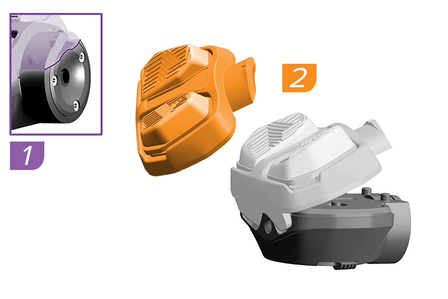
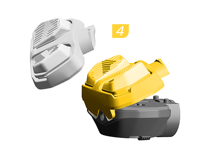
1. Use your fingers to pry off the button assembly by pulling up on the seam above the AXS button.
2. Remove the button interface.
3. Use a damp cloth to wipe off any dirt and debris from the control. Clean the components with soap and water only. Rinse thoroughly with water and allow the components to dry completely.
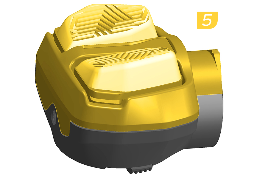
4. Align the button assembly with the controller. Seat the button onto the LED side of the controller.
5. Press the clamp side of the button until you hear and feel it click in place.
♻For recycling and environmental compliance information, please visit www.sram.com/en/company/about/environmental-policy-and-recycling
